Send your good work in the knowledge base is simple. Use the form below
Students, graduate students, young scientists who use the knowledge base in their studies and work will be very grateful to you.
Posted on http://www.allbest.ru/
State Autonomous Professional educational institution Saratov region
Balashov College of Agricultural Mechanization
Topic: "General information about the electrical equipment of the car"
Made by a student of group A-31
Andryushkevich Valentin
Checked by teacher
Denisov Yu.V.
Introduction
Conclusion
Introduction
Vehicle electrical equipment is a complex set of interconnected electrical and electronic systems, instruments and devices that ensure the reliable operation of the engine, transmission and chassis, traffic safety, automation of vehicle work processes and comfortable conditions for the driver and passengers.
Automotive electrical equipment includes the following systems and devices:
Ш Power supply system:
Generator set;
Accumulator battery.
Ш Electric starter engine start (ignition) system.
Accumulator battery;
Electric starter;
Control relay (additional relays and blocking relays);
Electrical devices to facilitate starting the engine.
Spark plug;
Ignition coil;
Breaker-distributor;
Distributor sensor;
Transistor switch;
Additional resistor;
High voltage wires;
Tips
Ш Lighting, light and sound alarm system:
Lighting devices (headlights);
Signal lights (side lights, direction indicators, brake lights, reversing lights);
Ш System of information and control of the technical condition of the car:
Pressure sensors and indicators;
Temperature sensors;
Fuel level sensors in the tank;
Speedometer;
Tachometer;
Ш Electric drives:
Ш Switching, protective devices and electrical wiring.
Switches;
Switches;
Relays for various purposes;
Contactors;
Fuses and fuse blocks;
Connection panels;
Removable connections.
The development of electrical equipment of cars is closely related to wide application electronics and microprocessors that provide automation and optimization of work processes, greater traffic safety, reduced toxicity of exhaust gases and improved working conditions for drivers.
The number and power of electricity consumers in cars is constantly increasing. Accordingly, the power of electrical energy sources increases.
The old electrical equipment is being replaced by new, more complex in design and circuit solutions, electrical and electronic products and systems. electrical equipment generator battery starter
The operational reliability and performance of the vehicle largely depends on the technical condition of the electrical equipment.
1. General battery device
The operation of the battery is based on the principle of the occurrence of a potential difference (voltage) between two plates immersed in an electrolyte solution. For the first time, an element operating on this principle was created in 1836-1838. One plate in it was copper, the second was zinc, which dissolved very quickly.
Over the past decades, the element has been modernized, devices that generate electricity have become much more compact and productive, and besides, they have “learned” to repeatedly restore their resource. However, the general principle of the battery remains unchanged.
Battery device
The creation of a lead-acid battery belongs to the French physicist Gaston Plant in 1859. The area of the first battery was 10 square meters. m. A modern battery is a hundreds of times smaller copy of Plant's battery.
The only visible element of the car battery is the case, which ensures the integrity and generality of the design. Very high and stringent requirements are imposed on the battery case. It must be immune to aggressive chemicals, endure significant temperature fluctuations and have high vibration resistance. In the vast majority of cases, the case is made of modern synthetic material - polypropylene. The case consists of two parts: from the main deep container, and the lid covering it.
In each of the individual cells, a package assembled together is installed, consisting of many individual plates, the polarity of which alternates. The plates made of lead have a lattice structure of rectangular honeycombs. This design allows you to put on them the main working reagent - the active mass.
Since it is applied by spreading, the battery is called that - with spread-type plates.
There are two more types of batteries - in some, plates of an increased area are installed, and in the second - from a shell mesh. However, in the manufacture of car batteries, only smeared plates are used.
Since each of the alternating plates is an electrode with opposite polarity, it is necessary to prevent the possibility of short circuiting them. For this purpose, a separator made of porous plastic is inserted between each pair of plates, which does not prevent the circulation of the electrolyte inside the cell. Due to the fact that each plate carrying a positive charge is placed between two "negative" plates, there is always one more negative plate in the cell.
The entire assembled package is fixed from possible displacements and deformations with a special bandage. The positive and negative current outputs of the plates are combined in pairs and, with the help of current collectors, concentrate their energy on the output borons of the battery. They are connected to the current-collecting terminals of the car.
Battery marking
Each battery must have its own marking that displays all the necessary information about it that the buyer should know. Basically, this is the battery capacity, voltage, its type and purpose.
The marking of the battery for each country of manufacture is different and differs significantly.
Example, battery markings and decoding of symbols:
In this example:
6- denotes the number of series-connected small batteries that make up the main battery. (sometimes 3, 6 or more batteries). By their number, you can determine the voltage that the battery produces. Each battery produces a voltage of 2 V (based on this, if there are 3 batteries in a bank, then we get 6 V, if there are six cans, then 12, and if 12 cans, then 24 V)
ST- indicates that the battery is a starter.
75 - shows the battery capacity (in Ah)
Battery marking also involves the use of special letters and numbers at the end of the marking itself. In this example, A1.
It gives us information about the way the battery is produced and the materials from which it was made.
"A" - means that the battery has a common cover. (If we see the letter "Z", then this is a battery that is filled and fully charged. If there is no letter "Z", then the battery is dry-charged).
And yet, the marking of the battery suggests indicating the following information:
Trademark from the manufacturer's factory, nominal capacity in Ah, starting current (in A) at -18 degrees Celsius (otherwise it is also called cold scroll current). The voltage that the battery produces in volts, the date of manufacture, the weight of the battery, and polarity signs are required, since they can be placed differently on different batteries.
Additional warning signs such as no smoking, caustic. Filled electrolyte level according to the lower or upper mark.
All battery markings comply with the requirements of the standards adopted in a particular country and are applied to the battery in the area of \u200b\u200bthe cover or side using a special stencil.
However, no matter what the marking of the battery is, it must be clear and understandable, resistant to external influences and retain these properties throughout the entire period of its operation.
2. General arrangement and principle of operation of the generator
Generator - a device that converts mechanical energy received from the engine into electrical energy. Together with the voltage regulator, it is called a generator set. Alternators are installed on modern cars. They best meet the requirements.
Requirements for the generator:
Ш output parameters of the generator must be such that in any modes of vehicle movement there is no progressive discharge of the battery;
Ш voltage in the on-board network of the car, fed by the generator, must be stable in a wide range of changes in speed and loads.
The last requirement is due to the fact that the battery is very sensitive to the degree of voltage stability. Too low voltage leads to undercharging of the battery and, as a result, difficulties in starting the engine, too high voltage leads to overcharging of the battery and its accelerated failure.
The main parts of the generator:
1. Pulley- used to transmit mechanical energy from the engine to the generator shaft by means of a belt;
2. generator housing- consists of two covers: front and rear, designed to mount the stator, install the generator on the engine and accommodate the rotor bearings. The back cover contains a rectifier, a brush assembly, a voltage regulator (if it is built-in) and external leads for connecting to an electrical equipment system;
3. Rotor- a steel shaft with two beak-shaped steel bushings located on it. Between them there is an excitation winding, the conclusions of which are connected to slip rings. The generators are predominantly equipped with cylindrical copper slip rings;
4. stator- a package made of steel sheets, having the shape of a pipe. In its grooves is located three-phase winding, in which the generator power is generated;
5. Assembly with rectifier diodes- combines six powerful diodes, pressed three into the positive and negative heat sinks;
6. Voltage regulator- a device that maintains the voltage of the vehicle's on-board network within the specified limits when the electrical load, generator rotor speed and ambient temperature change;
7. brush knot- Removable plastic construction. It has spring-loaded brushes in contact with the rotor rings;
8. Protective cover for diode module
The principle of operation of the generator
The principle of operation of an alternator is based on the conversion of mechanical energy into electrical energy due to the rotation of a wire coil in a created magnetic field. This device consists of a fixed magnet and a wire frame. Each of its ends is connected to each other by means of a slip ring, which slides over an electrically conductive carbon brush. Due to such a scheme, an electrically induced current begins to pass to the inner slip ring at the moment when the half of the frame connecting to it passes the north pole of the magnet and, conversely, to the outer ring at the moment when the other part passes the north pole.
The main part of the work is in the rotation of the c/o. The new cars have a hybrid type, which also serves as a starter. The principle of operation is to turn on the ignition, in which the current moves through the contact rings and is directed to the alkaline node, and then switches to rewinding the excitation. As a result of this action, a magnetic field will be formed. Together with the crankshaft, the rotor begins its work, which creates waves penetrating the stator winding.
AC current begins to appear at the rewind output. When the generator is operating in the self-excitation mode, the rotational speed increases to a certain value, then it starts to change in the rectifier unit AC voltage for permanent. Ultimately, the device will provide consumers with the necessary electricity, and the battery will provide current.
3. General arrangement and principle of operation of the starter
The starter is used to start the engine. To do this, it provides the primary rotation of the crankshaft with the required frequency. The starter is an integral part of the electrical equipment of any modern car. Structurally, it is a four-pole electric motor direct current powered by a battery. Its power varies, depending on the specific modification of the car, however, a 3 kW starter is enough to start most gasoline engines.
The starter device includes the following main components:
Sh Case - a steel detail of a cylindrical form. It contains windings and cores.
Ш Anchor - made in the form of an axis of alloy steel. At the anchor, the core and collector plates are pressed in.
Ш Retractor relay - designed to supply power to the starter motor from the ignition switch. At the same time, it performs another function - it pushes the overrunning clutch. The relay has in its design power contracts and a movable jumper.
Ш Overrunning clutch (bendigs) and drive gear - a roller mechanism that transmits torque to the flywheel crown through a special engagement gear. After starting the motor, it disconnects the drive gear and the flywheel crown, thereby ensuring the safety of the starter.
Ш Brush holders and brushes - designed to supply operating voltage to the collector plates of the armature. Increase the power of the electric motor, during the implementation of the main operating cycle of the starter.
According to the type of its design, the starter can be:
with gearbox
without gearbox.
On engines with a diesel power system, as well as on engines of increased power, a starter with a gearbox is installed. The planetary gearbox, consisting of several gears, is mounted in the starter housing. It amplifies the passing voltage several times, thereby increasing the torque. Gear starter has the following advantages:
It is more efficient, has a high efficiency;
consumes much less current during a cold start of the engine;
· the gear starter has more compact overall dimensions;
Maintains high efficiency and excellent performance characteristics when the starting current of the battery drops.
The principle of operation without geared starters is in direct contact with a rotating gear.
Among the advantages of such a device are:
1. simplicity of the device and higher maintainability;
2. faster start of the motor, due to instant connection with the flywheel crown after current is applied;
The principle of the starter
After closing the contacts in the ignition switch, the current is sent through the starter relay to the solenoid winding of the traction relay. The armature of the retractor relay, moving inside the housing, pushes the bendix out of the housing and engages its gear with the flywheel crown. When the armature of the solenoid relay reaches its end point, the contacts close and current flows to the holding coil of the relay and the coil of the starter motor. Rotation of the starter shaft starts the engine of the machine.
After the speed of rotation of the flywheel exceeds the speed of rotation of the starter shaft, the bendix disengages from the crown and is set to its original position with the help of a return spring. When the key in the ignition switch with engine start is returned to the first position, the power supply to the starter is cut off.
4. Contact-transistor ignition system. Modern ignition system
Used on cars various systems electric spark ignition: contact, contact-transistor, non-contact-transistor, electronic-digital, microprocessor.
1. Transistor ignition systems
Transistor ignition systems are usually divided into two groups: contact-transistor and non-contact-transistor.
Contact-transistor ignition system- was a transitional stage from contact to contactless electronic systems. It eliminates the disadvantage of the contact system - burning and wear of the breaker contacts that switch the circuit with inductance and significant current strength. In a contact-transistor system, the primary circuit of the excitation winding is switched by a transistor controlled by the breaker contacts.
With the use of a contact-transistor system, a new unit appeared on the car - an electronic switch, which combines a power switching transistor and elements of its control and protection circuit.
Transistors are called semiconductor devices designed to amplify, generate and convert electrical oscillations.
A transistor has three terminals: collector, emitter and base.
Collector current flows along the collector-emitter path. A weak control current flows along the other base-emitter path. And with the help of this base current, the collector current is controlled.
Moreover, the collector current is always greater than the base current by a certain number of times. This value is called the current gain. At various types transistors, this value ranges from units to hundreds of times.
If you increase the base current, then the emitter-base junction opens up more, and more electrons can slip between the emitter and collector. And since the collector current is initially greater than the base current, this change will be very noticeable. Thus, there will be an amplification of a weak signal received at the base.
When the contacts of the breaker are closed, the base current of the transistor begins to flow through them, which opens and turns on primary winding ignition coils to the power supply.
When the breaker contacts are opened, the transistor closes, the current in the primary circuit is abruptly interrupted and a surge appears on the candles high voltage, as in the contact system.
The characteristics of the contact-transistor system are similar to the contact, except that the reduction of the secondary voltage by low frequencies, the cam does not rotate.
The service life of the breaker contacts in the contact-transistor system is longer than in the contact one.
Operation of the contact-transistor ignition system
When the ignition switch (8) is on, after closing the contacts 4 of the breaker, the switch transistor (5) opens, and current will flow through the primary winding (7) of the ignition coil. At the moment of opening the contacts of the breaker, the switch transistor is closed.
The current in the primary circuit decreases sharply, and a high voltage current is created in the secondary winding (6) of the ignition coil. It is fed to the rotor(2) of the ignition distributor(3), which distributes the high voltage current to the spark plugs(1) according to the engine's firing order.
contactless-tresistor ignition system-- this is a system with a purely electronic device for controlling the primary current of the ignition coil and with a non-contact electric pulse sensor of the ignition moment, which, like the contact pair in the classic breaker-distributor, is located on the movable platform of the drive roller of the mechanical high-voltage distributor. The position of the movable platform relative to the axis of the drive roller (angle of rotation) can be controlled by ignition advance devices (centrifugal and vacuum). The movable platform and the proximity sensor activator installed on it are an electromechanical ignition timing control device. Such a control device, together with a high-voltage distributor, form a so-called sensor-distributor.
The electronic device for controlling the primary current in a non-contact transistor power system is structurally made in the form of a separate unit, which is called a switch. At the output, the switch is connected to the ignition coil, and at the input it is controlled by an electric pulse input sensor on the distributor.
Thus, a non-contact transistor ignition system is a combination of an electronic switch, a distribution sensor, an ignition coil and an output executive periphery: high-voltage wires and spark plugs.
Non-contact transistor ignition systems began to be installed on passenger cars in the late 60s and have been constantly improved since then.
2. Electronic and microprocessor ignition systems
The contact and non-contact-transistor ignition systems were replaced by systems with electronic computing control devices and without a high-voltage energy distributor for candles in the output stage. Such systems are divided into: electronic computing (electronic) and microprocessor.
Electronic and microprocessor ignition systems differ from previous systems:
1. Their control devices are electronic computing units of a discrete principle of operation, made using microelectronic technology and designed to automatic control moment of ignition. These devices are called controllers.
2. The use of microelectronic technology, in addition to obtaining advantages in reliability, can greatly expand the functions of electronic control.
Electronic and microprocessor ignition systems differ from each other in the ways in which the main ignition signal is generated.
In the electronic system, the main ignition signal is generated using the time-pulse method of converting information from input sensors.
It is when controlled process is set by the time of its flow, with the subsequent conversion of time into the duration of the electrical impulse. Thus, in an electronic system, the controller contains an electronic chronometer and is controlled by analog signals.
In the microprocessor ignition system, a number-pulse conversion is used, in which the process parameter is set not by the flow time, but directly by the number of electrical impulses.
The functions of the electronic calculator here are performed by a number-pulse microprocessor, which operates on electrical impulses stabilized in amplitude and duration. Therefore, between the microprocessor and the input sensors in the ECU, number-pulse converters of analog signals to digital ones are installed.
Unlike electronic, the microprocessor ignition system works according to a control program pre-set for a given engine. Therefore, the calculator of the microprocessor ignition system has electronic memory (permanent and operational).
Electronic control units for electronic and microprocessor ignition systems have design differences:
In the electronic system, the control unit is an independent structural unit and is called the controller.
Signals from the input sensors of the ignition system are fed to the controller inputs, and at the output, the controller works on the electronic switch of the output stage. All electronic circuits controllers are low-level (potential), which allows them to be included in other on-board electronic control units.
In the microprocessor ignition system, all control functions are integrated into the central on-board computer of the vehicle and there may be no personal control unit for the ignition system. The functions of the input sensors are performed by universal sensors of the integrated automatic engine control system. The main ignition signal is fed to the electronic switch of the output stage directly from the central on-board computer.
5. Headlights and headlights
A set of lighting devices and signaling devices located outside and inside the car form a lighting system. It performs the following functions:
Illumination of the roadway, curbs and objects located on them in conditions of limited visibility;
providing information to other road users about the presence on the road vehicle, its size, nature of movement, maneuvers performed, as well as belonging;
· lighting of the car interior, as well as other parts of it (luggage compartment, engine compartment, etc.) at night.
The vehicle lighting system includes the following main structural elements: headlights, front fog lights, rear lights, rear fog light, license plate light, interior lighting devices and control equipment.
Headlight (headlight, block headlight) - illuminates the road in front of the car, and also provides information to other road users in front of the vehicle. Headlights are installed in pairs symmetrically on the right and left sides of the car
The headlight is made, as a rule, in a single housing, which combines the following lighting devices: low beam, high beam, side light, direction indicator and daytime running lights.
low light- headlights are used to illuminate the road when there are other road users in front. The dipped beam is asymmetric, with right-hand traffic, the right side of the road and the shoulder are better illuminated. distant light- used when there are no other road users ahead. It is a symmetrical light beam of high intensity. Dimensional fire- used to indicate the dimensions of a vehicle. The marker light is also installed in the rear light. Turn indicator- can be installed both in the headlight unit and outside it in the front of the car. The direction indicator is used to inform other road users of the intention to make a maneuver (turn, U-turn, lane change). The direction indicator is also installed in the rear light.
In addition, a turn signal repeater is provided on the side of the car. All direction indicators must work synchronously. The turn signal uses an amber light source that works in flashing mode. The frequency of the pointer should be 1-2 flashes per second. The direction indicator can have two modes of operation: constant (until it is turned off), one-time (three to five flashes when pressed). The direction indicator is controlled by the corresponding switch. The switch is designed to automatically turn off the signal when the steering wheel is returned to the neutral position. The direction indicators are also used as an emergency stop signal.
Some countries provide for the use of daytime running lights, which are intended to increase the visibility of the vehicle during the daytime. Daytime running lights are automatically or manually controlled dipped beam headlights with full or reduced intensity. In some cases low-intensity high beam headlights may be used.
headlight device
Despite the differences in shape, design, color, materials can be distinguished general device headlights: housing, light source, reflector and diffuser.
Housing - serves as the basis for the placement and fastening of the remaining elements of the headlight. It is made of plastic. Various lamps are used as light sources: incandescent - tungsten, halogen, gas-discharge - xenon. LED light sources are gaining more and more popularity among automakers.
Tungsten lamps- the cheapest in price and have low light intensity. Therefore, these lamps are used as a light source for parking lights, direction indicators, brake lights, reversing lights, interior lighting devices. Halogen lamps- are the most common source of low and high beam headlights. Tosenon lamps- Can be used for both low beam and high beam. LED- are used mainly for the implementation of signaling functions: parking lights, brake light, turn signal, daytime running lights. Less commonly, LEDs can be seen as a head light source.
The reflector in the design of the headlight is responsible for the formation of a beam of light. The simplest reflector has a parabolic shape. Modern reflectors have a more complex shape. The reflector is made of plastic. To create a mirror surface, a thin film of aluminum is applied and varnished.
Diffuser - transmits the light flux and, depending on the design, refracts it. Another function of the diffuser is to protect the headlight from external influences. The diffuser is made of transparent plastic, less often glass.
The light source is a lamp or a set of super-bright LEDs that provide the necessary luminous flux. Conventional incandescent lamps give a flow of up to 550 lm, double-filament halogen lamps - up to 1000 lm (dipped beam) and up to 1650 lm (high beam), single-filament high beam lamps - up to 2100 lm, and gas-discharge xenon - up to 3200 lm.
Conclusion
The reliability of the operation of vehicles is influenced by the state of electrical equipment, the operation of the battery and charging system, and the correct adjustment of light and signal devices. Trouble-free operation of electrical equipment devices is achieved by diagnostics, a set of adjusting and preventive actions during maintenance car. The operability of the entire electrical system depends on the good condition of the battery, generator, relay-regulator of the ignition system, starter of instrumentation and lighting and signaling devices.
Hosted on Allbest.ru
...Similar Documents
General information about the modern ignition system of carburetor engines. Breaker-distributor, coil, candles and ignition lock: device, purpose and principle of operation. Scheme of the battery ignition system. Installing the ignition in the engine.
abstract, added 07/14/2010
Characteristics of the control object, description of the structure and operation of the ACS, drawing up its functional diagram. Learning how the system works automatic regulation air temperature. Determination of transfer functions of the system and stability margins.
term paper, added 09/10/2010
Construction of a logical circuit of a combination node and a circuit diagram of a discrete control device. Study of the principle of operation of the device, its purpose and structure. Analysis of the principle of rigid logic on integrated circuits.
practical work, added 12/27/2012
General information about asynchronous machines. General information about operating modes induction motor. Analytical and graphical definition of operation modes of an asynchronous reconstruction machine.
abstract, added 06/20/2006
Consideration of the device, the principle of operation, specifications and advantages of using OM-1 and TOM-2A milk cleaners-coolers, OPF-1 pasteurization unit, tanks with automatic washing and control, ice tank and MC\|IC (P) system.
laboratory work, added 05/01/2010
Consideration technological scheme reception, averaging, shipment of iron ore raw materials. Stages of the process of agglomeration of concentrates and flue dust: preparation and sintering of the sinter charge. Study of the device and principle of operation of the sintering machine.
term paper, added 06/20/2010
Characteristics of the technology of the GKL packaging line. Description of the structure, device and principle of operation of the packaging management system. Power supply and safety features. Calculation of capital costs for a microprocessor control system.
thesis, added 06/23/2010
Get to know your device microwave oven. Consideration of the nature of microwave electromagnetic radiation. Invented by Percy Spencer. Study of the influence of microwaves on the human body; compliance of this device with Federal Sanitary Regulations.
abstract, added 11/29/2014
Printed circuit board of a key transistor cell. Search for elements in the ORCAD package database. Missing library items. principled circuit diagram in the DRAFT.EXE schematic editor. Creating a file of errors and links. PCB size.
term paper, added 04/28/2009
The history of the development of the sewing machine, the reliability of machines manufactured by the Singer company. General information about the mechanisms of the sewing machine. Shuttle types. The device of the sewing machine and the principles of its operation. Types of sewing machines and their purpose.
Vehicle electrical equipment
Vehicle electrical equipment- a set of devices that generate, transmit and consume electricity in a car.
Vehicle electrical equipment is a complex set of interconnected electrical and electronic systems, instruments and devices that ensure the reliable operation of the engine, transmission and chassis, traffic safety, automation of vehicle work processes and comfortable conditions for the driver and passengers.
On-board power supply parameters
Almost always used to power on-board electrical receivers constant pressure. Early cars used 6 volts, now 12 volts prevails on cars and light trucks, and 24 volts on heavy trucks and buses.
The wiring is usually single-wire - the "mass" is used as the second wire - the metal body and frame of the car. This simplifies and reduces the cost of wiring, but reduces its reliability in relation to short circuits.
Power supplies
On the vast majority of modern cars, the power source is a synchronous three-phase alternator driven by the main engine; three-phase alternating current from the generator goes to a three-phase rectifier, usually arranged in the generator housing. To power consumers when the engine is not running, in particular, for the initial start of the engine, a battery is used, recharged from the generator when the engine is running.
Older cars used a DC generator; his hallmark was that it began to produce sufficient voltage only at high engine speeds - at low speeds, consumers were powered only by the battery, which often led to its discharge.
In some cases, an additional generator driven by a separate small engine is installed on cars, which makes it possible to supply consumers with electricity regardless of the operation of the main engine.
Auxiliary devices
These include: switches and switches, relays, fuses, connector blocks.
Electricity consumers
Light fixtures
Main article: Vehicle lighting
Automobile lighting devices are divided into external and internal.
- The external ones include headlights (with low and high beams), side lights, direction indicators (combined with alarms), brake lights, reversing lights, license plate lights, fog lights, and in some cases decorative lamps.
- Interior lighting includes interior lamps, engine compartment lamp, trunk lamp, glove box lamp, dashboard backlight lamps, etc.
Other consumers
- Motors for fans, wiper drives, power windows, etc.
- Seat servos
- Radio receiver (radio)
- Sound signal
Some species household appliances can also be powered from the car's mains (connection is via the cigarette lighter socket). On some machines with powerful generators, an inverter with a 220 volt output can be installed to power conventional household appliances.
Links
Wikimedia Foundation. 2010 .
See what "Electrical equipment of a car" is in other dictionaries:
car electrical equipment- — [Ya.N. Luginsky, M.S. Fezi Zhilinskaya, Yu.S. Kabirov. English Russian Dictionary of Electrical Engineering and Power Industry, Moscow, 1999] Electrical engineering topics, basic concepts EN car electrical equipment ...
electrical equipment- A set of electrical products and (or) electrical devices designed to perform a given job. Electrical equipment, depending on the installation object, has the appropriate name, for example, electrical equipment ... Technical Translator's Handbook
I; cf. Aggregate electrical appliances, devices, machines, etc., used where l., necessary for the production of any l. works. E. shop. Warehouse of electrical equipment. // A complex of electrical devices on what l. E. ships. E. car. E.… … encyclopedic Dictionary
electrical equipment- I; cf. a) A set of electrical appliances, apparatus, machines, etc., used where l., necessary for the production of some l. works. Electrical equipment/workshop. Warehouse of electrical equipment. b) resp. A complex of electrical devices on what l. ... ... Dictionary of many expressions
GOST 28751-90: Electrical equipment of vehicles. Electromagnetic compatibility. Conducted interference in power circuits. Requirements and test methods- Terminology GOST 28751 90: Electrical equipment of vehicles. Electromagnetic compatibility. Conducted interference in power circuits. Requirements and test methods original document: On-board network A set of vehicle power wires, including ... ... Dictionary-reference book of terms of normative and technical documentation
GAZ A, brand of the first cars Gorky Automobile Plant (see GAZ (company)), produced in 1932 37. Under an agreement dated May 31, 1929 with Ford (see FORD MOTOR), the USSR received technical assistance for nine years during the construction and start-up ... ... encyclopedic Dictionary
Daewoo Lanos ... Wikipedia
This article is proposed for deletion. An explanation of the reasons and the corresponding discussion can be found on the Wikipedia page: To be deleted / November 22, 2012. Until the discussion process is completed, the article can be ... Wikipedia
Vehicle electrical network. Combines sources and consumers of electricity. Contents 1 Car on-board network 1.1 Motorcycle on-board network ... Wikipedia
12V car battery(may be referred to as a battery for short) is a type of electric battery used in motor vehicles or motor vehicles. Battery energy is used in the first place ... Wikipedia
To category:
1Domestic cars
The general scheme of the electrical equipment of the car
Control devices, a sound signal, electric motors, a radio receiver and other devices that do not have individual (built-in) protection are protected by fuses.
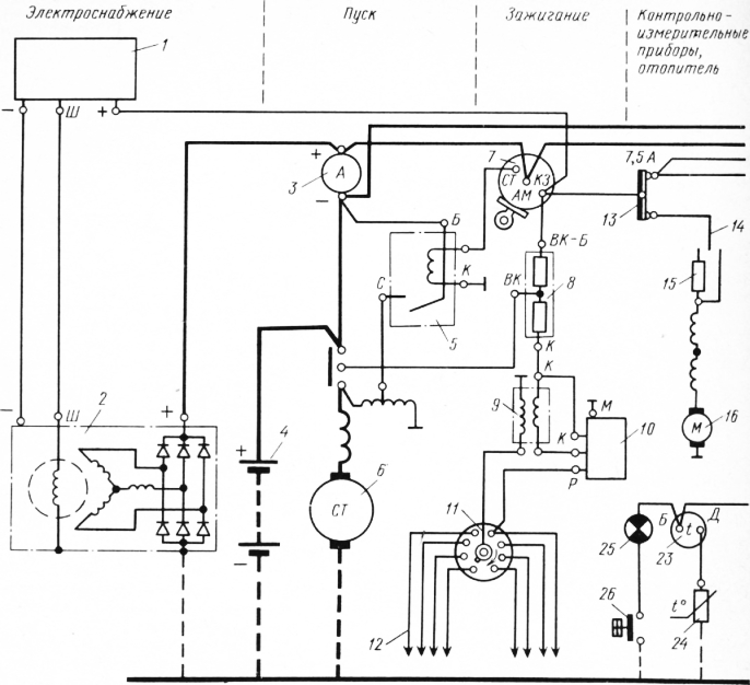
Rice. one. circuit diagram electrical equipment of the ZIL-130 car: 1 - relay-regulator, 2 - generator, 3 - ammeter, 4 - battery, 5 - starter relay, 6 - ST130-A1 starter, 7 - ignition lock, 8 - additional resistance, 9 - coil ignition switch, 10 - transistor switch, 11 - distributor, 12 - spark plug, 13 - bimetallic fuse block, 14 - heater motor switch, 15 - heater motor resistance, 16 - heater motor, 17 - relay-interrupter of direction indicators, 18 - lamp control lamp, 19 - indicator lamp for emergency water overheating, 20 - temperature sensor, 21 - fuel level indicator, 22 - fuel level indicator sensor, 23 - water temperature indicator, 24 - water temperature indicator sensor, 25 - emergency drop indicator lamp oil pressure, 26 - pressure gauge contact, 27 - turn signal switch, 28 - brake light switch, 29, 30 - rear lights, 31 - sidelight, 32 - headlight, 33 - switch light switch, 34 - engine compartment lamp, 35 - ceiling light switch, 36 - ceiling light, 37 - foot light switch, 38 - high beam control lamp socket, 39 - instrument lighting lamp holders, 40 - bimetallic fuse, 41 - plug socket, 42 - sound signal, 43 - horn button (included in the steering column kit), 44 - plug socket, 45 - turn signal repeater lamp
The ignition and start circuits are not protected against short circuits so as not to reduce their reliability in operation.
Thermal fuses are divided into multiple and single action fuses. When an overload or short circuit occurs in the circuit, the contact of the multiple blow fuse pulsates, turning the circuit on and off. The contacts of the single-acting fuse open in these cases. Turn on the fuse (close the contacts) by pressing the button.
Fusible fuse links are replaced after the elimination of the causes that caused short circuit. When replacing a fusible insert, only wire of the appropriate section is used. For example, with a maximum fuse current of 10 A, the tinned copper wire of the fusible link should have a diameter of 0.26 mm (for 15 A, respectively, 0.37 mm). It is strictly forbidden to use thicker wire (“bugs”) or factory fuses designed for a higher rated current.
In order to prevent electrical wiring malfunctions, it is recommended:
- periodically clean the wires, screw and plug terminals from dirt and moisture;
- pay special attention to the condition of screw and plug connections, preventing their corrosion, oxidation and loosening of connections. To prevent oxidation of the contact surfaces of the joints, lithol lubricant, etc. is used;
- regularly check the voltage drop in the circuit sections and contact connections of the main consumers of electricity.
Most of the malfunctions of the electrical equipment of cars occur as a result of untimely and poor-quality maintenance.
The main malfunctions in the on-board network are:
- break in the chain of sources and consumers of electrical energy;
- excessive voltage drop in the circuit of sources and consumers of electrical energy;
- short circuit of wires and insulated parts and assemblies of devices to the body (ground) of the car.
It is advisable to start the search for the cause of the malfunction by checking by hand the reliability of fastening the wire lugs on the terminals of electrical devices, because a significant part of the malfunctions in the electrical system occurs when these lugs are loosened. At the same time, the resistance in the circuit increases, the temperature of the terminals increases, and when the car moves, due to vibration, the contact in the circuit is even broken.
An open in the circuit of sources and consumers of electrical energy occurs due to the melting of a fuse, opening of contacts in a thermal bimetallic fuse, rupture of wires, loose fastening of wire tips on the terminals, contact failure in the plug-in connection of wires, contact failure in switches and switches, open circuit in consumers (burnout filaments in the lamp, burnout of an additional resistor or motor winding, etc.).
Due to the widespread use of electronics in cars, fuses are widely used, which are installed in separate pads or blocks. When troubleshooting a circuit, it is convenient to use diagrams and tables with a list of consumers protected by numbered fuses (tables are given in the car's factory operating instructions). In order to make sure that the fuse is working, it is necessary to turn on the consumers protected by this fuse in turn. If at least one consumer works, the fuse is good.
If a fuse insert has melted, before replacing it with a new one, it is necessary to eliminate the malfunction that caused the fuse insert to melt. If there is no spare insert, you can solder the insert to the contacts copper wire with a diameter of 0.18 mm for a current of 6 A, 0.23 mm - for 8 A; 0.26 mm - at 10 A, 0.34 mm - at 16 A, 0.36 mm - at 20 A.
Before installing a new insert, it is necessary to bend the holder terminals, which will ensure reliable contact between the insert and the holder. Using the example of a simple circuit of the electrical equipment of a GAZ-bZA car, we will consider the search for wire breaks and other malfunctions of the on-board network (Fig. 2). For example, headlights do not light up.
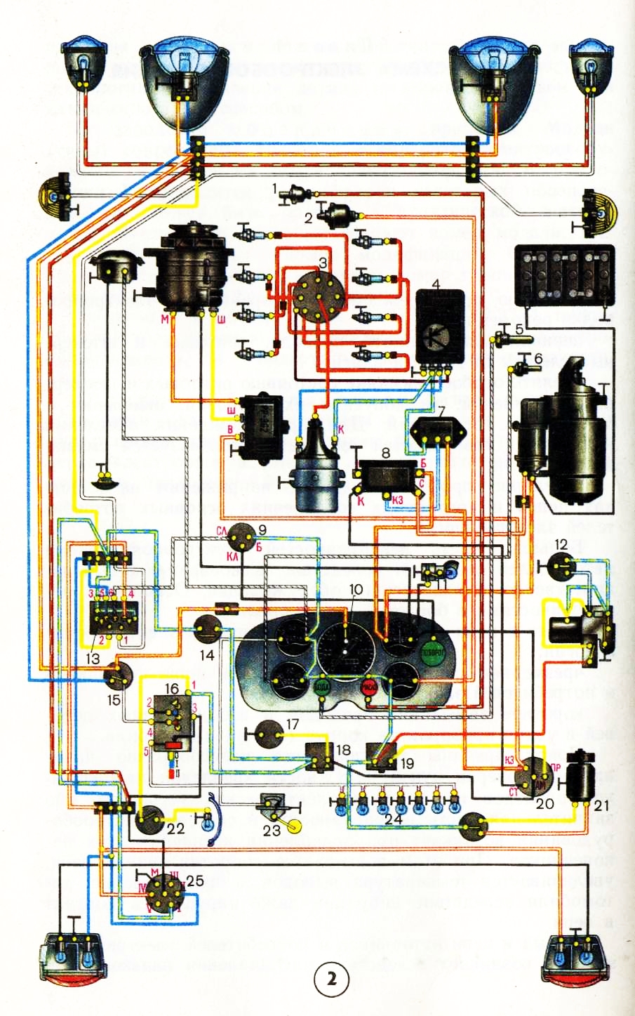
Rice. 2. Scheme of the electrical equipment of the GAZ-63A car: 1 - sensor of the emergency oil pressure warning lamp; 2- gauge indicator of the oil pressure gauge in the lubrication system; 3- breaker-distributor; 4 - transistor switch; 5 - engine overheat indicator sensor; 6 - engine coolant temperature indicator sensor; 7 - additional resistors; 8- starter enable relay; 9- interrupter of direction indicators; 10 - control lamp for switching on the high beam of headlights; 11 - engine compartment lamp; 12 - wiper motor switch; 13-switch of direction indicators; 14 - stoplight switch; 15 - foot light switch; 16 - central light switch; 17-pin socket for portable lamp; 18, 19 - thermobimetallic fuses; 20-ignition switch; 21 - heater motor; 22 - ceiling lamp switch; 23 - fuel level sensor; 24 - lighting lamps for instrumentation; 25 - trailer socket
Consider the current path in the headlight circuit. Positive battery terminal - starter traction relay terminal - ammeter - ignition switch terminal "AM" 20 - fuse 18-terminal "1" of the main light switch 16 - terminal "4" of the switch 16 - light foot switch terminal 15 - output terminal of the foot switch ( one of two, depending on the position of the switch) - terminal of the connecting panel (blocks) - filament of headlight bulbs - car body - negative terminal of the battery.
To determine an open in this circuit, connect one wire from a test lamp * or a voltmeter to the car body, and with the end of the other wire touch the terminals of consumers, devices, switches and connecting panels included in this circuit, starting from the positive terminal of the battery, in the sequence considered current paths. Before connecting a test lamp to terminal "4" of the main light switch, you must set the switch handle to position II. When connecting a control lamp to the output of the foot switch, press its stem 2-3 times.
When the test lamp goes out (or the voltmeter needle deviates to zero), this will indicate that the circuit has an open in the area from the previous point where the wire of the test lamp (voltmeter) touched to this point in the circuit under test.
A wire break can be determined in another way. To do this, disconnect the ends of the wire under test and connect it in series with a lamp (or voltmeter) to the battery. If there is a break, the control lamp will not light.
If necessary, check the serviceability of the lamps without removing them from the headlights. To do this, the positive terminal of the battery is connected with a conductor to the corresponding terminal of the connecting panel, to which the conductors from the tested lamps are connected. A good lamp will light up.
With a working lamp in the headlight, it, like the control one, will burn with incomplete heat. The control lamp burns with full heat in the event of a short circuit to the body of the electrical circuit in the headlight.
Attention!
It is strictly forbidden to check the health of the circuits of the consumers of the electrical energy of the car "for a spark", i.e., by shorting the wire to the case, since even a short-term short circuit can cause damage to the semiconductor devices of electrical equipment, printed circuit boards mounting blocks, etc.
An unacceptable voltage drop in consumer circuits is created due to an increase in resistance at the points of fastening of wire lugs on the terminals of sources and consumers of electrical energy, devices, connecting panels, as well as in the plug-in connection of conductors. The resistance increases due to the oxidation of the contacting surfaces of the parts, as well as the violation of the strength of the fastening of the wire lugs.
For example, when the terminals of the battery and the tips of the starter wires are oxidized, at the battery terminals, due to a sharp increase in resistance in the circuit, even if the starter and battery are in good condition, the current in the circuit is significantly reduced, and therefore the torque on the starter drive gear and the armature speed are reduced. . As a result, the starting speed of the engine crankshaft is not provided and it does not start.
Another example. In the event of a contact failure in the wire connection at the terminals, oxidation or loose contacts in the light switches, the lamps do not light or significantly reduce the light intensity. Similar phenomena are created in other circuits of the vehicle's on-board network. As a rule, in places where the wires are loose, heat increases, which is a sign of this malfunction. An increase in the temperature of parts accelerates their oxidation. The voltage drop in volts in various circuits of consumers of electrical energy is determined as follows. First, the voltage is measured at the battery terminals, then, for example, at the terminals of the connecting panels in the lighting and light signaling circuit. The voltage difference at the source and at the terminals of the connecting panels will be the magnitude of the voltage drop in the circuit under study.
The permissible voltage drop in the electrical circuit of headlights, sidelights, direction indicators, light signal lamps should not exceed 0.9 V for a 12-volt system and 0.6 V for a 24-volt system. The voltage drop should not exceed 0.1 V at each riveting of the wire lugs.
The short circuit of conductors and parts of apparatuses and devices of electrical equipment on the body of the car occurs due to the destruction of the insulation during mechanical or thermal damage to it. Since the conductors connecting sources and consumers of electrical energy have very low resistance, when they are closed to the car body, a high current will flow through them, as a result of which the fuse will open the circuit. If it is not protected by a fuse, then the insulation is destroyed and the conductors melt and the ammeter is thermally damaged. This may cause a fire.
To determine the short circuit of the wire to the car body, it is necessary to disconnect the ends of the wire under test from the terminals and connect one end in series with a lamp or voltmeter to the positive terminal of the battery. If there is a short to the body, the lamp will glow (dim or bright, depending on the degree of short circuit), and the voltmeter needle will show the voltage at the battery terminals.
Failure in the operation of consumers of electrical energy connected to a group thermal bimetallic fuse most often occurs due to the opening of its contacts when this circuit is closed to the car body. To check, press the button of this fuse, and if its contacts open again, then there is a short circuit to the car body in the circuit of connected consumers. In this case, turn off the consumers, press the fuse button, and then turn on the consumers one by one. Serviceable consumers will work. If, when any consumer is turned on, the fuse contacts open, then there is a short circuit to the case in the circuit of this consumer.
On many modern cars, a mounting block is installed in the on-board network, in which all the fuses and most of the various relays are mounted. On fig. 3 shows the mounting block 17.3722 of a VAZ-2108 car, in which fuses (Pr1 - Pr16) and relays (K1 -KN) are installed. There are also resistors R1 and R2, diodes D1 and D2 of the KD215A type, diodes DZ, D4 and D5 of the KD105B type. The block has 11 plug-in blocks (Sh1-Sh11) for connecting bundles of wires.
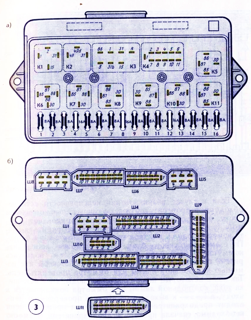
Rice. 3. Mounting block of fuses and relays 17.3722 of a VAZ-2108 car:
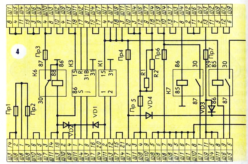
Rice. 4. Diagram of internal connections
If, in the event of a malfunction, there is a need to check the corresponding circuit in the mounting block, it is necessary to general scheme electrical equipment of the car or the power circuit of a faulty consumer, find the numbers of inputs and outputs of this circuit in the mounting block. According to the scheme of the mounting block (Fig. 4), it is possible to trace the switching of this circuit inside the block. Then, using Fig. 3, b, find these pads and plugs on the block and check the circuit using a test lamp or an ohmmeter. Since diodes are included in some circuits, the “+” of the current source, test lamp or ohmmeter is connected to the input, and “-” to the output of the circuit. If the circuit under test includes a fuse or relay, then to check the circuit, you must first check the fuse, and install jumpers instead of the relay: one instead of contacts and the other instead of a coil.
The entry, for example, Ш1-2 means: plug block No. 1, output No. 2. The entry K1.15-K11 in the "Contacts ..." column means that you need to connect the plugs "15" and "1" of the relay socket K1 with a jumper. Jumpers can also be installed instead of a faulty relay.
For example, you need to check the brake light circuit on a VAZ-2108 car. Having found the brake light switch on the general electrical equipment diagram, we see that two wires are suitable for it: white and red (magenta). The first of them is included in the block Ш4, the second - in the block Ш2.
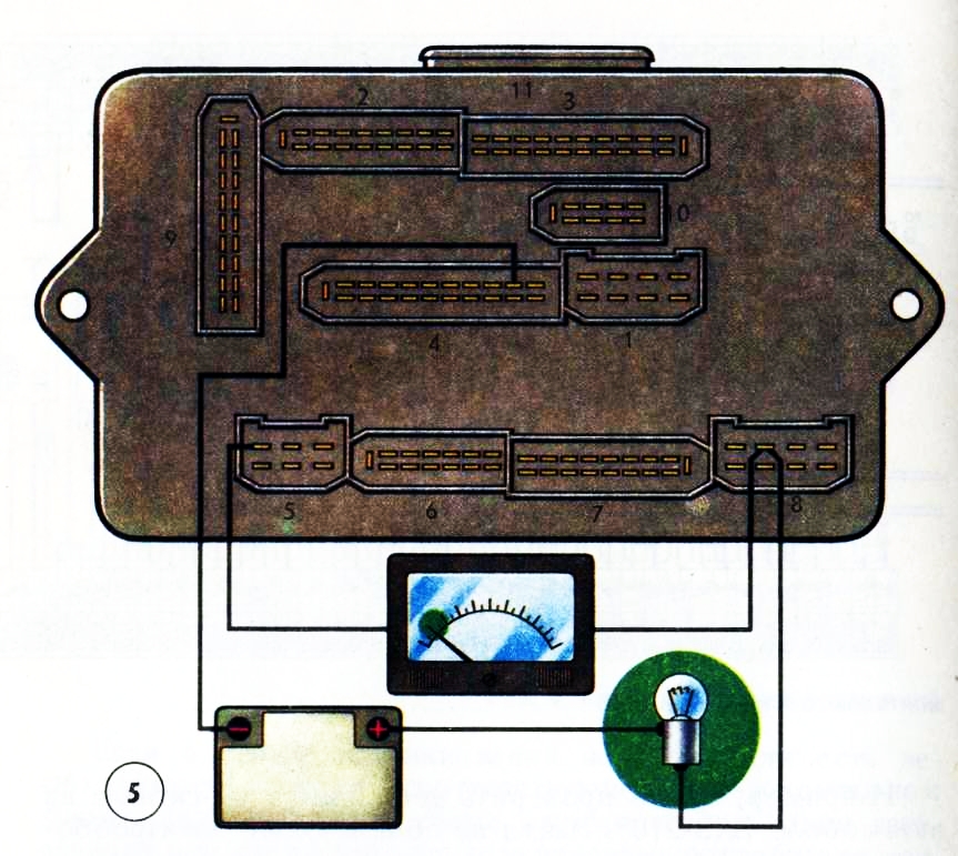
Rice. 5. Checking the mounting block of the test lamp and an ohmmeter
In the same place or according to separate wiring diagrams, usually given in repair manuals, we see that the white wire is connected to terminal No. 10, and the red wire to No. 3. According to the switching circuit of the mounting block, also available in the repair manuals, we find that power is supplied from the output Ш4-10 and it, in turn, is connected through the Prb fuse to the closed outputs Ш8-5, Ш8-6 and Ш8-7, two of which are used to supply power from the generator (battery). In the same place we find that through the output Ш2-3 and further Ш9-14 current is supplied to the lamps in the rear lights.
If the fuse is in good condition (usually you need to make sure of this right away, using the fuse table located, for example, in the “Car Operation Manual”), we connect a test lamp (Fig. 5) to terminals Ш4-10 and Ш8-7 (Ш8-5, Ш8-6). Similarly, we check the circuit of the mounting block between the terminals 1JJ2-3 and Ш9-14. If there is an open circuit in the circuit, you need to disassemble the unit and solder the broken section of the board (you can solder the conductor parallel to it) or replace the printed circuit boards.
Another example: you need to check the dipped beam circuit of the right VAZ-2108 headlight in the mounting block. According to the table of fuses, we find that the low beam thread of this headlight is protected by a Pr 16 fuse. In fig. 4 it can be seen that this fuse, on the one hand, has an output to sh5-6 and sh7-4 (empty), and on the other hand, it is connected through the contacts of the KN relay with power (pins Sh8-7, Sh8-5, Shch8-6, as and in the previous example). In turn, the KP relay coil is connected to the Sh4-12 output (to the steering column-left light switch) and the mass of the unit - the ShZ-5 and Sh10-5 outputs.
To check these circuits, instead of the relay, we put two jumpers: 30-87; 85-86. Then we connect an ohmmeter to the conclusions Ш8-7 (Ш8-5, Ш8-6) and Ш5-6. The resistance should be close to zero. Similarly, we connect an ohmmeter to the conclusions Ш4-12 and ШЗ-5 (Ш10-5).
Obviously, the use of a control lamp in the first example, and an ohmmeter in the second, is equivalent.
On a car, to check the health of the relay, for example, K11, it can be replaced with a similar one, for example K5. If, after replacing the relay, the headlights turn on, then the unit is OK, and the replaced relay is faulty. Instead of a faulty relay, you can leave a jumper, but keep in mind that in this case the contacts of the headlight switch will be overloaded, which will cause them to oxidize. Detailed testing of various relays is described in the relevant sections of the book.
To Category: - 1Domestic cars
The electrical system of a car, figuratively speaking, is a complex of a power plant and a network of consumers adapted to the special requirements of the system. Distinguish between electrical equipment of the engine and electrical equipment of the car.
Below, only the electrical equipment of the car is considered, in particular, the main network of consumers, consisting of lighting and signaling devices, glass cleaner and washer, radio, switching devices, electrical wires, as well as battery mounting parts, since the latter are installed on the body. Recall that other parts of electrical equipment (ignition coil, voltage regulator, relay, etc.) are attached to the body, but they do not require special constructive solutions. With the existing variety of electrical equipment, we will focus only on the most important, concerning the design and design of the body. Corresponding "electrical" problems are described only in connection with the above.
Outdoor lighting and light signaling system
At night and in poor visibility, vehicle lighting has a dual function: to help you see and be seen. Accordingly, a distinction is made between headlamps for the first task and lamps for the second task. The car usually has:
- headlights with high and low beam;
- additional fog lights or high beams are possible;
- parking and marker lights;
- rear lights and rear fog lights;
- license plate lights;
- reversing lights.
Light signaling includes:
- direction indicators front and rear;
- alarm system;
- braking signal.
Only prescribed or approved headlights and lamps may be fitted to the vehicle. There are many international regulations regarding the location, relative positioning of headlights, their lighting characteristics and visibility. In principle, a characteristic symmetrical arrangement of signals must be observed in front and behind the vehicle, i.e. the main headlights and lamps must be located symmetrically with respect to the longitudinal axis of the vehicle and approximately at the same height. In most countries, headlamps and lanterns are subject to classification and testing to meet national requirements. In order to simplify this process, as well as for constructive and stylistic reasons, it is very often preferred to combine lighting devices into one unit; this greatly facilitates the installation of lighting devices in the body. The existing variety of possibilities and forms allows us to give only the most general information on the design of lanterns, headlights and blocks.
The unit should have simple, as even as possible, mounting surfaces that are easy to mount and seal.
The comparison shows the advantage of the American low beam lighting system in terms of brightness and illumination (with a greater risk of glare) is exactly the same as in relation to illumination with a European four-head lighting system with 146 mm headlights, made in imitation of the American system. By using halogen lamps, this disadvantage can be reduced by ensuring easy replacement, preferably using the unit mounting from the outside (screwing from the inside); since at present almost all appliances are made hermetic, openings in the body should be large enough to allow access to the appliances from the inside (for example, to replace the lamp) and to facilitate the laying and checking of electrical wires.
For current rectangular headlamps, it should be ensured that the width and height of the headlamp have a ratio acceptable to obtain the required lighting performance, and that it remains possible to install headlight lamps that comply with American Requirements (two headlamps with a diameter of 178 mm or four headlamps with a diameter of 146 mm , or a rectangular headlight 114X152 mm), in the same cutout on the body. Recall that round headlights make better use of the luminous flux (normalized to the diameter of the reflector) and, for reasons of visibility and less dazzle for oncoming drivers, the reflective surface illuminated in the low beam should ideally be 150 cm2, which corresponds to a headlamp with a diameter of approximately 190 mm.
In rectangular headlights, according to research by Bosch, the determining parameter for low beam illumination is the width of the reflector (the diameter of the reflector truncated at the top and bottom). Therefore, small headlights should not be used. The headlights must have a diameter (equal to the width) of at least 190 mm and a height equal to 0.8-0.65 of the width. In the case of using a headlight lamp, it should be borne in mind that the sidelight (parking light) and direction indicator must be installed separately.
The headlamps can be fitted with two tungsten filament bulbs, as well as hologen bulbs (which is preferred). When using four headlights (such a system developed in the USA), you should pay attention to the following: in the European version of the low beam, as opposed to the American one used in headlight lamps, to obtain luminous flux only the top half of the reflector is used, resulting in less glare from these headlights. Illumination and visibility in this case are greatly reduced, despite the increased electrical power light threads. Therefore, in Europe, it is not recommended to use 146 mm headlights adopted from the USA (due to their easy replacement). Their installation is justified only if used halogen lamps. It is better to provide for the installation of larger dipped beam headlights. The diameter of the headlight in the plane of the exit of the light beam should be approximately 180 mm. The dipped and main beam headlights can be located both horizontally in a row one next to the other, and vertically one above the other.
Since, with the asymmetric dipped beam adopted in Europe, the boundary between light and darkness is very clearly defined and its position depends on the position of the headlights in height, the headlight range should be easily adjusted without the use of a special tool, preferably from the driver's seat using remote control. Legislation requires compliance in EEC countries with certain limits for the inclination of the dipped beam beam, regardless of the vehicle load. If for this no special measures are taken for the design of the vehicle suspension (for example, to provide for adjusting the level of the body), then these requirements can be observed only by introducing manual or automatic adjustment of the illumination zone. In the process of designing the body, it should be possible to install such an additional device. In the same way, from the very beginning of the design of the body, the possibility of installing more and more popular headlight washers and cleaners, which are powered by one or two small electric motors, should be considered. It is necessary to ensure that they have easy access.
Many experimental attempts and studies are known to overcome the main drawback of the European low beam - high dependence on the position of the headlights - by using other systems, as well as to prevent glare. The so-called polarized light provides ample opportunities for this. Although technically this question can be completely solved, however, in the practical introduction of polarized light, such significant difficulties arise (for example, mixed traffic, re-equipment of the park) that they cannot be ignored.
In fact, with the right headlights, additional headlights are not needed, and in part even harmful, since they can hardly be used with an ever-increasing traffic density. The use of additional high-beam headlights is justified only in special cases of operation (driving at night, in sports cars). It should not be forgotten that the difference in light intensity between the far and near light is very large. This makes it difficult to adapt vision, and hence visibility. Additional headlights (only allowed in pairs, they should not be too close to the longitudinal axis of the car and in no case should they block the openings for fresh cold air.
In contrast, it is useful to have paired fog lights. To avoid dazzling drivers of oncoming vehicles, fog lamps should be located as low as possible, at a distance of no more than 40 cm from the outer contour of the car, so that they can be used simultaneously with the parking light. Only in this case, the fog lights will to some extent correspond to their intended purpose. When designing, it is advisable to provide for the possibility of installing fog lamps in the front of the car in order to exclude unqualified installation during installation at the request of the buyer. Quite a good solution is to place the fog lights under the front bumper. Recall that the headlights can be closed or recessed, in the USA this is only permissible if certain regulations for their operation are met.
Clearance lamp, brake lamp, reversing lamp and rear turn signal, and reflectors most often combined into one unit, easily installed on a car. From the point of view of lighting engineering, it would be better to group these lighting devices into two nodes (direction indicator - position lamp - reflector and brake light - reversing lamp). When combining a position lamp and a stop lamp, it should be taken into account that there must be a ratio of 1:5 between the luminous intensity of these devices, which can be achieved using a 5/18 W double-filament lamp and an optimally designed reflector. The left and right position lamps must be protected separately.
Mandatory lanterns (lantern) for lighting the rear license plate must provide sufficient visibility of the license plate and must not radiate light backwards. This should be taken into account when designing and placing these lights. The location of the lights is chosen arbitrarily, you can even use the back door if the side lights are firmly fixed. In order to accommodate a film license plate, the installation of which will be introduced in the near future (probably within the framework of the EEC, at least in Germany), it is necessary to provide a flat area of sufficient size on the rear panel (width 520 or 340 mm, height 120 or 240 mm) .
When installing rear lights, which are legal in many countries (required in the US), care should be taken to ensure that they do not dazzle drivers of vehicles moving behind. This can be achieved by using an appropriately designed reflector and tilting the light beam down. In some countries, one fog light is allowed, which can be placed on the left side and separate from the rear light. The fog lamp is switched on separately from the other lamps (only together with the headlights) and is controlled by the yellow control lamp on the instrument panel. However, according to the EU Directive, two fog lamps are required as standard, which is why these lamps are now usually integrated into the rear lamp.
Switching elements
Turning on the headlights, parking lights and lamps is best done with a single lever switch. However, it is possible to provide separate switches for the parking light and headlights (with a mechanical interlock that turns on the parking light whenever the headlights are turned on). Switching the headlights with the turn signal combination lever is now standard and should always be provided. With the help of this lever, as you know, the direction indicators, the windshield washer and wiper system, and the headlight signaling are usually switched on. The direction indicators are activated via an electronic relay that provides a flashing mode of operation, if appropriate, this relay also provides an alarm system. The latter, however, must be switched on using a separate switch with a red control lamp. The relay must give optical and acoustic control signals and is therefore located in the passenger compartment. Note that the turn signal thermomagnetic relays cannot control the alarm system, so a second relay is needed (you should provide a place for its placement). The hazard warning switch can be located in any suitable location, such as on the steering column.
Sound signals
prescribed in all countries mandatory installation sound signal, most countries have sound intensity regulations. The use of signaling devices with different tone alternations for private cars is prohibited in Germany. When placing sound signals, care should be taken to ensure that body parts do not interfere with the propagation of sound. The horns can be placed behind the grille where they are protected to some extent from pollution and precipitation. The audibility of the signals is highly dependent on the speed of the vehicle. There are two types of beeps that differ in their sound.
The horn membrane has a specific fundamental sound frequency (approximately 400 Hz) and radiates in the high-pitched region (approximately 1800-3500 Hz). Therefore, the tone of the horn signal is harsh and piercing at the same time. To improve the sound, the horns are used in harmonically coordinated (third) pairs. With the help of an elastic suspension, the influence exerted on the sound by vibrations of body parts and their rattling (exclusion of acoustic and mechanical short circuits) should be prevented, in connection with which the free propagation of sound is of particular importance.
Fanfare (electro-pneumatic horn) has a wide frequency range, since in this case the air column oscillates in a pipe (spiraled). Thanks to this, the tone is softer and more pleasant, but, contrary to the general opinion, less penetrating. In addition, fanfares are not so sensitive to vibration lock. All horns (Actuated by a switch through a relay, as they are highly voltage dependent and very susceptible to poor contact.
windshield wiper
Mandatory installation of a windshield wiper with the appropriate drive is prescribed in all countries, however, the presence of a washer is not required everywhere, although it has long been a part of the standard equipment of the car. The cleaner uses an electric drive, most often with two speeds.
Since visibility is severely reduced and sometimes completely lost due to dirt on windows, rain, etc., a well-functioning wiper and washer is an important factor in improving safety. The requirements for the minimum size of the area to be cleaned (as well as for the defrosting zone) first appeared in the USA (Federal Standard 104) and were soon adopted into UNECE Regulations and EEC directives.
The field of view is divided into several zones, each of which has its own degree of cleaning, expressed as a percentage. Thus, the choice of parameters of the cleaner and washer to a large extent depends on the size of the glass, its shape, and position relative to the driver's seat (center of the eyes).
With modern windshield shapes, the requirements mentioned above can best be met with equally or oppositely moved wiper arms. The brushes are driven by an electric motor with a built-in worm gear. The position of the swing centers (arms) and their length are largely determined by the desired (and prescribed) cleaning area, as by the length of the brushes. By changing the inclination of the brush relative to the arm, cleaning in corners can be improved and a more acceptable starting position can be obtained. Heavily curved and non-spherical glasses only by using brushes with an even distribution of contact pressure (Tricot principle) and by matching the curvature of the brush to the curvature of the windshield as much as possible, it is possible to obtain the required cleaning zone.The contact pressure at the end of the lever is approximately decreases, so it would be necessary to provide special pressure pads, which, however, impair visibility.
The slope and shape of the windshield have a strong influence on the performance of the wiper, which should be checked; at high speeds of air flow in the wind tunnel. The power consumed by the wiper fluctuates greatly, since the shear resistance of the brushes is significantly less when the glass is wet than when the glass is almost dry or dry. In accordance with this, the moment of braking of the electric motor and the forces in the levers and hinges also change greatly. The moment (according to Bosch) varies from 7 to 25 N-cm. The dynamic forces in the hinges are also very high. It is more expedient to use ball joints with Teflon liners, which do not require lubrication and provide a clear spatial movement of rods, which, as a rule, are not parallel to the axes of the wiper arms and the drive crank. It is best to place the wiper elements in an easily accessible place under the hood, and it is preferable to pre-mount the system (electric motor - traction - wiper arms) on a stable supporting frame, which is then installed on the body together with rubber soundproofing gaskets. Thus, an accurate fixation of the relative position of the elements and an optimal distribution of forces are achieved.
Recall the design common in the USA with a closed initial arrangement of the wiper arms, which, for inexplicable reasons, has not received distribution in Europe. The automatic intermittent operation of the cleaner in light rain or damp fog is very practical. In this case, the wiper is switched on at regular intervals (sometimes adjustable). This design requires either a dedicated wiper switch position or a separate intermittent wiper switch (with adjustable spacing) for which space must be allocated in the part of the instrument panel where the switches are located.
Glass washers
The washer has either one central jet that sprays water in two directions, or two separate jets, which are usually attached to the hood, but it is better to attach them to any rigid body part located in front of the wind window; they must be adjustable so that the direction of spray can be optimized.
Washers must be powered by an electric pump; by a certain combination of switches, the cleaner is switched on after water is sprayed and the brushes make several strokes. The pump and time relay are most often attached to the washer reservoir. The latter, in order to prevent the liquid from freezing, is best placed in the engine compartment.
Since the pipelines of the system are constantly filled with liquid, the possibility of freezing them is very high, so it is necessary to add antifreeze to the liquid used for washing glass. Often this is not enough, since the antifreeze evaporates in the area of \u200b\u200bthe jet holes. Therefore, it is recommended to use a recessed installation of jets. The mentioned recessed installation of the cleaner is very rational, especially in the case when warm air escapes from the engine compartment through the gap formed. US Federal Standard 104 contains requirements for the minimum washable area (in % of glass area cleaned), as well as for reliable operation in frosty conditions. These requirements are very difficult to fulfill without making special design decisions. Therefore, heated jets were developed, the use of which eliminates freezing.
A few more words about headlight washer systems. Their design depends entirely on the shape and placement of the headlights. The minimum requirements for headlight washers, similar to those for windshield washers, are based on light transmission measurements during and after cleaning and washing the headlight glass.
Car radio, antenna, interference suppression
A car radio has completely different operating conditions and functions than a conventional one. First, the sensitivity, selectivity, interference rejection, gain, and AGC system, due to the lower antenna efficiency and highly fluctuating input energy, must be much higher; secondly, the influence of atmospheric disturbances, thermal and mechanical loads, as well as the labor intensity of use should be as minimal as possible.
Simplify the installation of radio equipment on a car by separating the radio receiver from the loudspeakers, if they are small. The development of semiconductor technology and electronics contributes to the creation of equipment of any power. Despite this, it cannot be ignored that at present, in the conditions of driving a car, the reception of radio transmissions serves more for obtaining information than for satisfying cultural needs, and the quality of reception is highly dependent on the level of noise generated by the movement of the car. The use of additional devices specially designed for receiving radio transmissions in traffic only emphasizes this phenomenon.
To simplify the use, only devices with a fixed station tuning should be used, preferably with an additional transmitter station finder, since manual control of the radio receiver is an element that increases the danger of movement.
Consider especially the placement of the antenna and loudspeakers. Significant improvement in reception quality can be achieved if the following guidelines are taken into account.
The antennas of car radios are the more effective, the farther they are removed from the mass of the car (contour). For these purposes, whip antennas that extend to a height of approximately 0.9 m are best suited. In addition, such antennas are insensitive to the direction of radiation of the transmitting station. As a result, roof-mounted fold-out antennas often provide better reception than conventional windshield-mounted, telescopic, and folding whip antennas. However, the quality of radio wave reception is so dependent on the vehicle's own parameters that the most suitable antenna position should always be determined from test results. It goes without saying that the antenna should be as short as possible and noise-resistant. An antenna located on the side and inaccessible from the driver's seat must have an automatic electric drive. When matching the antenna, as well as the radio receiver, preference should be given to the VHF range and medium waves.
Loudspeaker placement, especially stereo radio equipment, should be carefully considered. Many years of practice have shown that subjectively, the sound coming in the direction of sight is perceived better. Therefore, it is best to install one loudspeaker in the center of the instrument panel, or to increase the completeness of the sound (or with stereo radio equipment) - one loudspeaker each in the left and right parts the instrument panel so that the sound comes at an angle to or away from the instrument panel.
Quite acceptable is the location of the loudspeakers one by one in the left and right parts of the roof frame, approximately in the middle of the cabin. By appropriately designing the loudspeaker grille, the sound can be propagated forward and backward. The loudspeaker should, if possible, be placed in a soundproof enclosure to prevent acoustic low-frequency short circuiting of the waves generated by the rear side of the cone. If the speakers are located in the front and back parts cabin, it is necessary to provide for the adjustment of sound distribution. When creating stereo sound, this must also be observed for the left and right speakers.
All this data is given because the bodybuilder must know the requirements for the installation of radio equipment and foresee the place for its placement.
The quality of radio reception in a car depends on the general criteria mentioned above and on shielding (suppression of interference sources). In addition to power lines, electrified railways and other interference coming from outside (including other cars), the main source of interference is the ignition system of carburetor engines. However, wiper motors, electrostatic charges, and poor contact and ground connections metal parts bodies (bumpers, fenders, hoods) can cause functional interference. Therefore, so-called suppression of interference from the ignition system by means of resistors is prescribed for all vehicles. For the radio to work without interference (as, indeed, for all radio equipment in general), this is not enough, it requires additional funds interference suppression from the generator, its regulator, the wiper motor and other electric motors. Sometimes, in addition, it is necessary to provide a ground wire between the hood or trunk lid and the body. The bodybuilder must take into account the fact that large parts having a threaded fastening on the body must have close contact with it, and the contact surfaces of the part and the body must be free from enamel (sometimes additional tinning should be provided). In addition, there must be no corrosion.
Car electrical circuits, battery mount
Car electrical circuits I serve to distribute the current between individual devices and, in accordance with the many consumers, they are very branched. A complete picture of the electrical equipment of the car gives a general electrical circuit.
The electrical network of the car is mainly single-wire, the negative pole of current sources in Europe is connected to ground.
When placing the battery, it should be ensured that it is connected, if possible, with a short wire to the starter and located in an easily accessible place. For safety reasons, the battery should not be placed too close to the front edge of the vehicle. In addition, care should be taken to ensure that body parts do not corrode from the emitted vapors of acid and gases. To do this, they must be protected or closed. The fastening shall be strong enough that the battery will not come off during the impact test. The currently accepted bottom attachment with a welded or screwed holder adequately satisfies this requirement. It is best to have the battery rest on the lip of the front wheel mudguard or on the bracket attached to it, or on the front engine bay shield if there is room for that.
Usually not all branches of electrical circuits are protected by fuses. The main energy consumers are grouped in such a way that 8-10 fuses can be dispensed with, and additional energy consumers (radio, fog lights, etc.) are protected separately. Some devices, such as headlights, are often not protected, because experience shows that they rarely fail, and in the event of a malfunction, it is easy to find (for example, broken lamp filaments). If it is nevertheless decided to protect the headlights, then a fuse must be provided for each thread. The fuse box should be located in an easily accessible place in the passenger compartment or in the engine compartment. The block must be marked with information about the protected circuits so that it can be used when searching for the cause of the failure. Currently, the fuse box is combined with a diagnostic block and placed in the engine compartment, in addition, this place has good access to the relay. The choice of fuse (5.8 or 15 A) depends on the current consumed by the device, which is also decisive when choosing the cross section of electrical wires. Knowing the usual voltage of the on-board network for a car, equal to 12 V, you can easily calculate the current consumption.
Overloaders, used in the USA instead of fuses, are not widely used in Europe for cost reasons.
Electrical wires
The electrical wires must have a cross section corresponding to the current drawn by the connected appliances, and the voltage drop due to the resistance of the electrical wires must be minimal.
AT general case use electrical wires with copper conductors, the cross-sectional area of which is 1-2.5 mm2. Wires with a cross-sectional area of less than 1 mm2 are not recommended, as they have insufficient mechanical strength.
A large number of electrical wires, a large branching of the vehicle's electrical network, as well as the requirement for ease of installation lead to the need to combine individual electrical wires of certain groups of electricity consumers into bundles, for example, for the front of the car (headlights, engine compartment lighting, sound signals), for power supply to the passenger compartment (devices, switches, ignition lock) and for the rear of the vehicle (parking light, brake light, turn signal and reversing lights or rear lights), which are connected to each other using multi-terminal plugs. This makes troubleshooting easier. A useful innovation is the introduction of a diagnostic system into the electrical network, the connector of which is located in the relay and fuse box, which allows you to check the performance of the most important units.
Recently, great efforts have been made to simplify on-board electrical network by eliminating individual electrical wires and introducing a central wire used for a multiplex (single-wire) distributed consumer control system, similar to how it is done in telephone communications. Although these developments are still in their early stages, they are of particular interest, since their implementation will increase the reliability of operation and, possibly, reduce costs. This would significantly simplify the vehicle's on-board network and lead to improved monitoring and diagnostics of failures of individual devices. In the future, this simplification is all the more necessary, since electronic control and monitoring devices require a developed electrical network that is independent of the vehicle's power circuits.
A modern car has a complex electronic “stuffing”, which is called in one general word “electrical equipment”. Vehicle electrical equipment- these are its lighting devices, engine start mechanism, car security, heater and air conditioning, etc. Electricity is generated from sources (battery and generator) and transmitted to consumers.
Current consumers in the electrical system of a passenger car are: an engine start system, a car ignition system, a lighting and alarm system, instrumentation and additional equipment, which may differ for each car.
We have already met with the engine ignition system earlier (see Chapter 2, section "Ignition System"). We only recall that for the operation of an internal combustion engine, a spark plug is needed, which gives an electric spark, from which the working mixture in the cylinder ignites (glow plugs are used in diesel engines). And this spark appears due to the presence of an electrical system in the car. We will get acquainted with other consumers of electricity in this chapter. In other words, next we will learn about how Electric Energy modern car.
Sources of electric current
The electric current in the car is generated from two sources: the battery (accumulator) and the generator.
Battery task(Fig. 4.1) - provide electricity to the appropriate vehicle equipment when the engine is off, as well as when the engine is running at low speeds. The battery is usually located in the engine compartment on a special metal shelf, but in some car models it can also be installed in the passenger compartment.
The battery has "plus" and "minus" on the corresponding poles. The negative pole is connected to the car body and provides, as the drivers say, "ground". The positive terminal is connected to the electrical circuit of the car, through which electricity is transmitted.
The battery includes six separate batteries located in one housing and connected in series to form a single battery. electrical network. Electrochemical processes take place in each battery, as a result of which a current of 2 volts is obtained. It is easy to calculate that in total, a direct current of 12 volts is formed on the poles of the battery (six batteries of two volts each).
The battery is marked with the standard pattern. For example, marking 6ST-60A stands for:
6 - the number of batteries in the battery (for all cars, this figure is unchanged);
ST - type of battery, in this case - starter, which allows you to start the engine with the help of a powerful consumer of electricity (starter);
60 - battery capacity, which is measured in ampere-hours (in this example, 60 ampere-hours);
A is the designation of the material from which the battery case is made (in this example, polypropylene).
The more power required to start the engine, the more capacity the battery must have. For standard Soviet Zhiguli, batteries with a capacity of 55 ampere-hours were used. But such a battery may not be enough to start diesel engines - they need at least 60-65 ampere-hours.
Usually new battery serves for 6-7 years. After that, it must be replaced, although sometimes you can extend its life by periodically recharging it with a special charger.
Generator(Fig. 4.2) is a source of electric current that provides electricity to all consumers when the engine is running at high and medium speeds. In addition, the most important function of the generator is to recharge the battery (also with the engine running). Without a generator, a new battery will be discharged very quickly and its use will become impossible.
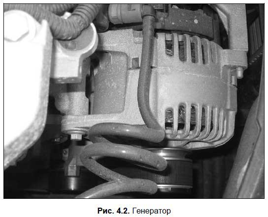
AT electrical circuit car generator is connected in parallel with the battery. Therefore, it will supply consumers with electric current and charge the battery only when the voltage it generates is greater than the voltage supplied by the battery. This happens when the car's engine is running at a speed above idle: after all, the voltage of the electric current that is produced by the generator directly depends on the speed of rotation of the generator rotor, which is driven by the engine.
It should be noted that sometimes the voltage generated by the electric current generator may be greater than necessary. To prevent this situation in the car, a special device called a voltage regulator is used. This device operates in tandem with a generator, limiting the voltage of the current it produces and regulating it in the region of 13.6-14.2 volts. The voltage regulator can be built into the generator, or it can be located in the engine compartment separately from the generator.
There is a specially designed bracket for mounting the generator on the engine. The generator is driven by the engine crankshaft through a belt drive. On many machines, with the help of one belt, a drive is created from the crankshaft to the generator, the constantly running fan and the water pump (pump), i.e., all these units work as if in one bundle, although they perform completely different functions. However, this is not necessary - often the generator has a separate drive belt. In any case, it is necessary to periodically check the belt tension and, if necessary, adjust it by tilting the generator housing. Remember that an insufficiently tensioned belt, firstly, makes unpleasant whistling and creaking sounds during operation, and secondly, it quickly fails.
On the instrument panel of any car, there is always a red battery charge light. It always lights up when the ignition is turned on and goes out after starting the engine. If, when the engine is running, the light does not go out, this indicates problems in the power supply system (probably the generator has failed).
Lighting and signaling devices
Lighting devices are designed to indicate the dimensions of the vehicle when driving at night and in conditions of insufficient visibility, as well as to illuminate the road and the interior of the car (engine compartment, passenger compartment, trunk). Lighting devices are headlights (block headlights), license plate lamps, interior lamps, trunk lamp, engine compartment (engine compartment) lamp and taillights.
Block headlight (Fig. 4.3) consists of a body, diffuser and reflector. Inside the housing there is a lamp inserted into the socket, which can operate in two modes: low beam headlights and high beam headlights. The dipped or main beam is switched on using a switch located in the passenger compartment. There is also a light bulb inside the headlight. side light, which is designed to indicate the dimensions of the car, if necessary (there is also a toggle switch to turn on the dimensions).
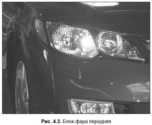
Modern block headlights often also contain a turn signal bulb, but it can also be located separately - it all depends on the specific car model.
Rear lights (Fig. 4.4) in modern cars are also usually made in the same housing.
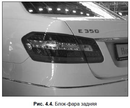
Rear light includes:
Stop lamps (turn on automatically when the driver presses the brake pedal, and turn off when the pedal is released);
Reversing lamps (light up automatically when the driver turns on the reverse gear, and go out when it is turned off);
direction indicators;
Parking lights.
The driver turns the direction indicators on and off using a special switch, which is usually located on the steering column. All direction indicators simultaneously work when the driver turns on the alarm (a special button is designed for this). The procedure for the use of emergency light signaling is regulated by the current traffic rules.
An audible signal is a signaling device designed to audibly alert other road users of imminent danger. It is activated by pressing a special button or key, usually located on the steering wheel. The procedure for applying the sound signal is prescribed in the traffic rules.
Engine start system
To turn on the engine, the engine start system is designed, consisting of an ignition switch, a starter with a traction relay, a starter drive mechanism and a starter enable relay.
The engine is started using starter(Fig. 4.5).
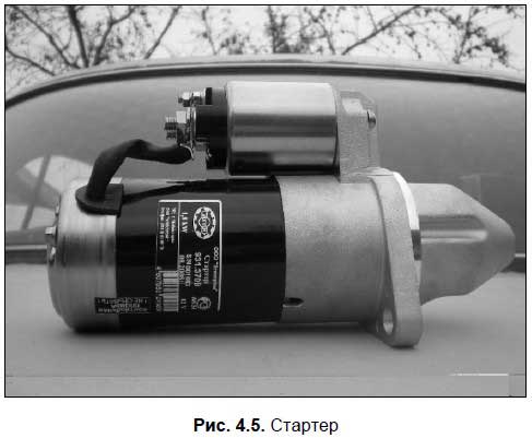
This device is a DC electric motor. When the driver turns the ignition key to the "Start" position, electricity through the relay is supplied from the battery to the starter windings. As a result, the traction relay is activated, the special starter gear engages with the engine flywheel and turns it. Since the ignition is already on, the engine will start and run.
Note that the starter is used solely to start the engine; the rest of the time this device "rests". The process of the starter can be divided into three key stages.
First, a special gear located on the starter armature shaft engages with the engine flywheel ring gear (this is possible due to the drive mechanism). Visually, this can be represented as follows: take two gears, one of which will illustrate the flywheel ring gear and the other the starter gear, and engage them. If you turn the “starter gear”, then the “flywheel ring gear” will certainly turn.
Next, the starter shaft, together with the gear engaged with the flywheel, begins to rotate, as a result of which the flywheel rotates, and therefore the engine crankshaft also rotates, after which it starts.
Then, when the driver has started the engine and released the key in the ignition, turning off the starter (the key in the “Start” position can only be held by force, since it automatically returns back), the starter gear disengages to the side (the gear teeth will remain at the same level, but only to the side). It is in this position at all times when the engine is running or off, and engages with the flywheel only when the driver turns the ignition key to the "Start" position.
Remember this.
Immediately after starting the engine, turn off the starter by releasing the key in the ignition. Forcibly holding the key while the engine is running in the “Start” position can quickly disable the starter: a heavy rotating flywheel rim will at least simply “grind” the starter gear. It is possible that the starter will receive other damage (the traction relay will burn out, etc.). For the same reason, in no case should the starter be turned on while the engine is running.
With proper use, the starter is a fairly reliable device that can serve throughout the entire life of the car.
Instrumentation
To promptly inform the driver about the condition of important components and assemblies of the car, the current speed limit, the availability of fuel, the distance traveled and other important factors in the car, instrumentation(abbreviated KIP). The instrumentation is located in a place convenient for the driver's view, namely, on the instrument panel (instrument panel), located immediately behind the steering wheel (Fig. 4.6).
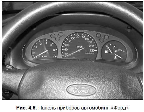
A typical instrument panel contains control lamps, an odometer (a mileage counter, and separately for total and daily mileage), a coolant temperature sensor, a speedometer, a fuel level sensor and an engine speed indicator (tachometer). Also, the instrument panel may include other instrumentation - it depends on the car model.
Everyone should know this.
Valid for all KIP general rule: when the engine is running, in no case is it allowed to glow any red light (indicator) or find the arrow of any indicator in the red sector. Such indications of the instrumentation inform the driver about the presence of serious malfunctions in the corresponding unit, and the vehicle cannot be operated until they are eliminated.
Indicator lamps provide the driver with information about the current state of systems, components and assemblies. In particular, when the ignition is turned on, the red lamps for battery charging and oil pressure light up - they should go out after starting the engine. If the car is on the "handbrake", then on the instrument panel with the ignition on, the corresponding red light will light up, which will go out only after the parking brake system is turned off.
When you turn on the dipped or main beam headlights, the lamps on the instrument panel light up, respectively, green and blue flowers. When the driver turns on the direction indicator or emergency gang, the corresponding indicator flashes on the instrument panel, which is accompanied by characteristic audible clicks.
Tachometer(Fig. 4.7) shows how many revolutions per minute the engine crankshaft makes in the current mode of operation. Usually it is measured in thousands, so the dial contains the numbers 1, 2, 3, etc., and when the hand points to a number, you should multiply it by 1000.
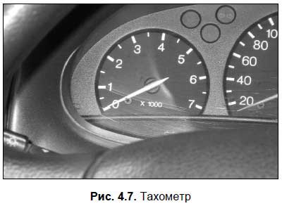
Fuel level sensor(Fig. 4.8) informs the driver about the amount of fuel available in the fuel tank at the moment. When there is too little fuel left, the arrow approaches the red sector, and in many cars, the corresponding lamp lights up additionally (sometimes it looks like a gas station). Do not ignore the alarm readings of the sensor - otherwise you risk stalling on the road due to lack of fuel in the fuel tank.
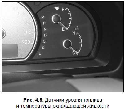
Odometer shows the number of kilometers traveled by the car, and in modern cars separate meters are designed for the total and for the daily (or for any arbitrary time interval) run.
Speedometer(Fig. 4.9) is a device that informs the driver about the current speed mode (in other words, at what speed the car is currently moving). The indications of this device are extremely important for choosing the correct speed and for preventing violation of the speed limit established on this section of the road by the current Rules of the Road.
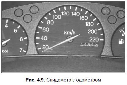
coolant temperature sensor(see Fig. 4.8) informs the driver whether the engine cooling system is functioning normally. We have previously said that the operating temperature of the coolant should be between 80-90 degrees Celsius. If the sensor arrow has moved to the red sector, it means that the liquid temperature is approaching 100 degrees or has already reached it. In such a situation, immediately turn off the engine and let it cool down.
Additional equipment of a modern car
Additional vehicle equipment is intended mainly to improve the comfort and convenience of the trip, as well as to provide the necessary driving conditions. Among the most common types of additional equipment are: interior heater, air conditioner, radio, windshield wiper and washer, glass, mirror and seat heating devices, electric window and seat lifts, electric headlight corrector, headlight cleaner and washer, refrigerator, satellite alarm system, etc. .
The interior heater is simply called a “stove”, without it in most Russian regions you can operate a car for no more than three to four months (otherwise you can just freeze). Also, the heater is used for blowing windows, eliminating the condensate that has appeared on them (the so-called "fogging"). When a car engine overheats, turning on the stove at full power sometimes helps.
The windshield wiper and washer provide visibility when driving in rain or snow, or when driving on muddy roads.
Please note.
Traffic rules prohibit the operation of a vehicle if it does not have windshield wipers and washers designed for it.
Not all cars are equipped with a glass and mirror heating system (this does not apply to the rear window - it is heated in all modern cars). These devices help to quickly remove ice and snow from car windows and mirrors. Not all cars also have a seat heating system, but if it is, then getting into a cold car in winter will be much more pleasant.
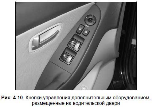
Also a popular device is air conditioning. In hot weather, this device is able to turn a tiring ride in a car under the scorching sun into a real pleasure. The presence of an air conditioner is of particular importance for people who are prone to motion sickness when driving in a car (for example, the elderly or children). On the other hand, use the air conditioner with caution, as there is a high risk of catching a cold.
Electric headlight corrector (Fig. 4.11) have many modern foreign cars. This device allows the driver from his seat to adjust the direction of the headlights - higher or lower.
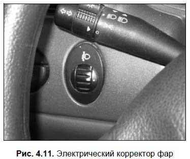
A headlight wiper and washer are not devices that every modern car should be equipped with (unlike a windshield wiper and washer). But when driving on dirty roads, these devices are very convenient, because they allow you to clean the headlights of dirt while driving.
We advise you to read
 Healthy eating scenario "Vitamins visiting children
 How to quickly and easily wake up in the morning - easy and effective tips
 Psychological characteristics of children in adolescence
 Transferring a child to another school - the procedure and necessary documents Whether to transfer a child to another school