1.1. Basic concepts and types
AUTOMATIC REGULATION
Automatic control is a set of actions aimed at the implementation of the functioning of the control object in accordance with the program and the purpose of control.
A control object is understood as a device in which the value of the required indicators of a process is maintained. The actual state of the control object is determined by one or more operating parameters y i , called adjustable values or adjustable coordinates and determining the actions of the control system (Fig. 1.1).
Do you know the methods, principles and fundamentals of automation? Update the process in which human activity will be replaced by the activity of various devices and devices! We will introduce you to the different types of control and how automation control works.
In the past, everything was controlled by hand. This, however, changed with the start of automation. Today we distinguish different types management. Control is an action on an object to achieve a given goal. However, everyone has always tried to get rid of the dull physical and mental activities, which therefore gradually began to take over the vending machines. When automatic control was replaced by manual control, we could start talking about the beginning of automation. We divide automatic control into direct and indirect.
AT in real conditions, the control object is influenced by external influences, which are called disturbances f i. Essentially, any physical quantity that characterizes the controlled object, for example, speed (linear and rotation), voltage and current, linear and angular displacements, etc. can be used as regulated quantities.
Three types of control and definition of regulation
In the first of them, the control process takes place without a power source. Currently, however, the second type of power management is commonly used and is discussed in the text below. We can share automation control with the power supply depending on whether its output is supported.
Control Control higher forms control. . Control is a method of control that cannot be controlled in any way. Regulation in automation consists in maintaining physical quantity at a constant value or at a value that changes according to a rule. The quantity values are constantly compared with the value required during the control. Any deviations are eliminated by interventions in the regulation process. The following figure clearly illustrates the difference between control and regulation.
Adjustable values y i determined by control actions U i (t) at the input of the control object. These effects cause changes in the internal state of the OS and, as a result, in the controlled operating parameters.
Typically, automatic control is carried out using automatic control devices without human intervention. The combination of the automatic control device and the control object, interacting with each other, forms an automatic control system (ACS).
Higher forms of management and artificial intelligence
The diagram shows how automation works. Source: Ivan Schwartz, Fundamentals of Automation. Higher forms of control include optimal control, adaptive control, learning, and artificial intelligence. Optimal control is as efficient as possible or, conversely, very fast. The system is able to achieve the desired properties with minimal energy consumption, always looking for the most beneficial effects and thus ensuring the best behavior of the system under given conditions.
The main types of automatic control are:
1) automatic control with an open chain of influences (hard control);
2) automatic regulation;
3) automatic setting.
Automatic control systems with an open chain of influences are usually called open. In these systems, control is carried out according to the laws; independent of the actual course of production
Development of a functional diagram of the ATS
With adaptive control, the system can even change its structure and parameters. Always adapts to the optimal control process, adapts to changes in the parameters of the controlled object. In the management process, which is called learning, the adaptive system is even more perfect. He can remember the information received and reuse it in similar situations.
Artificial intelligence is a system with the highest degree of control. An artificially created system can recognize objects and phenomena and can analyze their relationships. This creates models of the environment and makes meaningful decisions and can predict their consequences. An artificial intelligence system can discover new models and even improve its performance.
process, and is performed in an open loop in order to obtain a certain end result (Fig. 1.2, a).
Hard task at the input of the system through the control device CU and executive device(amplifier) DUT acts on the control object of the op-amp, at the output of which the value is set X exit corresponding to this task X in .
Principles of operation of the control system on the managed system
There are several ways to implement automatic control. Logical, continuous, discrete and fuzzy controls differ from each other by the principle of operation of the control system on the controlled system. What are the characteristics of each type of driving?
This occurs as a result of the deployment of computers as a controller to control computers that cannot process a continuous signal is converted into a discrete connection between inputs and outputs, as the relationship between the sequence of pulses read in the time sequence of the sampling period of the sampling time is reduced by a fast controlled process.
- The control uses two-valued variables.
- There are always only two options.
- Quantities are expressed as values 1 and 0.
- Relationships between variables are called logical functions.
- The action action is permanently set.
- The quantities change continuously over time.
- Creates a continuous link between inputs and outputs.
In such systems, the course of the process and the output controlled value are not corrected (not controlled), therefore, it may deviate from the specified mode. The control used in such systems is called open-loop control.
ACS with an open chain of influences are used to ensure a certain sequence of operation of various elements of automatic devices. In more complex cases, a program control of a process with an open cycle of influences can be carried out. An example is the control system for starting and braking engines.
The fact that the control functions are computed digitally in this case is the reason for discretization during system operation. The term discrete system itself, in contrast to a continuous system, means that the values included in the process are in the form of a sequence of pulses, which corresponds to the representation of the function only in specific and, in principle, equal time intervals. Another type of sampling, also present in digital control systems, is signal value quantization.
In real systems, the most important reason for the appearance of minimum change values in addition to the word length used in the microcontroller is the processing accuracy obtained in analog-to-digital converters. General scheme discrete control system is shown in the figure. The controller block is represented in this solution by means of a control algorithm contained in the microcontroller program. The measured quantity - which constitutes the feedback signal - is entered into the microcontroller only at so-called sampling moments, repeated with a period.
In open-loop control systems, control is carried out according to the master action, which, in general case may represent program commands.
This principle consists in the fact that in order to reduce the deviation of the controlled variable from the set value, which appears due to the inertia of the system object, the control action is formed in accordance with this action and the characteristics of the control object (Fig. 1.2, a). 
The result of the calculation of the control algorithm is also entered with a sampling rate, where it is either used in numerical form to control the executive system, or requires conversion to an analog value. Discrete digital circuits are replacing analog systems. The digital system guarantees the stability of the control parameters over time and with temperature changes, as well as the ease of changing them, even when the device is being controlled. In the course of work, it is also acceptable to change the structure of the system, which greatly increases the flexibility of management.
The control device converts and amplifies the master action and generates the control action u(t).
The control action from the output of the control unit enters the control object of the control unit and seeks to change the controlled value X exit in accordance with the driving force.
Such control is called rigid, since it does not take into account the actual values of the controlled variable and disturbing influences (the ACS parameters are considered constant).
In general, digital controllers are much more capable of using modern control methods, taking into account relatively complex mathematical operations. Optimization procedures used in digital control systems may take into account more complex criteria, such as integral criteria derived from modern state-space control structures. Due to the ease of changing parameters during system operation, controllers are created that have the property of self-tuning to the parameters of a particular object based on measurements automatically performed during startup.
BASIC MANAGEMENT PRINCIPLES
Depending on the methods of forming the control action, the following control principles are distinguished:
Disturbance control principle,
Deviation control principle,
The principle of combined control.
DISTURBANCE CONTROL PRINCIPLE
Reducing or eliminating the deviation of the controlled variable from the required value, caused by the influence of various disturbances in open systems, can be performed by applying the principle of disturbance control, discussed below. The functional diagram of the disturbance control is given in Fig. 1.2, c. The principle of disturbance control is that in order to reduce or eliminate the deviation of the controlled variable X exit from the set value, the main disturbing effect is measured F and is converted into a control action u(t) applied to the system input in order to compensate for the deviation of the controlled variable caused by the perturbation. Therefore, in such systems, the control action is a function of the perturbing action.
in systems with the principle of control by perturbation for the formation of the control action u(t) direct information about the disturbing effect is used. Therefore, in these systems, it is possible to fully compensate for the influence of the perturbing action on the controlled value X exit . The degree of compensation for the influence of the disturbing influence depends on the accuracy of the measurement of the disturbing influence and the characteristics of the op-amp.
The advantage of ACS with the principle of disturbance control is that they allow you to fully compensate for the disturbing effect. Such automatic control systems are open-loop, therefore, as in any open-loop system, there is no stability problem here.
If there are several disturbing influences in the system, all of them can be compensated separately in the same way, if it is possible to measure them. However, this complicates the system. In practice, only disturbing influences are compensated, which most sharply affect the controlled value and cause its significant deviations from the required value. Such perturbations are called fundamental. Minor disturbances are called disturbances that cause only minor deviations of the controlled value from the set value.
The disadvantage of such ACS is that they eliminate the influence of only the main disturbances. In addition, the accuracy of regulation and compensation are reduced when the characteristics of the op-amp change.
The disturbance control principle is used in systems designed to maintain a constant controlled variable.
DEFLECTION CONTROL PRINCIPLE
Automatic regulation is characterized by the fact that the control functions are dependent on the actual course of production process in order to maintain the required performance this process. Control and information about the actual values of the indicators of this process are carried out using feedback.
In the general case, such an automatic control system can be shown in Fig. 1.2, b. The system uses closed-loop control (feedback principle or deviation control). The control deviation is the difference between the actual measured value and the set value. The reciprocal difference between the setpoint and the actual value is called the control error. The control device is understood as a technical device with the help of which the control object is automatically controlled.
Controlled value X exit determined by the driving influence X in = X h at the input of the system, i.e., the influence introduced into the system and determining the necessary law of change in the controlled variable. At the input of the system to the comparison element, in addition to the master action, the actual value of the controlled variable is fed through the feedback circuit. At the output of the comparison element, i.e. at the input of the control device CU, a deviation or control action appears
![]() ,
,
which provides a change in the controlled value according to a given law.
The control device, depending on the size and sign of the cancellation, generates a regulatory action and. Thus, the principle of closed control takes into account not only the task, but also the actual state of the control object and the existing disturbances. Therefore, this principle is the most universal and allows you to successfully solve control problems, despite the uncertainty of the control object and the nature of disturbances.
The class of such automatic systems, built on the basis of the principle of closed control, is called automatic control systems (ACS). The property of universality of such systems allows them to be used very widely in technology and nature.
Feedback in closed automatic control systems serve to form the static and dynamic characteristics of the system. These characteristics are determined by the purpose of the automatic control system and the requirements imposed on it by the technological process. Feedback controls the course of the process and, in case of its deviation from the specified one, corrective signals are transmitted to the input of the system or to the input of a group of elements covered by this feedback.
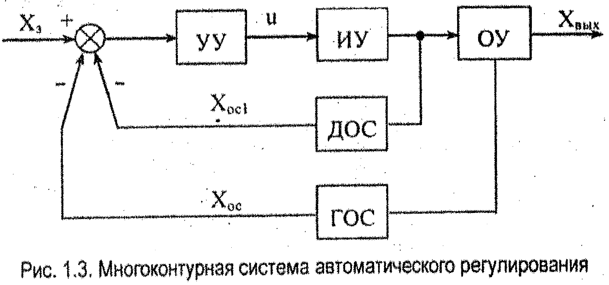
ACS must have at least one feedback, which serves to compare the actual and set values of the controlled variable. Such feedback is called the main one. It connects the output of the system with its input, covering all the main elements. Systems that have one main feedback (GOS) are called single-loop. Some ACS, in addition to the main feedbacks (GOS), the number of which is determined by the number (GOS) of controlled variables, may have several additional (local) ones. Additional feedback (DOS) connects the output of one or more elements of the system. ACS that, in addition to the main one, have one or more additional feedbacks are called multi-loop (Fig. 1.3).
Depending on the nature of the transmitted impact, feedbacks are divided into rigid and flexible. Rigid feedbacks operate both in steady state and in transient modes. Flexible feedbacks operate only in transient modes. The means of implementing hard feedback are various measuring devices - sensors that transmit a signal to the comparison node. The means of implementing flexible feedbacks are differentiation and integration devices.
According to the effect on the system, feedbacks are divided into positive and negative. Positive if the control signal at the input increases with an increase in the output signal, and negative if the control signal at the input decreases with an increase in the output signal.
Disadvantages of disturbance controlled systems can be eliminated by using combined control systems, in which disturbance control is combined with deviation control. In this case, the influence on the control process of the main disturbance is eliminated. In addition, due to the presence of feedback on the controlled value , the effect of minor perturbations is limited. Sometimes these systems are called open-closed. They have a relatively high accuracy of maintaining a given controlled value.
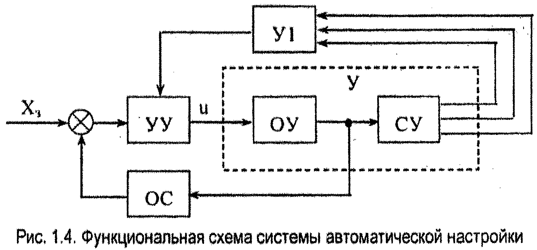
The functional diagram of the control system, which provides the setting and selection of the required control algorithm depending on the change in operating conditions and parameters of the control object, is shown in fig. 1.4.
| Content | 2 | |
| Introduction | 3 | |
| 1. | a common part | |
| 1.1. | Basic concepts | 6 |
| 1.2. | Description of the original automatic control scheme | 9 |
| 1.3. | Development of a functional diagram of the ATS | 13 |
| 2. | Settlement part | |
| 2.1. | Parametric synthesis and analysis of a single-loop ACS | 14 |
| 2.1.1. | Evaluation of the possibility of static control | 15 |
| 2.1.2. | Evaluation of the possibility of astatic control | 20 |
| 2.1.3. | Study of the quality of a single-loop ATS | 22 |
| 3. | Development of a control loop with a given parameter | 25 |
| Conclusion | 27 | |
| Bibliography | 28 |
Introduction
The modern theory of automatic control is the main part of the control theory. The automatic control system consists of an adjustable object and controls that act on the object when one or more adjustable variables change. Under the influence of input signals (control or disturbance), the controlled variables change. The purpose of regulation is to form such laws, under which the output regulated variables would differ little from the required values. The solution of this problem in many cases is complicated by the presence of random perturbations (noise). In this case, it is necessary to choose such a control law in which the control signals would pass through the system with low distortions, and the noise signals would be practically not transmitted.
The theory of automatic control has come a long way in its development. At the initial stage, methods were created for analyzing the stability, quality and accuracy of regulation of continuous linear systems. Then the methods of analysis of discrete and discrete- continuous systems. It can be noted that the methods for calculating continuous systems are based on frequency methods, and the calculation of discrete and discrete-continuous systems is based on z-transform methods.
Currently, methods for the analysis of nonlinear automatic control systems are being developed. Violation of the superposition principle in nonlinear systems, the presence of a number of alternating (depending on the impact) regimes of stable, unstable motions and self-oscillations complicate their analysis. The designer encounters even greater difficulties when calculating extreme and self-adjusting control systems.
Both the theory of automatic control and the theory of control are included in science under the general name "technical cybernetics", which has now received significant development. Technical cybernetics studies the general patterns of complex dynamic control systems for technological and production processes. Technical cybernetics, automatic control and automatic regulation are developing in two main directions: the first is associated with constant progress and improvement in the design of elements and the technology of their manufacture; the second - with the most rational use of these elements or their groups, which is the task of designing systems.
The design of automatic control systems can be carried out in two ways: by the analysis method, when, with a pre-selected system structure (by calculation or modeling), its parameters are determined;
synthesis method, when, according to the requirements, the system is immediately selected
its best structure and parameters. Both of these methods are widely practical use and therefore are fully covered in this book.
Determining the parameters of the system, when its structure and requirements for the entire system as a whole are known, refers to the problem of synthesis. The solution to this problem with a linear control object can be found using, for example, frequency methods, the root locus method, or by studying the trajectories of the roots of the characteristic equation of a closed system. Selection of a corrective device by synthesis in the classroom fractional rational functions complex variable can be done using the graph analytical methods. The same methods make it possible to synthesize corrective devices that suppress self-oscillating and unstable periodic modes in nonlinear systems.
Synthesis methods were further developed on the basis of the principles of maximum and dynamic programming, when the optimal control law from the point of view of a given quality criterion is determined, which provides the upper limit of the quality of the system, which must be strived for when designing it. However, the solution of this problem is practically not always possible due to the complexity of the mathematical description of the physical processes in the system, the impossibility of solving the optimization problem itself and the difficulties in the technical implementation of the found nonlinear control law. It should be noted that the implementation of complex control laws is possible only when a digital computer is included in the system loop. The creation of extreme and self-adjusting systems is also associated with the use of analog or digital computers.
The formation of automatic control systems, as a rule, is performed on the basis of analytical methods of analysis or synthesis. At this stage of designing control systems, based on the accepted assumptions, a mathematical model of the system is compiled and its preliminary structure is selected. Depending on the type of model (linear or non-linear), a calculation method is chosen to determine the parameters that provide the specified indicators of stability, accuracy and quality. After that, the mathematical model is refined and, using the means mathematical modeling determine the dynamic processes in the system. Under the action of various input signals, the frequency characteristics are taken and compared with the calculated ones. Then the stability margins of the system in phase and modulus are finally established and the main quality indicators are found.
Further, setting typical control actions on the model; remove the characteristics of accuracy. On the basis of mathematical modeling, technical requirements for the system equipment are drawn up. A controller is assembled from the manufactured equipment and transferred to semi-natural modeling, in which the control object is collected in the form of a mathematical model.
According to the characteristics obtained as a result of HIL modeling, a decision is made on the suitability of the controller to work with a real object of regulation. The final selection of the controller parameters and its adjustment is carried out in natural conditions during the experimental development of the control system.
The development of the theory of automatic control based on the equations of state and z-transforms, the maximum principle and the dynamic programming method improves the method of designing control systems and allows you to create highly efficient automatic systems for the most various industries National economy. The automatic control systems obtained in this way ensure the high quality of products, reduce their cost and increase labor productivity.
1. General part.
1.1. Basic concepts
System input conversion (control action) into the output signal (adjustable value) determines the law of change of the regulated value. Realization of the desired law is implemented as a result formation control variables, that affect the controlled system. The laws of change of the regulated value in time may be different; mathematically they are described system operator. This operator can implement a proportional dependence of the output signal on the input, a connection in the form of a derivative or an integral, etc. In a more general case, this operator can also be non-linear.
It should be noted that the laws of change of controlled values in machines and units are violated under the influence of external and sometimes internal influences, called disturbances. (or disturbing influences). From the definition of these influences, it can be seen that the automatic control system should reproduce the control action as accurately as possible and respond as little as possible to the disturbing action.
There are three various principle construction of control systems that ensure the implementation of the required law of change in the controlled variable: open-loop, closed-loop, combined-loop regulation (closed-open). The principle of an open cycle is to ensure the required law of change of the controlled variable directly by converting the control action. The principle of a closed cycle is characterized by a comparison of the control action with the actual change in the controlled variable due to the application feedback and comparison element. The error signal resulting from the comparison should not exceed a certain predetermined value. Due to this, the required law of change of the controlled variable is ensured in closed systems. The combined principle consists in the combination of closed and open loops in one system.
Automatic control called the process in which
operations are performed by a system that operates without human intervention in accordance with a predetermined algorithm.
An automatic system with a closed circuit of influence, in which the control (regulatory) action is generated as a result of comparing the true value of the controlled (adjustable) quantity with its given (prescribed) value, is called ASR.
Manufacturing process- a set of interrelated labor and technological processes, during the implementation of which raw materials and semi-finished products are converted into finished products.
Automatic are the devices that control various processes and control them without direct human intervention.
The subject or process to be studied is called object, and all surrounding objects interacting with them - external environment.
System- a set of elements or devices that are in relationships and connections with each other and form a certain integrity (unity).
Control object- a set of technological devices (machines, tools, mechanization) that perform this process from the point of view of management.
Control operation- provides at the right time the beginning, sequence and termination of work operations, allocates the resources necessary for their implementation.
Under management understand the process of organizing such a purposeful impact on the control object, as a result of which the latter goes into the required (purposeful) state.
The parameters of a production process or a process or a process object that must be constantly maintained or changed according to a certain law is called controlled quantity.
The value of the controlled variable, which, according to the task, should be at a given time, is called the given value of the controlled variable (controlled parameter).
A diagram depicting the sequence of processes within a device or system is called structural diagram.
Link- an element included in the ACS in which the input parameter is converted in a certain way into the output parameter (it is schematically depicted as a block, but does not reflect the features of its design).
Information is always associated with a material carrier of some physical quantity. AT technical systems such carriers are called signal carriers(for example, electrical voltages and current, pressure, mechanical movement, etc.), which can be changed in accordance with the transmitted information.
1.2. Description of the original automatic control scheme.
Since the regulated object is an element or link of the ACP, the properties of the ACP depend primarily on the properties of the regulated object. Therefore, in order to create a workable ACP that provides the required quality of regulation, it is necessary, first of all, to know the properties of the regulated object (spastic and dynamic).
The object of regulation of the laboratory stand is an object with distributed parameters, since the controlled value (temperature) is not the same at different points of the object both in the equilibrium state and in the transition mode.
To increase the inertia of the object, which should be ten times greater than that measured in this object by the sensor, a metal cup filled with chips is provided, in which the temperature sensor is located. This allows you to increase the heat volume of the object.
The required temperature (reference) is set by the device at the inlet of the controller-setter (t e).
Disturbance
Rice. 1. Regulatory scheme.
The actual temperature is converted into a signal by the device t f. Denoting the signals at the output of these devices by letters similar to them, we express the actual deviation from the required one in the form of a signal: ∆t = t e - t f; called deviation or mismatch. The controller converts ∆t according to a certain control law and turns on the actuator. In our case, the task of the regulator is the liquidity of deviations ∆t caused by the action of disturbances B, i.e. various loads on control objects (changes in ambient temperature, changes in the position of the gate, etc.).
An error ∆t may also occur due to a change in t e, but since it is a function known in advance, the error can also be calculated in advance and compensated. Such a system is called a program control system or simply ACS.
The stand provides two-position regulation. In this case, it is necessary to open the damper so that the electric heating element is constantly blown by air. The temperature is controlled by switching the heating element on or off by the relay element.
To determine the dynamic properties of the object, a self-recording device is installed in the stand, which registers temperature changes in the object and fixes them on a chart tape.
Any technological unit that is the object of regulation of the OR operates in a steady state if the material and energy balance is fully observed in it. The main parameter characterizing the conditions for the flow of the technological process (in our object it is temperature) remains unchanged in the steady state.
The dependence of the output value on the input value in steady state is called the static characteristic of the OR. Static characteristics can be both linear, with different slope coefficients, and non-linear, while most real objects in general have non-linear ones.
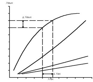
Fig 1.1. Static characteristics of OR.
These characteristics of the OR make it possible to assess the degree of connection between various input and output values of the object.
Static characteristics are determined by calculation or experimentally.
Dynamic characteristic of the regulated object is called the dependence of the output value on the input value in the transient mode.
Since the changes in the output value of RR under various disturbances can occur in different ways, typical external influences are usually used to study the dynamic characteristics of an object.
The temperature ACS acceleration curve (Fig. 1.2.) indicates the dynamic properties of the OR.
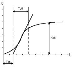
Fig 1.2. Acceleration curve
The figure shows that the object has the ability to gradually stop the deviation of the output value from the initial value and the equilibrium state is restored again, i.e. the object has the self-alignment property. Such objects are called static.
The object has a delay T about, and since It is not significant and will be neglected in what follows.
The time constant of the object T about is the conditional time during which the output value would change from the initial value to a new steady value if this change occurred at a constant and maximum rate for a given transient. The time constant characterizes the inertia of an object, which is understood as its ability to slowly accumulate and consume matter and energy, which becomes possible due to the presence of resistances and capacitances in the OR that prevent their entry and exit.
The transfer coefficient K about OR is a change in the output value of the object during the transition from the initial to the new to the steady state, referred to a single perturbation at the input.
A single perturbation is considered a one percent change in the input value of the object (displacement of the regulatory body).
In this way:
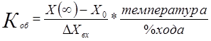
where x o is the value of the output quantity in the initial steady state; X(∞)– too, but for a new steady state; ∆Х in is the magnitude of the introduced perturbation; % stroke of the regulator.
1.3. Development of a functional diagram of the ACS.
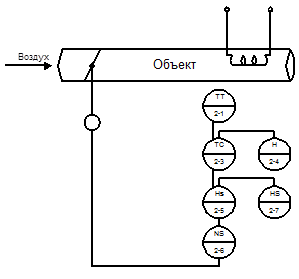
Figure 2. Three-position control loop.
The object of regulation is static in its features with self-alignment with a transfer delay, which contributed to the choice of a proportional-integral controller.
The circuit includes measuring the temperature of the coolant and comparing with the task, the regulator through the HS - manual control unit, turns on the contact "more" or "less" contactless starter NS, which in turn controls the actuator, i.e. air supply to the coolant.
With two-position regulation, the relay element regulates the inclusion of the coolant.
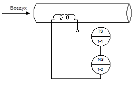
Figure 3. Two-position control loop.
When a certain temperature is reached, the starter turns off the voltage supply to the electric heating element. Measurement and regulation of temperature is carried out by a dynamometric sensor - a temperature relay.
2. Settlement part.
2.1. Parametric synthesis and analysis of single-loop ACS.
The analysis of automatic control systems with elements of electroautomatics is carried out using the algebraic criteria of Gauss and Hurwitz, the Lyapunov criterion, the frequency criteria of Mikhailov, Nyquist - Mikhailov, etc.
When analyzing ACS, stability issues and other qualitative indicators of open and closed ACS are studied, stability margins are found in modulus and phase, astatism of closed systems, error rates for servo systems, etc. are determined.
The main qualitative indicators of systems, which are determined after finding the so-called h-functions, include the following:
1. The time of the transient process t p, after which the controlled value will remain close to the steady value;
2. Steady value of the controlled variable h¥=limh(t)=h y ;
3.Maximum overshoot y=(h max -h y)/h y (here h max is the value of the first maximum);
4. Oscillation frequency w=2p/T (here T is the oscillation period);
5. The number of oscillations of the transient process n;
6.Time to reach the first maximum t max ;
An important indicator of the quality of ACS is their reliability. Qualitative indicators are determined by solving differential equations, which describe already known ACS structures.
Synthesis of ACS consists in finding its structures and parameters that would meet the given quality indicators. Synthesis is a more difficult task than analysis. The main methods used in the synthesis of ACS are analytical, graphic-analytical and machine (with the help of computers).
2.1.1. Evaluation of the possibility of static regulation.
When choosing a controller, it is necessary to know the numerical dynamic information about the object of regulation, i.e. K 0 ; T about; t 0 , which we determine by the acceleration characteristic.
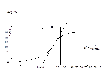
Fig. 4. Acceleration curve of the ACS temperature of the laboratory stand.
The type of regulator is tentatively chosen in relation to t/T about;
Criteria for selecting regulators by type of action.
To study and calculate the structural diagram of the ASR by means of equivalent transformations, it is necessary to reduce it to the simplest standard form of the object-regulator. This is necessary, firstly, in order to determine its transfer functions, and, consequently, the mathematical dependencies that determine the transient processes in the system, and secondly, as a rule, all engineering methods for calculating and determining the settings of the controllers are used for such a standard structures.
So the original block diagram of the temperature ACS according to a typical functional diagram (see drawings) can be represented as shown in the figure.
Where W P (p), W IM (p), W PO (p), W OP (p), W IU (p), are the transfer functions of the controller, actuator, regulatory body, control object and measuring device, respectively.
On the structural diagram, all influences (signals) should be indicated in the Laplace-transformed form.
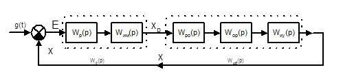
Figure 5. Transformed block diagram of the ACS (t).
All links that determine the dynamic properties of interface nodes (connections, interconnections) of an object with a controller (for example, regulatory bodies, communication lines, measuring devices, sensors, etc.), it is advisable, as a rule, to refer to the object of regulation.
If the controller and the actuator directly implement the control law in the system, then the transfer function of the controller
W P (p) \u003d W y (p) W IM (p)
Static regulation is characterized by the presence of a P-regulator, then
W P (p) \u003d K reg
When optimizing the values, according to experimental data, it is advisable to take K - the coefficient of the regulator to take K = 10
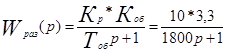
The transfer function of the regulated object, taking into account the links related to the object itself, has the form:
W about (p) \u003d W PO (p) W OP (p) W IU (p)
In the general case, any one-dimensional ACS with the main feedback, by gradually strengthening the links, can be reduced to the simplest form, the transfer function of an open system, which
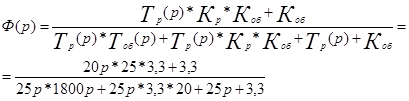
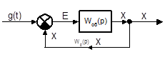 W(p)=W P (p)*W OB (p)
The temperature ACS acceleration curve shows that the object is inertial, static and has a delay, since the delay is insignificant. In further research, they can be neglected. Then the transfer function of the object will look like this:
W about (p) \u003d K about / (T about p + 1)
Transfer function of an open system
W(p)=W P (p)*W OB (p)
 - with static regulation.
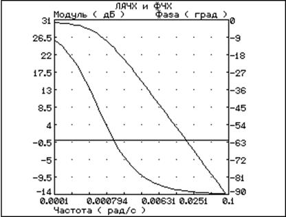
Fig 6. LAFC and LFC for the object.
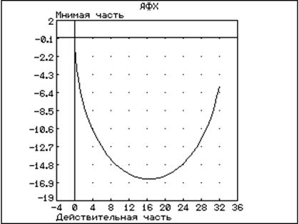
Fig 7. AFC for an object.
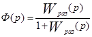
Let's find the transfer function of the closed system:
Because the value of the time constants is determined design features elements of the system, then the adjustment of the control system is carried out only by changing its coefficient K by influencing the transfer coefficient K p of the controller.
To determine the stability of the system, we build the amplitude-frequency, phase-frequency characteristics on a logarithmic scale and build a hodograph using a closed system.
![]()
Fig. 8. LAHCH and LPCH with static regulation.
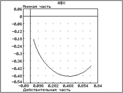
Figure 9. Amplitude-phase characteristic of a closed system.
According to the graphs, we see that with the coefficient of the regulator K p = 10, the stability margin is fulfilled, because at the cutoff frequency wav, the phase is less than 180°, which characterizes the stability of the system under static control, which means that it is possible to use a P-controller for temperature ACS.
2.1.2. Evaluation of the possibility of astatic regulation.
One of the signs of an astatic link (or the system as a whole) is the presence of a complex variable P as a factor in the denominator of the transfer function, i.e. the presence of an integrating component.
Let us consider the possibility of a PI-law for temperature ACS control. To do this, we will build a block diagram in which we will include a PI controller.
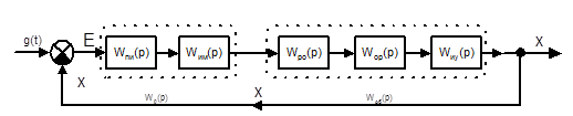
Figure 10. Structural scheme SAR temperature.
The transfer function of the PI controller has the form
W P (p)=K+1/T p; (K=20; Tu=25 sec.)
Let's find the transfer function of an open system
W times (p) \u003d W p (p) W about (p)
Find the transfer function of a closed system
Based on the transfer function of the open system, we build the LFC and LFC, and the function of the closed system, we build the AFC.
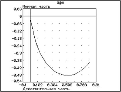
Figure 11. Amplitude-phase characteristic of a closed system.
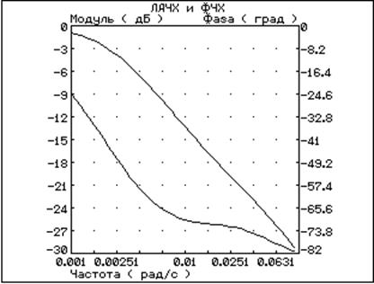
Figure 12. LAFC and LPFC with astatic regulation.
The frequency characteristics show that the system has a margin of stability, both in amplitude and in phase, since at cutoff frequency w avg phase< 180° значит возможно использовать ПИ регулятор для САР температуры.
2.1.3. Investigation of the quality of a single-circuit automatic control system.
To automatic systems regulation imposes requirements not only on its sustainability. For the performance of the system, it is no less necessary that the process of automatic control at certain quality indicators.
The requirements for the quality of the regulatory process in each case can be very diverse, however, of all the quality indicators, several of the most significant can be distinguished, which determine the quality of almost all ACPs with sufficient completeness.
The quality of the system regulation process, as a rule, is evaluated by its transitional function.
The main indicators of quality are: - regulation time t p - is the time during which, starting from the moment the impact on the system is applied, the deviations of the controlled value Dh (t) from its steady-state value h 0 =h (¥) will be less than the pre-set value E It is usually assumed that after the regulation time has elapsed, the deviation of the regulated value from the steady-state value should be no more than E = 5%. Thus, the regulation time determines the duration (speed) of the transient process.
Overshoot s is the maximum deviation Dh max of the controlled variable from the steady value, expressed as a percentage of h 0 =h(¥).
The absolute value of Dh max is determined from the transient curve:
Dh max \u003d h max - h (¥)
Accordingly, the overshoot will be equal to:

The oscillation of the system is characterized by the number of oscillations of the controlled value during the regulation time t p. If during this time the transient process in the system makes the number of oscillations less than the specified one, then it is considered that the system has the required quality of regulation in terms of its oscillation;
Steady error E. The steady value of the controlled variable h 0 at the end of the transient process depends on the astaticism n of the system. AT static systems(n=0) – steady-state error at constant value input action is not equal to 0 and, therefore, the steady value of the controlled variable h 0 will differ from its set value by the value of the steady-state error.
For the channel of the disturbing influence, the error value is determined by the expression
![]()
where x 0 is a constant driving force; K is the system transfer coefficient.
Through the channel of the perturbing influence, the error value according to the expression
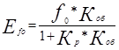
where f 0 is a constant disturbing action; K about - the transfer coefficient of the regulated object; K p - the transfer coefficient of the regulator.
Comparing the transient functions of static and astatic control, we choose the optimal controller for temperature ACS.
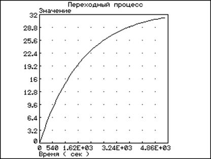
Fig. 13. Transient function of ACS with P-regulator
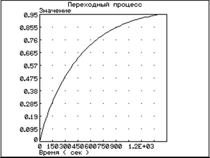
Figure 14. ACS transient function with PI controller
The graphs show that the regulation time with a PI controller is shorter than with a P controller; it means that for temperature ACS it is expedient to use a pulse controller that fulfills the PI-regulation law.
For calculations, the Classic program was used on a computer.
3. Development of a control loop scheme for a given parameter.
The schemes are made in accordance with GOST 2.710-81.
Figure 15. Three-position control loop.
The power supply to the laboratory stand is carried out by the automatic power supply SF1 scheme No. 003E3. In this case, the heating element of the control object is switched on through the opening contact KM 1.1. relay KM 1, and a secondary indicating self-recording device KSU 4. In the 90 ° position of the universal switch SA1, the fan motor. In position -45°, switch SA1, is included in positional regulation, in position +45° - three-position regulation.
With 2-position regulation, the KM1 relay winding is switched on through the opening contact of the TUDE1 sensor. When the set temperature on the sensor is exceeded, its contact opens and opens the KM1.1 contact, turning off the heating element, which is indicated by the HL4 signal lamp.
Three-position regulation is shown in diagram No. 004E2. In automatic mode, the electrical signal from the TSMU thermal converter is sequentially fed first to the input of the KSU4(2) device, terminal 12 and through terminal 11 enters the input 25 of the RBI 1-P control unit.
A current signal proportional to the set temperature value is also supplied to the RBI 1-P clamp 21 input from the RZD setter.
At the output of the regulator, terminals 7 and 9 give the signal “Less” and “More”, respectively, relative to the middle point of the clamp 10. The signal passes through the BRU and the opening contacts SQ1 and SQ2 of the IM actuator, which control the FBR starter, terminals 7 and 9. The FBR turns on IM contacts 1, 2 and 3.
In the manual control mode, the IM is passed by the BRU buttons "More" or "Less".
Conclusion
For the calculated system of the object, the following calculations were made:
Development of a functional diagram of automatic control. The transfer function and structural transformation of the control object scheme are obtained. The frequency characteristics of the control object are constructed. An assessment of the capabilities of a static control object (P-controller), as well as an assessment of the possibility of an astatic control object (PI-controller) was made. A study was made of the quality of a single-loop automatic control system.
The construction of the desired frequency characteristics of the corrected system has been completed. The selection and calculation of the corrective device is carried out. The quality of the adjusted system was assessed.
The development of a control loop scheme for a given parameter has been completed.
Based on the calculations, we can say that the selection of the corrective device was made correctly and meets the quality indicators of the system with the correction made.
Bibliography.
- I.Yu. Topchev "Atlas for CAP Design"
- B.C. Chistyakov "A Brief Guide to Thermal Engineering Measurements"
- N.N. Ivashchenko "Automatic regulation"
4. V.V. Cherenkov "Industrial devices and means of automation"
We advise you to read
, diagnosis, treatment Treatment of urogenital chlamydia") Chlamydia urogenital - description, causes, symptoms (signs), diagnosis, treatment Treatment of urogenital chlamydia
Chlamydia urogenital - description, causes, symptoms (signs), diagnosis, treatment Treatment of urogenital chlamydia The benefits and significance of hydroamino acid threonine for the human body L threonine what
 To wait or not to wait for a guy from the army For what reason can they be commissioned from the army
 Baked apples with cottage cheese Baked apples with cottage cheese

