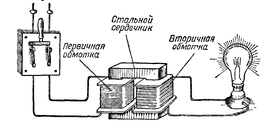
The main purpose of a transformer is to convert current and voltage. And although this device performs quite complex transformations, in itself it has a simple design. This is a core around which several coils of wire are wound. One of them is the input (called the primary winding), the other is the output (secondary). An electrical current is applied to the primary coil where the voltage induces a magnetic field. The latter in the secondary windings forms an alternating current of exactly the same voltage and frequency as in the input winding. If the number of turns in the two coils is different, then the current at the input and output will be different. Everything is quite simple. True, this device often fails, and its defects are not always visible, so many consumers have a question, how to check the transformer with a multimeter or other device?
It should be noted that the multimeter is also useful if you have a transformer with unknown parameters in front of you. So they can also be determined using this device. Therefore, starting to work with him, you must first deal with the windings. To do this, you will have to pull out all the ends of the coils separately and ring them, thereby looking for paired connections. In this case, it is recommended to number the ends, determining which winding they belong to.
The simplest option is four ends, two for each coil. More common are devices that have more than four ends. It may also turn out that some of them “do not ring”, but this does not mean that they have a break. These may be the so-called shielding windings, which are located between the primary and secondary, they are usually connected to the "ground".
That is why it is so important to pay attention to resistance when dialing. In the network primary winding, it is determined by tens or hundreds of ohms. Please note that small transformers have great resistance primary windings. It's all about more turns and a small diameter of copper wire. The resistance of the secondary windings is usually close to zero.
Transformer check
So, with the help of a multimeter, the windings are determined. Now you can go directly to the question of how to check the transformer using the same device. We are talking about defects. There are usually two of them:
- cliff;
- insulation wear, which leads to a short circuit to another winding or to the device case.
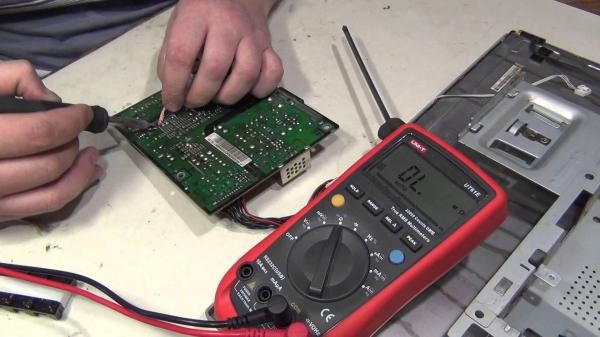
A break is easy to determine, that is, each coil is checked for resistance. The multimeter is set to ohmmeter mode, two ends are connected to the device with probes. And if the display shows the absence of resistance (readings), then this is guaranteed to be a break. Checking with a digital multimeter may be unreliable if a winding with a large number of turns is being tested. The thing is that the more turns, the higher the inductance.
The closure is checked like this:
- One multimeter probe closes to the output end of the winding.
- The second probe is alternately connected to the other ends.
- In the case of a ground fault, the second probe is connected to the transformer case.
There is another common defect - this is the so-called inter-turn circuit. It occurs if the insulation of two adjacent turns wears out. In this case, the resistance remains at the wire, therefore, in the place where there is no insulating varnish, overheating occurs. Usually, the smell of burning is released, blackening of the winding, paper appears, and the fill swells. This defect can also be detected with a multimeter. In this case, you will have to find out from the reference book what resistance the windings of this transformer should have (we will assume that its brand is known). Comparing the actual figure with the reference one, you can say for sure whether there is a flaw or not. If the actual parameter differs from the reference by half or more, then this is a direct confirmation of the interturn short circuit.
Attention! When checking the transformer windings for resistance, it does not matter which probe is connected to which end. In this case, polarity does not play any role.
No-load current measurement
If the transformer, after testing with a multimeter, turned out to be serviceable, then experts recommend checking it for such a parameter as no-load current. Usually, for a serviceable device, it is 10-15% of the nominal value. In this case, the rating refers to the current under load.
For example, a transformer brand TPP-281. Its input voltage is 220 volts, and the no-load current is 0.07-0.1 A, that is, it should not exceed one hundred milliamps. Before checking the transformer for the no-load current parameter, it is necessary measuring device switch to ammeter mode. Please note that when power is applied to the windings, the inrush current can exceed the rated current by several hundred times, so the measuring device is connected to the device under test short-circuited.

After that, it is necessary to open the terminals of the measuring device, while the numbers will be displayed on its display. This is the current without load, that is, idling. Next, the voltage is measured without load on the secondary windings, then under load. Reducing the voltage by 10-15% should lead to current indicators that do not exceed one ampere.
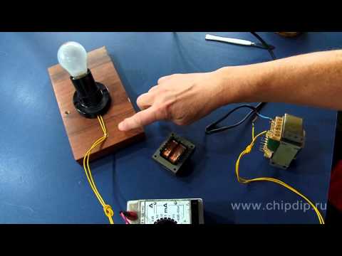
To change the voltage, a rheostat must be connected to the transformer, if there is none, you can connect several light bulbs or a tungsten wire spiral. To increase the load, you must either increase the number of bulbs, or shorten the spiral.
Conclusion on the topic
Before you check the transformer (step-down or step-up) with a multimeter, you need to understand how this device works, how it works, and what nuances must be taken into account when checking. In principle, there is nothing complicated in this process. The main thing is to know how to switch the measuring device itself to ohmmeter mode.
Related posts: 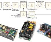
Have a transformer with two windings, four outputs, it costs nothing to ring. The problem is due to a significant difference between real designs. The transformer is equipped with a plurality of secondary winding leads to obtain the desired voltage ratings. The entry side is not easy. Two separate transformers can be wound on one magnetic circuit. How to make a usability assessment? Let's see how to test a transformer.
Checking the transformer by a Chinese tester
Not every transformer is made to be powered by a 220 volt, 50 Hz network. In industry, measurement industry, higher education other devices are used. Observing unsuitable characteristics, using devices in industrial circuits will be a bad idea. Therefore, the first thing we pay attention to is labeling. Conducted in accordance with GOST. The problem appears: an individual document has been issued for each type of transformer.
Symbols of power (GOST 52719-2007) transformers
- Manufacturer's logo. There is such an icon; on the official website of the plant, you can probably get a lot of useful information. The problem is limited to the demise of the enterprise. You understand the liveliness of the issue for a collapsing country. The second turn concerns the search for a short digital marking, we will puzzle the search engine: Yandex, Google. There is a great chance of immediately finding the characteristics, as well as the electrical circuit of the device. Then nothing is easier than ringing the transformer, determining the presence of a breakdown, the integrity of the windings. We remind you that the insulation resistance (on the magnetic circuit, for example) is at least 20 MΩ according to existing standards. Refers to any adjacent, electrically isolated windings. Having bought a Chinese tester, amateurs can do the measurements with their own hands.
- We consider the name of the product to be a key factor. You need to understand: different classes are meant for their own purposes. You can, of course, use the input transformer, forming a galvanic isolation, while understanding the resulting result. In devices, the voltage is usually not standardized separately, the operation is meaningless. The secondary winding of the current transformer is connected to the corresponding coil of the control and measurement device. Stress, if necessary, is evaluated separately. The marking may contain the words "transformer", "autotransformer". Let's get the meaning right away. Help Yandex. For example, an autotransformer is characterized by the absence of galvanic isolation between the primary and secondary windings. In fact, during the movement of electric trains, it is convenient to arrange autotransformers at intervals, to remove the voltage by a typical method. The trajectory of the current movement will significantly reduce losses. The distance between the source and ground (through the rails) is reduced. There are many other types of transformers. The type is determined, we find the GOST of the corresponding class of the device, we move on, equipped with reliable information support. Regarding this class of devices, we find: marking is carried out in accordance with GOST 11677-75. It is different to GOST, according to which the consideration was started, due to a different scope. GOST 11677 is international. Therefore, you need to know: even for one class of products, the tag is not the same.
- The serial number will help you get technical support. We know for sure that specialists who know English live in Taiwan, China, we strongly recommend that you try to contact us if you have any problems. For Soviet products, information is more likely to be useless.
- The type convention will help you understand design features. For example, let's meet TZRL. According to GOST 7746-2001, there are tables (2 and 3) that lead the decoding. As for the first letter, characterizes the word "transformer". Bad luck - the plate is devoid of decoding the letter Z. Give up? We visit Yandex, we soon find: Z means “protective”. Then it’s simple: the letter O according to the table is “reference”, L characterizes the cast type of insulation. We find the climatic modification U2. Decryption is carried out in accordance with GOST 15150, placement category type 2 GOST 15150. Having information on hand, you can find distinctive features transformer. As for the future placement, we undertook to check the transformer for a reason. Surely a warm place has been prepared that meets the specified standards.
- We consider useful information related to regulatory documentation. The standard according to which the transformer is manufactured is indicated by the nameplate. It remains to open the document, decipher the inscription. In each specific case, there may be slight deviations in the designations, a search engine (Yandex, Google) will help you figure it out.
- The date of manufacture is indicated by the soft aluminum plate. The information will be useful to those who wish to contact the manufacturer's technical support service.
- Nameplate provides a drawn wiring diagram winding connections, pin numbers (colors, other symbols). According to the information, nothing is easier than finding transformer faults. Even if the nameplate is half-erased, you can certainly find a plate of a similar device. Then you can redraw, print the necessary information. On specialized forums, amateurs willingly share such information. Time to despair. Finally, we will learn a lot from reference books. Find using Yandex. Look for electronic versions of books, network resources suffer from little accuracy. The search string contains file extensions: djvu, pdf, torrent. Do not worry about copyright, the book is downloaded for review. Seen, removed. You can not transfer the received information, of course. I came across a brochure developed by ABS Electro, which provides the necessary information on products. Inside some devices there are thermal relays, some other elements. Therefore, ringing a transformer is ten times more difficult than an ordinary one. In consumer electronics, there is often a 135 degree Celsius fuse hidden by turns of the primary, secondary windings, a truly complex product will surprise seasoned researchers. By the way, thermal fuses sometimes decorate the magnetic circuit, the tester showed a winding break, look for protective elements.
- The rated frequency Hz may be absent if the network corresponds to the standard (industrial). A high-frequency transformer should not be used instead of a conventional one. There will be completely different resistance of the windings, the characteristics will change. The transformer will not work properly, it will get hotter.
- The characteristics of the operating mode are indicated if the nature of the operation of the transformer is knocked out of the scope of the term "continuous". According to accepted standards, the device can work indefinitely. Otherwise, the operating cycle is given. After a certain period of activity, the transformer will need to rest. Otherwise, it will burn out, the protection will work (relays, fuses), or the winding will fail due to overheating.
- Rated apparent power kVA is specified for significant windings. Good to know: HH means low, HH high voltage. Easy to understand by examining the transformer welding machine. The current of the electrodes is large, the voltage is low. The coils are formed by a thick wire, the resistance is small. Rated total power will allow you to match the source with the consumer. Let's say there is low-voltage equipment, you need to quickly select a transformer. Avoiding racking your brains, you should compare the power: consumption, allowable secondary winding of the transformer. Aspects will become clearer. Max power equipment consumption is lower than the working (nominal) secondary winding of the transformer.
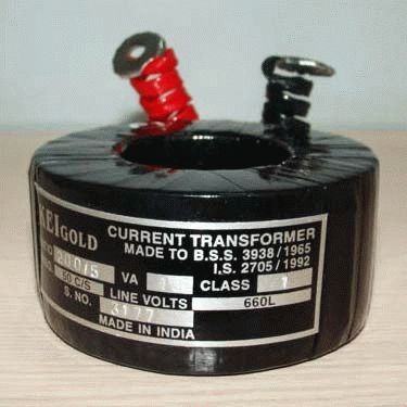
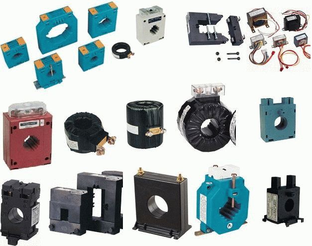
Current transformer nameplate
- The voltage rating of the main secondary winding is a characteristic by which you can understand whether the transformer is working. Enough to secure the absence short circuit, turn on the primary winding in the network. We will measure with a tester (designed for the specified range). Much more reliable than measuring resistance, trying to calculate the gain.
- In voltage stabilizers, transformers with a variable number of turns are more often used. A special slider bypasses the secondary winding, removing the desired voltage. The marking of some transformers contains voltage limits. Of course, it is taken into account by the inspector. By the way, more often in this place lies the malfunction of the transformers. Either closes adjacent turns, or poor contact of the slider. We'll fix the damage we find.
- The rated currents of the windings will sometimes allow you to pick up the components of the network without looking. For example, automatic protection. Many devices provide maximum current load parameters. It is useful to measure the value with an ammeter, you will need to connect the consumer. It is clear that a short circuit of the secondary winding should not be done.
- The short-circuit voltage of the secondary winding is indicated as a percentage of the nominal value. It is clear that, unlike the ideal source of energy studied by teachers of physics lessons, real devices are powerless to give indicators. Therefore, with a sharp increase in current, the voltage drops rapidly. Percentages are relative nominal value. You can calculate the specific value yourself by enlisting the help of the Windows OS calculator. Whether it is worth trying to organize a short circuit with your own hands, we find it difficult to say. Risky: plugs will be knocked out, the transformer is endangered.
We hope that we have talked enough about how to troubleshoot transformers. The main thing is to find the cause, then everyone revolves around his own axis. The simplest (often the only) solution to the problem is to rewind the failed reel. It is made with a wire bought on the market, counting the number of turns is a separate art. It's easier to ask the forum. The answer will surely be:
- link to a specialized computer program;
- share experience;
- will advise.
Please note that the symbols, the list of parameters, are determined by the type of transformer. They will not necessarily be identical to the review of the VashTechnik portal.
How to test a transformer?

The transformer, which translates as "Transformer", has entered our lives and is used everywhere in everyday life and industry. That is why it is necessary to be able to check the transformer for operability and serviceability in order to prevent breakage in the event of a failure. After all, the transformer is not so cheap. However, not every person knows how to check the current transformer on their own and often prefers to take it to the master, although the matter is not at all difficult.
Let's take a closer look at how you can check the transformer yourself.
How to test a transformer with a multimeter
The transformer works on a simple principle. In one of its circuits, a magnetic field is created due to the alternating current, and in the second circuit, an electric current is created due to the magnetic field. This allows the two currents to be isolated inside the transformer. To test the transformer, you must:
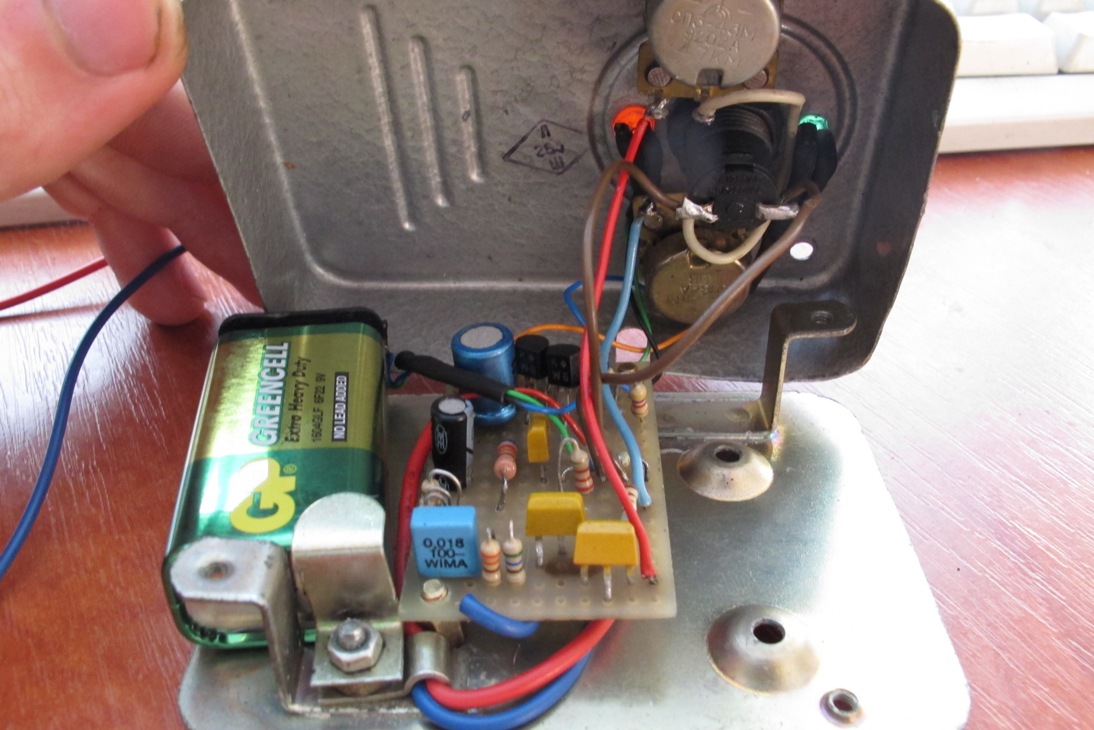
- Find out if the transformer is damaged externally. Carefully inspect the transformer enclosure for dents, cracks, holes, or other damage. Often the transformer deteriorates from overheating. Perhaps you will see traces of melting or swelling on the case, then it does not make sense to look further at the transformer and it is better to take it in for repair.
- Examine the transformer windings. There must be clearly printed labels. It does not hurt to have a transformer diagram with you, where you can see how it is connected and other details. The scheme should always be present in documents or, in extreme cases, on the developer's web page.
- Find also the input and output of the transformer. The voltage of the winding that creates the magnetic field must be marked on it and in the documents on the diagram. It should also be noted on the second winding, where current and voltage are generated.
- Find the filtering at the output where the power is transformed from variable to constant. Diodes and capacitors must be connected to the secondary winding, which perform filtering. They are indicated on the diagram, but not on the transformer.
- Prepare a multimeter to measure the mains voltage measurement. If the panel cover prevents access to the network, then remove it for the duration of the test. You can always buy a multimeter at the store.
- Connect the input circuit to the source. Use the multimeter in mode alternating current and measure the primary winding voltage. If the voltage drops below 80% of the expected value, then the primary winding is likely to fail. Then just disconnect the primary winding and check the voltage. If it rises, then the winding is faulty. If it does not rise, then the malfunction is in the primary input circuit.
- Also measure the output voltage. If there is filtration, then the measurement is carried out in the mode direct current. If not, then in AC mode. If the voltage is incorrect, then it is necessary to check the entire unit in turn. If all parts are in order, then the transformer itself is faulty.
You can often hear a buzzing or hissing sound from the transformer. This means that the transformer is about to burn out and it must be urgently turned off and sent for repair.
In addition, often the windings have different ground potentials, which affects the voltage calculation.
AT modern technology transformers are used quite often. These devices are used to increase or decrease the parameters of a variable electric current. The transformer consists of input and several (or at least one) output windings on a magnetic core. These are its main components. It happens that the device fails and it becomes necessary to repair or replace it. To determine whether the transformer is working, you can use a home multimeter on your own. So, how to check the transformer with a multimeter?
Fundamentals and principle of operation
The transformer itself belongs to elementary devices, and the principle of its operation is based on the two-way conversion of the excited magnetic field. Tellingly, a magnetic field can only be induced using alternating current. If you have to work with a constant, you must first convert it.
The primary winding is wound on the core of the device, to which the external winding is supplied. AC voltage with certain characteristics. It is followed by it or several secondary windings, in which an alternating voltage is induced. The transmission coefficient depends on the difference in the number of turns and the properties of the core.
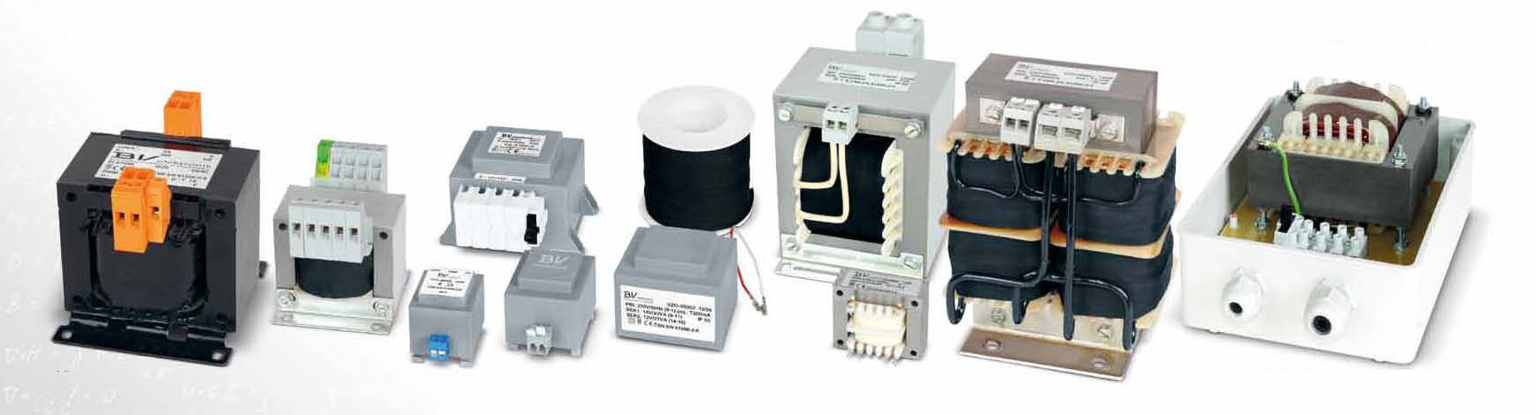
Varieties
There are many types of transformers on the market today. Depending on the design chosen by the manufacturer, a variety of materials can be used. As for the shape, it is chosen solely from the convenience of placing the device in the appliance case. The design power is only affected by the configuration and material of the core. At the same time, the direction of the turns does not affect anything - the windings are wound both towards and away from each other. The only exception is the identical choice of direction if multiple secondary windings are used.
To test such a device, a conventional multimeter is sufficient, which will be used as a current transformer tester. No special devices are required.
Checking procedure
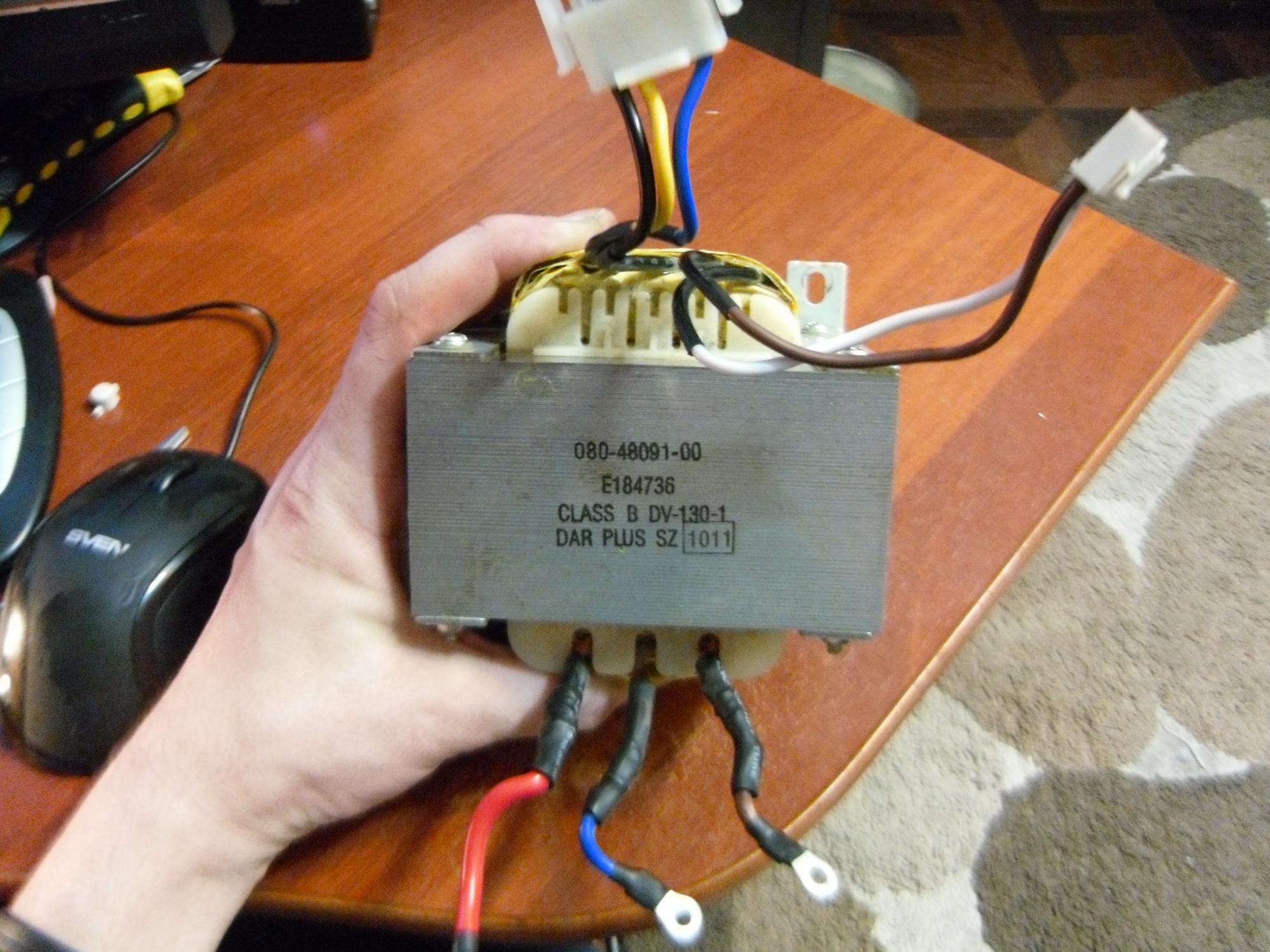
The transformer test begins with the definition of the windings. This can be done by marking on the device. The pin numbers should be indicated, as well as their type designations, which allows you to establish more information from the directories. In some cases, there are even explanatory drawings. If the transformer is installed in some kind of electronic device, then the electronic circuit diagram of this device, as well as a detailed specification, will be able to clarify the situation.
So, when all the conclusions are determined, the tester's turn comes. With it, you can install the two most common malfunctions - a short circuit (to the case or an adjacent winding) and a winding break. In the latter case, in the ohmmeter mode (resistance measurement), all windings call back in turn. If any of the measurements shows one, that is, infinite resistance, then there is a break.
There is an important nuance here. It is better to check on an analog device, since a digital one can give distorted readings due to high induction, which is especially true for windings with a large number of turns.
When a short circuit to the case is being checked, one of the probes is connected to the winding terminal, while the second leads to the conclusions of all other windings and the case itself. To check the latter, you will first need to clean the place of contact from varnish and paint.
Interturn Fault Definition
Another common transformer failure is interturn short circuit. It is almost impossible to check a pulse transformer for such a malfunction with only a multimeter. However, if you involve the sense of smell, attentiveness and sharp vision, the problem may well be solved.
A bit of theory. The wire on the transformer is insulated exclusively with its own varnish coating. If there is an insulation breakdown, the resistance between adjacent turns remains, as a result of which the contact point heats up. That is why the first step is to carefully inspect the device for the appearance of streaks, blackening, burnt paper, swelling and burning smell.
Next, we try to determine the type of transformer. As soon as this is obtained, according to specialized reference books, you can see the resistance of its windings. Next, we switch the tester to the megohmmeter mode and begin to measure the insulation resistance of the windings. In this case, the pulse transformer tester is a regular multimeter.
Each measurement should be compared with that specified in the handbook. If there is a discrepancy of more than 50%, then the winding is faulty.
If the resistance of the windings is not indicated for one reason or another, other data must be given in the reference book: the type and cross section of the wire, as well as the number of turns. With their help, you can calculate the desired indicator yourself.
Checking household step-down devices
It should be noted the moment of checking classic step-down transformers with a tester-multimeter. You can find them in almost all power supplies that lower the input voltage from 220 volts to the output voltage of 5-30 volts.
The first step is to check the primary winding, which is supplied with a voltage of 220 volts. Signs of a primary winding failure:
- the slightest visibility of smoke;
- the smell of burning;
- crack.
In this case, you should immediately stop the experiment.
If everything is fine, you can proceed to the measurement on the secondary windings. You can only touch them with the contacts of the tester (probes). If the results obtained are less than the control ones by at least 20%, then the winding is faulty.
Unfortunately, it is possible to test such a current block only in cases where there is a completely similar and guaranteed working block, since it is from it that the control data will be collected. It should also be remembered that when working with indicators of the order of 10 ohms, some testers may distort the results.
No-load current measurement
If all tests have shown that the transformer is fully functional, it will not be superfluous to conduct another diagnosis - for the current of the idle transformer. Most often, it is equal to 0.1-0.15 of the nominal value, that is, the current under load.
To carry out the test, the measuring device is switched to the ammeter mode. Important point! The multimeter should be connected short-circuited to the transformer under test.
This is important because during the supply of electricity to the transformer winding, the current strength increases up to several hundred times in comparison with the nominal one. After that, the tester probes open, and the indicators are displayed on the screen. It is they who display the value of the current without load, the no-load current. In a similar way, the indicators are measured on the secondary windings.
To measure the voltage, a rheostat is most often connected to the transformer. If it is not at hand, a tungsten spiral or a row of light bulbs can be used.
To increase the load, increase the number of light bulbs or reduce the number of turns of the spiral.
As you can see, no special tester is even required for verification. A normal multimeter will do. It is highly desirable to have at least an approximate understanding of the principles of operation and the design of transformers, but for a successful measurement, it is enough just to be able to switch the device to ohmmeter mode.
Often you need to familiarize yourself in advance with the question of how to test the transformer. After all, if it fails or becomes unstable, it will be difficult to look for the cause of equipment failure. This simple electrical device can be diagnosed with a conventional multimeter. Let's see how to do it.
What is the equipment?
How to check the transformer if we do not know its design? Consider the principle of operation and varieties of simple equipment. Coils of copper wire of a certain section are applied to the magnetic core so that there are leads for the supply winding and the secondary.
The transfer of energy to the secondary winding is carried out in a non-contact way. Here it becomes almost clear how to check the transformer. Similarly, the usual inductance is called with an ohmmeter. The turns form a resistance that can be measured. However, this method is applicable when the target value is known. After all, the resistance can change up or down as a result of heating. This is called interturn short circuit.
Such a device will no longer produce a reference voltage and current. The ohmmeter will only show an open circuit or a complete short circuit. For additional diagnostics, a short circuit test to the case is used with the same ohmmeter. How to test a transformer without knowing the winding leads?
This is determined by the thickness of the outgoing wires. If the transformer is step-down, then the lead wires will be thicker than the lead wires. And, accordingly, on the contrary: the booster wires are thicker. If two windings are output, then the thickness may be the same, this should be remembered. Most the right way look at the label and find specifications equipment.
Kinds
Transformers are divided into the following groups:
- Decreasing and raising.
- Power often serve to reduce the supply voltage.
- Current transformers for supplying a constant current to the consumer and holding it in a given range.
- Single and multi-phase.
- Welding purpose.
- Pulse.
Depending on the purpose of the equipment, the principle of approach to the question of how to check the transformer windings also changes. A multimeter can only ring small devices. Power machines already require a different approach to troubleshooting.
Call method
The ohmmeter diagnostic method will help with the question of how to check the power transformer. The resistance between the terminals of one winding begins to ring. This establishes the integrity of the conductor. Before this, the body is inspected for the absence of carbon deposits, sagging as a result of equipment heating. 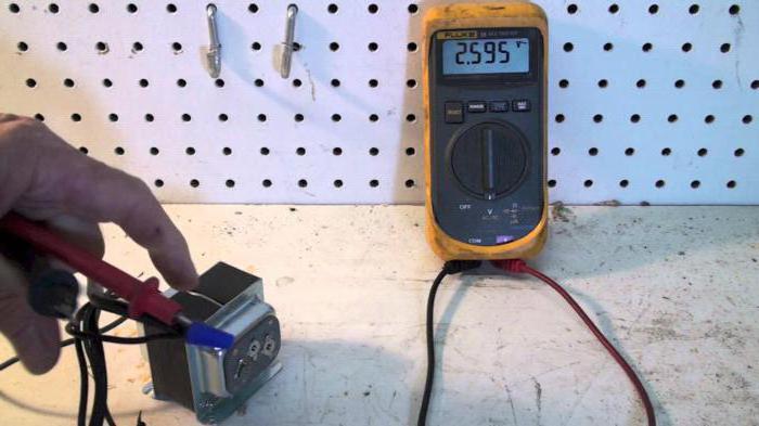
Next, the current values \u200b\u200bare measured in Ohms and compared with the passport ones. If there are none, then additional diagnostics under voltage will be required. It is recommended to ring each output relative to the metal case of the device, where the ground is connected.
Before taking measurements, disconnect all ends of the transformer. It is also recommended to disconnect them from the circuit for your own safety. They also check for electronic circuit, which is often present in modern food models. It should also be soldered before testing.
Infinite resistance speaks of a whole isolation. Values of several kilo-ohms already raise suspicions about a breakdown on the case. It can also be due to accumulated dirt, dust or moisture in the air gaps of the device.
Under voltage
Energized tests are performed when the question is how to test a transformer for turn-to-turn faults. If we know the magnitude of the supply voltage of the device for which the transformer is intended, then measure the idle value with a voltmeter. That is, the output wires are in the air. 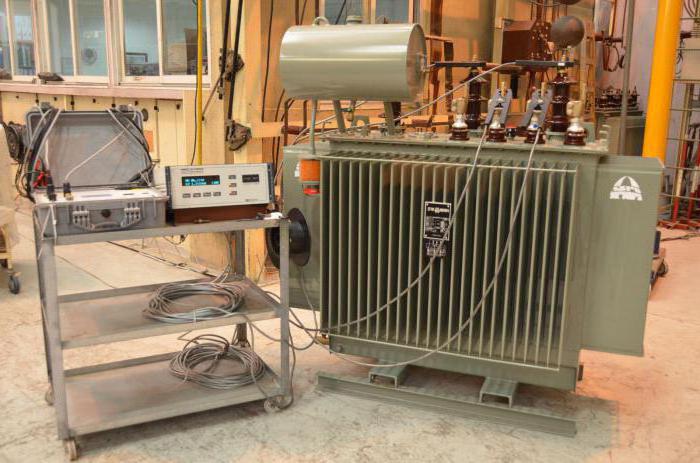
If the voltage value differs from the nominal value, then conclusions are drawn about the interturn circuit in the windings. If crackling, sparking is heard during operation of the device, then it is better to turn off such a transformer immediately. He is defective. There are permissible deviations in measurements:
- For voltage, the values may differ by 20%.
- For resistance, the norm is a spread of values \u200b\u200bin 50% of the passport ones.
Measurement with an ammeter
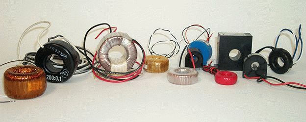
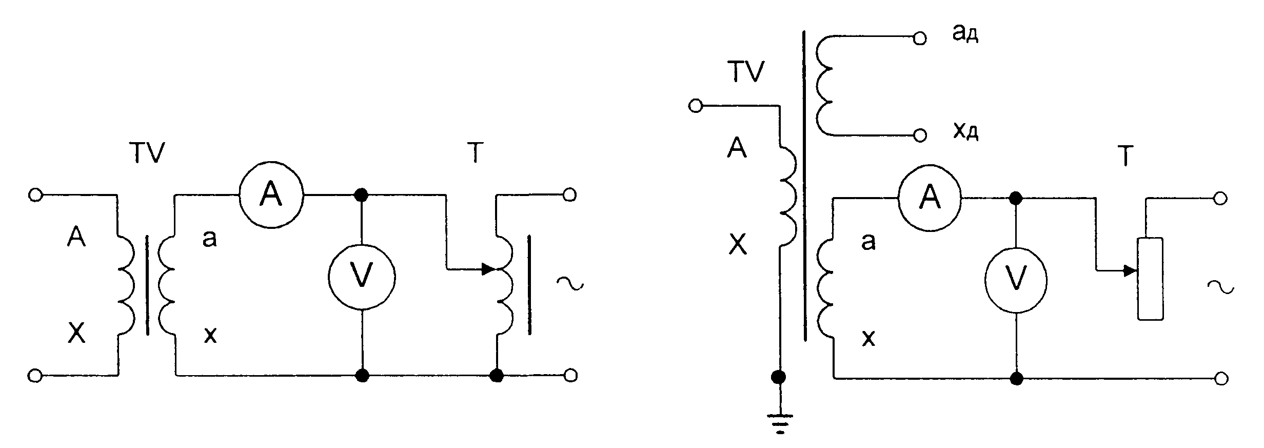
Let's figure out how to check the current transformer. It is included in the chain: regular or actually made. It is important that the current value is not less than the nominal value. Measurements with an ammeter are carried out in the primary circuit and in the secondary. 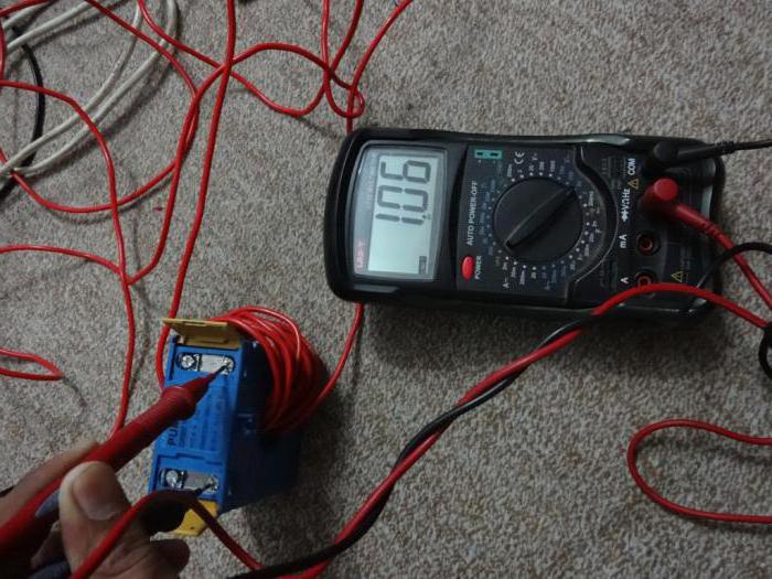
The current in the primary circuit is compared with the secondary readings. More precisely, the first values are divided by those measured in the secondary winding. The transformation ratio should be taken from the reference book and compared with the calculations obtained. The results should be the same.
The current transformer must not be measured at no load. In this case, too high voltage may form on the secondary winding, which can damage the insulation. You should also observe the polarity of the connection, which will affect the operation of the entire connected circuit.
Typical malfunctions
Before checking the microwave transformer, we will give frequent types of breakdowns that can be fixed without a multimeter. Often, power supplies fail due to a short circuit. It is established by inspecting circuit boards, connectors, connections. Less often, mechanical damage to the transformer case and its core occurs. 
Mechanical wear of the connections of the transformer leads occurs on moving machines. Large supply windings require constant cooling. In its absence, overheating and melting of the insulation is possible.
TDKS
Let's figure out how to check a pulse transformer. An ohmmeter can only establish the integrity of the windings. The operability of the device is established when connected to a circuit where a capacitor, a load and a sound generator are involved. 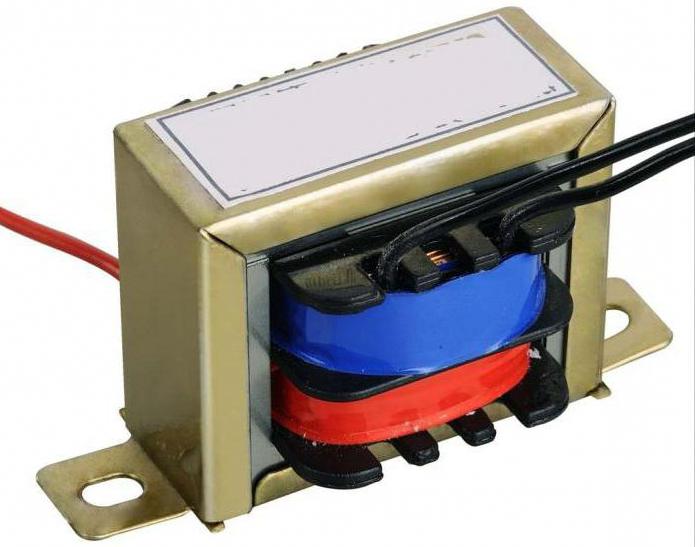
A pulse signal is sent to the primary winding in the range from 20 to 100 kHz. On the secondary winding, measurements are made with an oscilloscope. Establish the presence of pulse distortion. If they are absent, draw conclusions about a serviceable device.
Oscillogram distortions indicate damaged windings. It is not recommended to repair such devices yourself. They are set up in the laboratory. There are other schemes for checking pulse transformers, where the presence of resonance on the windings is examined. Its absence indicates a faulty device.
You can also compare the shape of the pulses applied to the primary winding and exited from the secondary. The shape deviation also indicates a transformer malfunction.
Multiple windings
For resistance measurements, release the ends from electrical connections. Choose any output and measure all resistances relative to the rest. It is recommended to write down the values and mark the tested ends. 
So we can determine the type of connection of the windings: with middle conclusions, without them, with a common connection point. More often found with a separate connection of the windings. Measurement can be done with only one of all the wires.
If available common point, then we measure the resistance between all available conductors. Two windings with a middle terminal will only make sense between the three wires. Several conclusions are found in transformers designed to work in several networks with a nominal value of 110 or 220 Volts.
Diagnostic nuances
The hum during transformer operation is normal if these are specific devices. Only sparking and crackling indicate a malfunction. Often, the heating of the windings is normal work transformer. This is most often seen with step-down devices.
Resonance can be created when the transformer case vibrates. Then you just need to fix it with insulating material. The operation of the windings changes significantly with loose or dirty contacts. Most of the problems are solved by cleaning the metal to a shine and a new close-fitting of the conclusions.
Temperature must be taken into account when measuring voltage and current environment, magnitude and nature of the load. Supply voltage control is also required. Checking the frequency connection is mandatory. Asian and American appliances are rated at 60 Hz, resulting in lower output values.
Improper connection of the transformer may lead to a malfunction of the device. Never connect to windings constant pressure. The coils will melt quickly otherwise. Accuracy in measurements and competent connection will help not only to find the cause of the breakdown, but also, possibly, to eliminate it in a painless way.
We advise you to read
 Psychological characteristics of children in adolescence
 Transferring a child to another school - the procedure and necessary documents Whether to transfer a child to another school
, diagnosis, treatment Treatment of urogenital chlamydia") Chlamydia urogenital - description, causes, symptoms (signs), diagnosis, treatment Treatment of urogenital chlamydia
Chlamydia urogenital - description, causes, symptoms (signs), diagnosis, treatment Treatment of urogenital chlamydia The benefits and significance of hydroamino acid threonine for the human body L threonine what

