Circuit breakers are devices whose task is to protect electrical line from damage due to high current. It can be both short-circuit overcurrents, and simply a powerful electron flow that passes through the cable for a sufficiently long time and causes it to overheat with further melting of the insulation. The circuit breaker in this case prevents negative consequences by turning off the current supply to the circuit. In the future, when the situation returns to normal, the device can be turned on again manually.
Circuit breaker functions
Protective devices are designed to perform the following main tasks:
- Switching of the electrical circuit (the ability to turn off the protected area in the event of a power failure).
- De-energization of the entrusted circuit when short-circuit currents occur in it.
- Protection of the line against overloads when an excessive current passes through the device (this happens when the total power of the devices exceeds the maximum allowable).
In short, AVs simultaneously carry out a protective and control function.

Main types of switches
There are three main types of AB, which differ from each other in design and are designed to work with loads of different sizes:
- Modular. It got its name because of the standard width, a multiple of 1.75 cm. It is designed for small currents and is installed in household power supply networks, for a house or apartment. As a rule, this is a single-pole machine or a two-pole one.
- Cast. It is called so because of the cast body. It can withstand up to 1000 Amps and is used mainly in industrial networks.
- Air. Designed to work with currents up to 6300 Amperes. Most often this is a three-pole machine, but now devices of this type are being produced with four poles.
The single-phase circuit breaker is a circuit breaker, which is most common in household networks. It comes in 1 and 2 poles. In the first case, only the phase conductor is connected to the device, and in the second case, the zero conductor is also connected.
In addition to the listed types, there are also devices protective shutdown, denoted by the abbreviation RCD, and differential automata.

The former cannot be considered full-fledged ABs, their task is not to protect the circuit and the devices included in it, but to prevent electric shock when a person touches an open area. The differential circuit breaker is a combination of AB and RCD in one device.
How are circuit breakers arranged?
Consider in detail the device of the circuit breaker. The body of the machine is made of dielectric material. It consists of two parts, which are connected by rivets. If it is necessary to disassemble the body part, the rivets are drilled out, and access to the internal elements of the circuit breaker is opened. These include:
- Screw terminals.
- Flexible conductors.
- Control handle.
- Movable and fixed contact.
- Electromagnetic release, which is a solenoid with a core.
- Thermal release, which includes a bimetallic plate and an adjusting screw.
- Gas outlet.
On the rear side, the automatic protective fuse is equipped with a special clamp with which it is mounted on a DIN rail.

The latter is a metal rail with a width of 3.5 cm, on which modular devices are attached, as well as some types electric meters. To connect the machine to the rail, the case protective device should be led by its upper part, then snap the latch by pressing on the lower part of the device. You can remove the circuit breaker from the DIN rail by prying the latch from the bottom.
The lock of the modular switch can be very tight. To attach such a device to a DIN rail, you must first pick up the latch from below and bring the protective device into place of the fastener, and then release the locking element.
You can make it easier - when you snap the latch, press firmly on its lower part with a screwdriver.
It is clear why you need a circuit breaker in the video:
The principle of operation of the circuit breaker
Now let's figure out how the network protector works. It is connected by lifting up the control handle. To disconnect the AB from the network, the lever is lowered down.
When the circuit breaker is operating in normal mode, then the electric current with the control handle raised up is supplied to the device through the power cable connected to the upper terminal. The flow of electrons goes to the fixed contact, and from it to the moving one.

Then, through a flexible conductor, the current flows to the solenoid of the electromagnetic release. From it, along the second flexible conductor, electricity goes to the bimetallic plate included in the thermal release. After passing through the plate, the flow of electrons through the bottom terminal goes into the connected network.
Features of the thermal release
If the current of the circuit in which the circuit breaker is installed exceeds the rating of the device, an overload occurs. The flow of high-power electrons, passing through the bimetallic plate, has a thermal effect on it, making it softer and forcing it to bend towards the disconnecting element. When the latter comes into contact with the plate, the machine is triggered, and the current supply to the circuit stops. Thus, thermal protection helps to prevent excessive heating of the conductor, which can lead to melting of the insulating layer and failure of the wiring.
The heating of the bimetallic plate to such an extent that it bends and causes the AB to operate occurs over a certain time. It depends on how much the current exceeds the nominal value of the machine, and can take both a few seconds and an hour.

The operation of the thermal release occurs when the circuit current exceeds the nominal value of the machine by at least 13%. After the bimetallic plate has cooled down and the value of the current current has normalized, the protective device can be turned on again.
There is another parameter that can affect the operation of the AB under the influence of a thermal release - this is the temperature environment.
If the air in the room where the machine is installed is at a high temperature, the plate will heat up to the tripping limit faster than usual and may trip even with a slight increase in current. Conversely, if the house is cold, the plate will heat up more slowly, and the time before the circuit will turn off will increase.
The operation of the thermal release, as was said, requires a certain time during which the circuit current can return to normal. Then the overload will disappear and the device will not turn off. If the magnitude of the electric current does not decrease, the machine de-energizes the circuit, preventing the melting of the insulating layer and preventing the cable from igniting.
The cause of overload is most often the inclusion in the circuit of devices whose total power exceeds the calculated one for a particular line.

Nuances of electromagnetic protection
The electromagnetic release is designed to protect the network from short circuits and, according to the principle of operation, differs from the thermal one. Under the action of short-circuit supercurrents, a powerful magnetic field arises in the solenoid. It moves aside the coil core, which opens the power contacts of the protective device, acting on the release mechanism. The power supply to the line is interrupted, thereby eliminating the risk of fire in the wiring, as well as the destruction of the closing installation and the circuit breaker.
Since in the event of a short circuit in the circuit there is an instantaneous increase in current to a value that can lead to serious consequences in a short time, the operation of the machine under the influence of an electromagnetic release occurs in hundredths of a second. True, in this case, the current should exceed the rating of AB by 3 or more times.
Clearly about circuit breakers in the video:
When the contacts of the circuit through which the electric current flows open, an electric arc occurs between them, the power of which is directly proportional to the magnitude of the mains current. It has a destructive effect on the contacts, therefore, to protect them, the device includes an arc chute, which is a set of plates installed parallel to each other.

Upon contact with the plates, the arc is crushed, as a result of which its temperature decreases and attenuation occurs. The gases that have arisen during the appearance of an arc are removed from the body part of the protective device through a special hole.
Conclusion
In this article, we talked about what circuit breakers are, what these devices are and on what principle they work. Finally, we say that circuit breakers are not intended to be installed in a network as ordinary switches. Such use will quickly lead to the destruction of the contacts of the apparatus.
The circuit breaker (automatic) is used for infrequent switching on and off of electrical circuits and protection of electrical installations from overload and short circuits, as well as unacceptable voltage drops.
Compared to a circuit breaker, it provides more effective protection, especially in three-phase circuits, since in the event of a short circuit, for example, all phases of the network are switched off. Fuses in this case, as a rule, turn off one or two phases, which creates an open-phase mode, which is also an emergency.

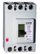
(Fig. 1) consists of the following elements: housing, arc chutes, control mechanism, switching device, releases.
Rice. 1. Circuit breaker, BA 04-36 series (switch device): 1-base, 2-arc chamber, 3, 4-spark arresting plates, 5-cover, 6-plates. 7-link, 8-link, 9-handle, 10-support lever, 11-latch, 12-breaking rail, 13-thermobimetallic plate, 14-electromagnetic release, flexible conductor, 16-current conductor, 17-contact holder, 18-contacts mobile
 To turn on the circuit breaker, which is in the uncoupled position (“Disconnected automatically”), the mechanism must be cocked by moving the handle 9 of the circuit breaker in the direction of the sign “O” until it stops. In this case, the lever 10 engages with the latch 11, and the latch engages with the tripping rail 12. Subsequent switching on is carried out by moving the handle 9 in the direction of the sign “1” until it stops. The failure of the contacts and the contact compression when turned on is ensured by the displacement of the movable contacts 18 relative to the contact holder 17.
Automatic shutdown of the machine occurs when the trip rail 12 is turned by any release, regardless of the position of the handle 9 of the switch. In this case, the handle occupies an intermediate position between the signs "O" and "1", indicating that the circuit breaker is turned off automatically. Arc chutes 2 are installed in each pole of the circuit breaker and are deion gratings consisting of a number of steel plates 6.
Spark arresters containing spark arresting plates 3 and 4 are fixed in the cover 5 of the switch in front of the gas outlet holes in each pole of the circuit breaker. If in the protected circuit, at least one pole, the current reaches a value equal to or greater than the current setting value, the corresponding release is activated and the circuit breaker disconnects the protected circuit, regardless of whether the handle is held in the on position or not. An electromagnetic overcurrent release 14 is installed in each pole of the switch. The release performs the function of instantaneous protection against.
Arcing devices necessary in switching high currents, since the current that occurs when the current breaks causes the contacts to burn. In circuit breakers, arc chutes with deionic arc quenching are used. During deionic extinguishing of the arc (Fig. 2.), above the contacts 1, placed inside the arc chute 2, there is a lattice of steel plates 3. When the contacts open, the arc formed between them is blown upward by the air flow, enters the zone of the metal lattice and is quickly extinguished.
Rice. 2. The device of the arc chute of the circuit breaker: 1 - contacts, 2 - body of the arc chute, 3 - plates.
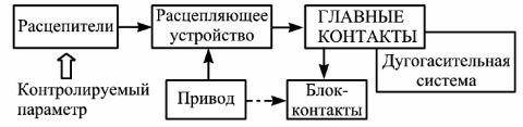
The scheme and main elements of the circuit breaker are shown in Figure 3.
Rice. 3. Automatic circuit breaker device: 1 - maximum release, minimum release, shunt release, 4 - mechanical connection with the release, 5 - manual closing handle, 6 - electromagnetic drive, 7.8 - levers of the free trip mechanism, 9 - opening spring, 10 - arc chute, 11 - fixed contact, 12 - moving contact, 13 - protected circuit, 14 - flexible connection, 15 - contact lever, 16 - thermal release, 17 - additional resistance, 18 - heater.

control mechanism is designed to provide manual switching on and off of the device using buttons or a handle.
Circuit breaker switching device consists of moving and fixed contacts (power and auxiliary). A pair of contacts (movable and fixed) form the pole of the circuit breaker, the number of poles varies from 1 to 4. Each pole is completed with a separate one.
The mechanism that turns off the circuit breaker during emergency conditions is called release. There are the following types of breakers:
Electromagnetic maximum current (to protect electrical installations from short circuit currents),
Thermal (for overload protection),
Combined, having electromagnetic and thermal elements,
Undervoltage (to protect against unacceptable voltage reduction),
Independent (for remote control circuit breaker)
Special (for the implementation of complex protection algorithms).

Electromagnetic release circuit breaker is a small coil with a winding of copper insulated wire and core. The winding is connected to the circuit in series with the contacts, that is, the load current passes through it.
In the event of a short circuit, the current in the circuit increases sharply, as a result, the magnetic field created by the coil causes the core to move (pull into or out of the coil). When moving, the core acts on the tripping mechanism, which causes the opening of the power contacts of the circuit breaker. There are circuit breakers with semiconductor releases that respond to maximum current.
Thermal release automatic switch is made of two metals with different coefficients of linear expansion, rigidly interconnected. The plate is not an alloy of metals, their connection is usually made by pressing. The bimetallic plate is connected to the electrical circuit in series with the load and heated by electric current.
As a result of heating, the plate bends towards the metal with a lower coefficient of linear expansion. In the event of an overload, that is, with a small (several times) increase in the current in the circuit compared to the nominal one, the bimetallic plate, bending, causes the circuit breaker to turn off.
The operating time of the thermal release of the circuit breaker depends not only on the magnitude of the current, but also on the ambient temperature, therefore, in a number of designs, temperature compensation is provided, which ensures that the operating time is adjusted in accordance with the air temperature.
Shunt undervoltage release by design, they are similar to electromagnetic ones and differ from it in terms of operation. In particular, the independent release ensures that the machine is switched off when voltage is applied to the release, regardless of the presence of emergency modes.
These releases are optional and may not be included in the design of the circuit breaker. There are also circuit breakers without any releases, in which case they are named in switch-disconnectors.
Currently, automatic switches of types, AE10, AE20, AE20M, VA04-36, VA-47, VA-51, VA-201, VA88, etc. are common. Automatic switches AP50B are produced for rated currents up to 63A, AE20, AE20M - up to 160A , VA-47 and VA-201 - up to 100A, VA04-36 - up to 400A, VA88 - up to 1600A.
Surely many of us wondered why circuit breakers so quickly replaced obsolete fuses from electrical circuits? The activity of their implementation is justified by a number of very convincing arguments, among which is the opportunity to buy this type of protection, which ideally corresponds to the time-current data of specific types of electrical equipment.
Doubt what kind of machine you need and do not know how to choose it correctly? We will help you find the right solution - the article discusses the classification of these devices. As well as important characteristics that you should pay close attention to when choosing a circuit breaker.
To make it easier for you to deal with the machines, the material of the article is supplemented with visual photos and useful video recommendations from experts.
The machine almost instantly turns off the line entrusted to it, which eliminates damage to the wiring and equipment powered by the network. After the shutdown has been completed, the branch can be immediately restarted without replacing the safety device.

When a short circuit is registered by a short circuit machine, the electromagnetic coil is switched off (situation A). When exceeding rated currents the network is opened by a bimetallic plate (situation B)
The work of the circuit breaker is to protect the wiring (and not equipment and users) from short circuit and from insulation melting when currents exceed the rated values.
By number of poles
This characteristic indicates the maximum possible number of wires that can be connected to the AV to protect the network.
They are switched off when an emergency occurs (when the permissible current values are exceeded or the level of the time-current curve is exceeded).
This characteristic indicates the maximum possible number of wires that can be connected to the AV to protect the network. They are switched off when an emergency occurs (when the permissible current values are exceeded or the level of the time-current curve is exceeded).
Image Gallery


Features of single-pole machines
The single-pole type switch is the simplest modification of the machine. It is designed to protect individual circuits, as well as single-phase, two-phase, three-phase electrical wiring. It is possible to connect 2 wires to the design of the switch - a power wire and an outgoing wire.
The functions of a device of this class include only the protection of the wire from fire. The wiring neutral itself is placed on the zero bus, thereby bypassing the machine, and the ground wire is connected separately to the ground bus.

The connection of a single-pole AB is made with a single-core wire, but sometimes two-core cables are used. Connect the power supply from the top of the machine, and the protected line - from the bottom, which simplifies installation. Installation takes place on an 18 mm din rail
A single-pole machine does not perform the function of an introductory one, since when it is forced to turn off, a phase line breaks, and the neutral is connected to a voltage source, which does not give a 100% guarantee of protection.
Characteristics of bipolar switches
When it is necessary to completely disconnect the electrical wiring network from voltage, a two-pole machine is used.
It is used as an input when, during a short circuit or a network failure, all electrical wiring is de-energized at the same time. This allows you to carry out timely repair work, upgrade circuits absolutely safely.
Two-pole machines are used in cases where a separate switch is needed for a single-phase electrical appliance, for example, a water heater, boiler, machine.

The connection of a two-pole machine takes into account electrical circuit protection using 1- or 2-wire wire (the number of wires depends on the wiring diagram). Mounting is carried out on a DIN rail 36 mm
Connect the machine to the protected device using 4 wires, two of which are power wires (one of them is directly connected to the network, and the second supplies power with a jumper) and two outgoing wires that require protection, and they can be 1-, 2- , 3-wire.
Three-pole modifications of circuit breakers
Three-pole circuit breakers are used to protect a three-phase 3- or 4-wire network. They are suitable for star connection (the middle wire is left unprotected, and the phase wires are connected to the poles) or triangle (with the center wire missing).
In the event of an accident on one of the lines, the other two are switched off independently.

The connection of a three-pole AB is made with 1-, 2-, 3-wire wires. Requires a 54mm din rail for installation
A three-pole switch serves as an introductory and common switch for any type of three-phase loads. Often the modification is used in industry to provide current to electric motors.
Up to 6 wires are connected to the model, 3 of them are phase wires of a three-phase electrical network. The remaining 3 are protected. They represent three single-phase or one three-phase wiring.
The use of a four-phase machine
To protect a three-, four-phase electrical network, for example, a powerful motor connected according to the star principle, a four-phase automatic machine is used. It is used as an introductory switch for a three-phase four-wire network.

The connection of the four-pole switch is made with a 1-, 2-, 3-, 4-wire wire, the scheme depends on the type of connection, the housing is mounted on a din rail 73 mm wide
It is possible to connect eight wires to the body of the machine, four of which are phase wires of the mains (one of them is neutral) and four are outgoing wires (3 phase and 1 neutral).
According to the time-current characteristic
AB may have the same indicator, but the characteristics of electricity consumption by appliances may be different.
Power consumption can be uneven, vary depending on the type and load, as well as when turning on, off or permanent operation of a device.
Fluctuations in power consumption can be quite significant, and the range of their changes is wide. This leads to the shutdown of the machine due to the excess rated current, which is considered a false network shutdown.
In order to exclude the possibility of inappropriate operation of the fuse during non-emergency standard changes (increase in current strength, power changes), automatic machines with certain time-current characteristics (VTX) are used.
This allows you to operate circuit breakers with the same current parameters with arbitrary permissible loads no false trips.
BTX show how long the circuit breaker will open and what indicators of the ratio of current strength and direct current at the same time there will be automatic machines.
Features of automata with characteristic B
The machine with the specified characteristic turns off in 5-20 seconds. The current indicator is 3-5 rated currents of the machine. These modifications are used to protect circuits that feed standard household appliances.
Most often, the model is used to protect the wiring of apartments, private houses.
Characteristic C - principles of operation
The machine with the nomenclature designation C turns off in 1-10 seconds at 5-10 rated currents.
Switches of this group are used in all areas - in everyday life, construction, industry, but they are most in demand in the field of electrical protection of apartments, houses, residential premises.
Operation of circuit breakers with characteristic D
D-class machines are used in industry and are represented by three-pole and four-pole modifications. They are used to protect powerful electric motors and various 3-phase devices.
The AB response time is 1-10 seconds at a current multiple of 10-14, which allows it to be effectively used to protect various wiring.

The lower part of the graph shows the multiplicity of the rated current values, along the vertical line - the trip time. For characteristic B, the shutdown occurs at 3-5 times the effective current over the rated current, for C - 5-10 times, for D - 10-14 times
Powerful industrial motors work exclusively with AB with characteristic D.
You may also be interested in reading our other article.
According to the rated operating current
In total, there are 12 modifications of machines, differing in - 1A, 2A, 3A, 6A, 10A, 16A, 20A, 25A, 32A, 40A. The parameter is responsible for the speed of operation of the machine when the current current exceeds the nominal value.

The table illustrates the maximum power of each modification of the machine, based on the connection diagram and mains voltage. The maximum return of the circuit breaker occurs when the load is connected according to the triangle scheme
The choice of a circuit breaker according to the specified characteristic is made taking into account the power of the electrical wiring, admissible current which the wiring can withstand in normal operation. If the current value is unknown, it is determined using formulas using the wire cross-section data, its material and the laying method.
Automatic machines 1A, 2A, 3A are used to protect circuits with low currents. They are suitable for providing electricity to a small number of devices, such as lamps or chandeliers, a low-power refrigerator and other devices, the total power of which does not exceed the capabilities of the machine.
Switch 3A is effectively operated in industry, if implemented three-phase connection triangle type.
Switches 6A, 10A, 16A can be used to provide electricity to individual electrical circuits, small rooms or apartments.
These models are used in industry, with their help they supply power to electric motors, solenoids, heaters, welding machines connected by a separate line.
Three-, four-pole automata 16A are used as introductory when three-phase circuit nutrition. In production, preference is given to devices with a D-curve.
Automatic machines 20A, 25A, 32A are used to protect wiring modern apartments, they are able to provide electricity washing machines, heaters, electric dryers and other equipment with high power. Model 25A is used as an introductory machine.
Switches 40A, 50A, 63A belong to the class of devices with high power. They are used to provide electricity to power equipment of high power in everyday life, industry, civil engineering.
Selection and calculation of circuit breakers
Knowing the characteristics of AB, you can determine which machine is suitable for a particular purpose. But before choosing the optimal model, it is necessary to make some calculations with which you can accurately determine the parameters of the desired device.
Step # 1 - determining the power of the machine
When choosing a machine, it is important to consider the total power of the connected devices.
For example, you need an automatic machine to connect kitchen appliances to the power supply. Let's say a coffee maker (1000 W), a refrigerator (500 W), an oven (2000 W), a microwave oven (2000 W), an electric kettle (1000 W) will be connected to the outlet. The total power will be equal to 1000+500+2000+2000+1000=6500 (W) or 6.5 kV.

The table shows the power rating of some household appliances required for their operation. According to the regulatory data, the cross section of the power wire is selected for their power supply and the circuit breaker for wiring protection
If you look at the table of machines for connection power, take into account that the standard wiring voltage in a domestic environment is 220 V, then a single-pole or two-pole 32A machine with a total power of 7 kW is suitable for operation.
It should be noted that a large power consumption may be required, since during operation it may be necessary to connect other electrical appliances that were not initially taken into account. To provide for this situation, a multiplying factor is used in the calculation of the total consumption.
Suppose, by adding additional electrical equipment, it took an increase in power by 1.5 kW. Then you need to take a factor of 1.5 and multiply it by the calculated power.
In calculations, it is sometimes advisable to use a reduction factor. It is used when the simultaneous use of several devices is impossible.
Let's say the total wiring power for the kitchen was 3.1 kW. Then the reduction factor is 1, since the minimum number of devices connected at the same time is taken into account.
If one of the devices cannot be connected with others, then the reduction factor is taken less than one.
Step # 2 - Calculation of the rated power of the machine
Rated power is the power at which the wiring does not turn off.
It is calculated by the formula:
M = N * CT * cos(φ),
- M– power (Watt);
- N– mains voltage (Volt);
- ST- the current strength that can pass through the machine (Amperes);
- cos(φ)- the value of the cosine of the angle, which takes the value of the angle of shift between phases and voltage.
The cosine value is usually 1, since there is practically no shift between the current and voltage phases.
From the formula we express ST:
CT=M/N,
We have already determined the power, and the mains voltage is usually 220 volts.
If the total power is 3.1 kW, then:
CT=3100/220=14.
The resulting current will be 14 A.
For calculation at three-phase load use the same formula, but take into account angular shifts, which can reach large values. Usually they are indicated on the connected equipment.
Step #3 - Calculate Rated Current
You can calculate the rated current according to the wiring documentation, but if it is not there, then it is determined based on the characteristics of the conductor.
The following data is required for calculations:
- square ;
- the material used for the cores (copper or aluminum);
- laying method.
In domestic conditions, wiring is usually located in the wall.

To calculate the cross-sectional area, you need a micrometer or caliper. It is necessary to measure only the conductive core, not the wire and insulation
Having made the necessary measurements, we calculate the cross-sectional area:
S=0.785*D*D,
- D is the diameter of the conductor (mm);
- S- cross-sectional area of \u200b\u200bthe conductor (mm 2).

By determining what material the conductor cores were made of, and by calculating the cross-sectional area, it is possible to determine the current and power indicators that the electrical wiring can withstand. Data given for wiring hidden in the wall
Taking into account the data obtained, we select the operating current of the machine, as well as its nominal value. It must be equal to or less than the operating current. In some cases, it is allowed to use machines with a rating exceeding the effective wiring current.
Step #4 - Determination of the time-current characteristic
In order to correctly determine the BTX, it is necessary to take into account the starting currents of the connected loads.
The required data can be found using the table below.

The table shows some types of electrical devices, as well as the multiplicity of the starting current and the duration of the pulses in seconds
According to the table, you can determine the current strength (in Amperes) when the device is turned on, as well as the period after which the limiting current will occur again.
For example, if we take an electric meat grinder with a power of 1.5 kW, calculate the operating current for it from the tables (it will be 6.81 A) and, taking into account the multiplicity of the starting current (up to 7 times), we get the current value 6.81 * 7 \u003d 48 (A).
The current of this force flows with a frequency of 1-3 seconds. Considering the VTK graphs for class B, it can be seen that in the event of an overload, the circuit breaker will trip in the first seconds after the meat grinder is started.
Obviously, the multiplicity of this device corresponds to class C, therefore, an automatic machine with characteristic C must be used to ensure the operation of an electric meat grinder.
For domestic needs, switches are usually used that meet the characteristics of B, C. In industry, for equipment with large multiple currents (motors, power supplies, etc.), a current is created up to 10 times, so it is advisable to use D-modifications of the device.
However, the power of such devices, as well as the duration of the starting current, should be taken into account.
Autonomous automated switches differ from regular topics that they are installed in separate switchboards.
The function of the device is to protect the circuit from unexpected power surges, power outages in all or a certain section of the network.
Conclusions and useful video on the topic
The choice of AB according to the current characteristic and an example of calculating the current are discussed in the following video:
The calculation of the rated current AB is shown in the following video:
Machines are mounted at the entrance of a house or apartment. They are located in . The presence of AB in the home electrical circuit is a guarantee of safety. Devices allow you to turn off the power line in a timely manner if the network parameters exceed the specified threshold.
Considering the main characteristics circuit breakers, and also by making correct calculations, you can make right choice this device and .
If you have knowledge or experience in electrical work, please share it with our readers. Leave your comments about the choice of a circuit breaker and the nuances of its installation in the comments below.
Despite the variety of types of circuit breakers (automatic machines), many operate on similar principles and are built on the basis of a standard set of functional elements. In connection with wide application modular type machines (especially in household and low-voltage electrical networks), it is reasonable to study the operation of a circuit breaker using their example. An inexpensive single-pole automatic machine of the DEK brand of the VA-101-1 C3 type will act as a test sample.
The modular-type automatic machine externally is a device standardized in dimensions in a plastic case, having two or more input terminals (depending on the number of poles) for connecting power on one side (usually, from above) and connecting the load on the other (from below). On the front panel of the machine there is a control lever, with the help of which the machine (load) is switched on and off manually. On the sides of the case there are technological holes for installing additional devices, for example, contacts for the state of the machine, an independent release, and some others. From above, the machine has openings for access to the adjusting screw of the thermal release and the exit of the combustion products of the arc discharge. Mounting (fastening) of a modular machine in an electrical cabinet is carried out on the so-called DIN rail - a metal or plastic profile of a certain shape.


Mounting the machine on a DIN rail and removing it.


Windows for connecting additional devices to the machine.

DEC machine. View from above.
1 - opening for the exit of arc combustion products; 2 - hole with adjusting screw of the thermal release.
In the electrical circuit, the machine is connected in series - to break the power supply circuit of the load (consumers). The operating principle of the circuit breaker is to control the force electric current through the machine and, if necessary, breaking the circuit (disconnecting the load) at one speed or another (delay), starting from the moment of exceeding the current and depending on the “severity” (multiplicity) of this excess.

Scheme of connecting a single-pole machine to the power supply circuit of an incandescent lamp.
The body of the modular machine, in most cases, is non-separable. To open it, for the purpose of studying, you will need to remove (drill and remove) all the rivets and divide the body into two parts. The housing elements are made of flame retardant plastic with sufficient (calculated) electrical insulating capacity. FROM inside half-shells have grooves and guides for installing the functional elements of the machine.


The process of opening the machine.

DEK circuit breaker inside.

The machine is completely disassembled.

The device of the circuit breaker with the signatures of its functional elements.
Arming and release mechanism - mechanical system of springs and levers, which performs two main functions: keeping the contacts in a closed state during normal operation, and, in the event of an emergency, at the command of the releases or the operator (manual shutdown), quickly remove the movable contact from the fixed one.

The machine is on, the mechanism is cocked.
Electromagnetic release is an electromagnet with a movable core (anchor) that works like a pusher. When the current through the winding reaches a certain value, the armature presses on the trigger lever, which causes it to operate and disconnect the load. The number of turns of the coil and the section of the winding wire of the electromagnet are designed so as to operate only at relatively large excesses of the rated current of the machine (for example, when short circuit), as well as to withstand such excesses repeatedly.

The lower terminal, the coil of the electromagnetic release and the bimetal plate are connected by welding.


Anchor of the electromagnetic release in assembled (left) and disassembled (right) form.

When the anchor moves down in the direction of the red arrow, the trigger disengages (red circle).

When the armature moves down, it drags the movable contact with it, which helps the release mechanism to separate the contacts.
Thermal release- , bending in a certain direction when heated as a result of the passage of current through a special high-resistance conductor wound over it (bimetallic plate of indirect heating). At a certain bending angle of the plate, its tip presses on the lever of the list mechanism - the machine turns off. Unlike an electromagnetic release, a thermal release is slower and cannot operate in a fraction of a second, however, it is more accurate and can be fine-tuned.

When the tip of the bimetallic plate is bent in the direction of the red arrow, the trigger mechanism disengages (red circle).
arc chute, which is available in the device of the circuit breaker, provides a quick extinguishing of the arc discharge, which can be formed when the contacts are opened. It is a set of metal plates located at a small distance from each other. Getting on the plates, the arc is divided, lured inside the arc chute and goes out. The products of arc combustion and excess pressure are discharged outside through a special channel in the body of the machine.

The circuit breaker is designed and operates on the principle of constant monitoring of the strength of the electric current, it uses two detector-release devices at once: electromagnetic and thermal. The first one has a high reaction speed, which is necessary for protection against rapidly growing overcurrents, the second one - with accuracy and a certain delay in operation, which makes it possible to exclude false load shutdowns in case of short-term and slight excess of current.
The main purpose of circuit breakers is their use as protective devices against short circuit currents and overload currents. Modular circuit breakers of the BA series are in predominant demand. In this article, we will consider BA47-29 series from iek.
Due to their compact design (unified module dimensions in width), ease of installation (mounting on a DIN rail using special latches) and maintenance, they are widely used in domestic and industrial environments.
Most often, automata are used in networks with relatively small operating mode and short circuit currents. The body of the machine is made of dielectric material, which allows it to be installed in public places.
Device of automatic switches and the principles of their work are similar, the differences are, and this is important, in the material of the components and the quality of the assembly. Serious manufacturers use only high-quality electrical materials (copper, bronze, silver), but there are also products with components made from materials with “lightweight” characteristics.
The easiest way to distinguish the original from the fake is the price and weight: the original cannot be cheap and light with copper components. The weight of branded machines is determined by the model and cannot be lighter than 100 - 150 g.
Structurally, the modular circuit breaker is made in a rectangular case, consisting of two halves fastened together. On the front side of the machine are its specifications and a handle for manual control.
How the circuit breaker works - the main working bodies of the machine
If you disassemble the body (for which it is necessary to drill out the halves of the rivet connecting it), you can see and get access to all its components. Consider the most important of them, which ensure the normal functioning of the device.
- 1. Top terminal for connection;
- 2. Fixed power contact;
- 3. Movable power contact;
- 4. Arc chute;
- 5. Flexible conductor;
- 6. Electromagnetic release (core coil);
- 7. Handle for control;
- 8. Thermal release (bimetallic plate);
- 9. Screw for adjusting the thermal release;
- 10. Bottom terminal for connection;
- 11. A hole for the exit of gases (which are formed during the burning of the arc).
Electromagnetic release
The functional purpose of the electromagnetic release is to ensure almost instantaneous operation of the circuit breaker when a short circuit occurs in the protected circuit. In this situation in electrical circuits currents arise, the magnitude of which is thousands of times higher than the nominal value of this parameter.
The response time of the machine is determined by its time-current characteristics (the dependence of the machine’s response time on the current value), which are indicated by indices A, B or C (the most common).
The type of characteristic is indicated in the rated current parameter on the body of the machine, for example, C16. For the given characteristics, the response time is in the range from hundredths to thousandths of a second.
The design of the electromagnetic release is a solenoid with a spring-loaded core, which is connected to a movable power contact.

The solenoid coil is electrically connected in series in a chain consisting of power contacts and a thermal release. With the machine turned on and nominal value current, current flows through the solenoid coil, however, the magnitude of the magnetic flux is small to retract the core. The power contacts are closed and this ensures the normal functioning of the protected installation.
In a short circuit, a sharp increase in current in the solenoid leads to a proportional increase in magnetic flux, which can overcome the action of the spring and move the core and the associated moving contact. The movement of the core causes the opening of the power contacts and the de-energization of the protected line.
Thermal release
The thermal release performs the function of protection in case of a small, but valid for a relatively long period of time, exceeding the permissible current value.
The thermal release is a delayed release, it does not respond to short-term current surges. The response time of this type of protection is also regulated by the time-current characteristics.
The inertia of the thermal release allows you to implement the function of protecting the network from overload. Structurally, the thermal release is a bimetallic plate cantilevered in the housing, the free end of which interacts with the release mechanism through the lever.

Electrically, the bimetallic plate is connected in series with the coil of the electromagnetic release. When the machine is turned on, current flows in the series circuit, heating the bimetallic plate. This leads to the movement of its free end in close proximity to the lever of the release mechanism.
Upon reaching the current values specified in the time-current characteristics and after a certain time, the plate, heating up, bends and contacts the lever. The latter, through the release mechanism, opens the power contacts - the network is protected from overload.
Adjustment of the operating current of the thermal release using screw 9 is carried out during the assembly process. Since most machines are modular and their mechanisms are soldered in the case, it is not possible for a simple electrician to make such an adjustment.
Power contacts and arc chute
Opening power contacts when current flows through them leads to the occurrence of an electric arc. The power of the arc is usually proportional to the current in the switched circuit. The more powerful the arc, the more it destroys the power contacts, damages the plastic parts of the case.
AT circuit breaker device the arc chute limits the action of the electric arc in the local volume. It is located in the zone of power contacts and is made of copper-coated parallel plates.

In the chamber, the arc breaks up into small parts, falling on the plates, cools down and ceases to exist. The gases released during the burning of the arc are removed through the holes in the bottom of the chamber and the body of the machine.
Circuit breaker device and the design of the arc chute cause the power to be connected to the upper fixed power contacts.
We advise you to read
, diagnosis, treatment Treatment of urogenital chlamydia") Chlamydia urogenital - description, causes, symptoms (signs), diagnosis, treatment Treatment of urogenital chlamydia
Chlamydia urogenital - description, causes, symptoms (signs), diagnosis, treatment Treatment of urogenital chlamydia The benefits and significance of hydroamino acid threonine for the human body L threonine what
 To wait or not to wait for a guy from the army For what reason can they be commissioned from the army
 Baked apples with cottage cheese Baked apples with cottage cheese

