Usage: in domestic and industrial electric drives and power supplies. Essence: asynchronous machine with squirrel-cage rotor contains a stator with a multi-phase helical winding distributed in the axial direction and a rotor with axial electrically conductive rods and closing elements. The closing elements may be in the form of rings or helical rods. The stator with winding can be subdivided by longitudinal-radial gaps into two or more parts, which in some cases can be more technologically advanced. 7 w.p. f-ly, 8 ill.
On the other hand, this type of launch is extremely flexible as it is easy to adjust the number and appearance curves representing successive times, mechanical or electrical imperative. In general, the direction of rotation is inverted by changing the current flow, which causes the armature field to be inverted.
In three-phase squirrel-cage motors, the direction of rotation of the motor is reversed if any two phases of the three supply circuits are switched. Typically, these investments are made with contactors, which causes a complex circuit that requires a deeper knowledge and study of electric motors that do not fall under this level.
The invention relates to asynchronous electric machines and can be used in high-speed household and industrial electric drives, as well as power plants with high-speed drives.
Known collector machines of various designs (1). Providing a sufficiently high rotational speed as motors, they have such significant disadvantages as low reliability, low technology, complexity of maintenance, short service life due to the presence of a brush-collector assembly.
The magnetic field of the stator. The synchronous speed is constant and depends on the frequency of the voltage electrical network to which the motor is connected and the number of pole pairs of the motor. As in the case three-phase motors, the synchronous speed of all single-phase induction motors is determined by the equation.
Synchronous machines can operate as generators or as motors. This motor is characterized by the fact that its rotation speed is directly proportional to the mains frequency. alternating current who submits it. The synchronous motor uses the same concept of the rotating magnetic field generated by the stator, but now the rotor is made up of electromagnets or permanent magnets that rotate in sync with the stator's field.
Closest to the proposed is an asynchronous machine with a squirrel-cage rotor containing a ferromagnetic stator with slots and placed in them a multi-phase armature winding, a rotor with electrically conductive axial rods and locking elements in the form of rings (2). Such a machine as an engine is free from the lack of collectors due to the absence of a collector and brushes, it is simple and reliable. However, its significant drawback is the fact that when powered from the network of frequency f, it cannot in principle provide rotational speeds n> 60f rpm, and as a generator - voltage frequencies f< n/60 Гц, и как следствие этого, имеет ограниченную область применения.
It contains a three-phase AC winding called an induced winding and a magnetic circuit formed by stacking magnetic sheets. rotating part. The rest of the characteristics of the rotor are related to the purpose of obtaining a field between the rotor and the stator of a sinusoidal nature and depend on the type of synchronous machine: machine with protruding poles: the rotor is a polar expansion that results in a variable air gap, It contains a magnetic circuit formed by stacking magnetic sheets thinner than the stator. which prevents the machine from running at a different speed than synchronism.
The aim of the invention is to expand the scope while maintaining simplicity and reliability.
This goal is achieved by the fact that the slots of the stator of the machine are made beveled along a helical path along the axis of the machine, and the armature winding and closing rods of the rotor elements are distributed in the axial direction, and the closing elements of the rotor are placed in its active surface layer. In this case, the closing rods of the rotor elements can be made in the form of rings located in the annular grooves perpendicular to the axis of the machine. In addition, the elements closing the rotor rods can also be made in the form of helical rods, placed in grooves specially made for them beveled along a helical trajectory along the machine axis and galvanically connected to the axial rods at their intersections. The armature winding of the machine is composed of sections, each of which consists of a helical active part and a straight frontal part, and the frontal parts of the sections are placed in an axial groove specially made for them in the stator. The air gap along the circumference of the stator bore in the region of the end parts of the armature winding (the axial groove of the stator) should be made uneven by reducing the radial size of the stator. It is expedient to make the stator axial groove with a depth close in value to the stator radial size or through in the radial direction with the formation of a slot. The stator and the armature winding can be divided by longitudinal gaps into two or more parts, and the sections of each part of the armature winding consist of two active parts and two frontal parts located in the indicated gaps. If the closing elements of the rotor are helical, the steps and directions of the "screws" of the stator and rotor grooves with a helical trajectory should be the same.
And flight and navigation systems
Smooth rotary machine: The excitation winding is distributed in several coils arranged at different angles. The operation of a synchronous machine is very different from that of an asynchronous machine. Permanent magnets A synchronous motor is used when a constant speed is required.
As a motor: in this case, the synchronous machine is driven to the synchronization speed. asynchronous machine, also known as an induction machine, is an AC electrical machine with no connection between stator and rotor. White cage rotor machines are also known as separator machines or running machines. The term asynchronous comes from the fact that the rotor speed of these machines is not precisely determined by the frequency of the currents passing through their stator.
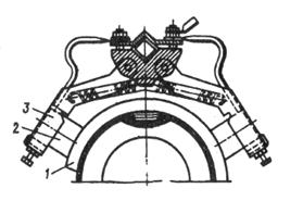
Figure 1 shows an example of the design of the machine; figure 2 - an example of a rotor machine with annular closing elements (schematically); figure 3 - an example of a machine rotor with helical closing elements (schematically); in fig. 4 - an example of an armature winding circuit of a machine with a ratio n c /f = 120 rpm Hz; figure 5 is a picture of the polarity of the magnetic field of the winding according to figure 4 in the air gap (sweep along the circumference); figure 6 is a view of the machine with a stator divided into two parts from the end when the shield is removed; figure 7 is an example of an armature winding circuit for a machine with a stator divided into two parts and a ratio of n c /f = 120 rpm Hz (circular scan); figure 8 is an example of an armature winding circuit with a ratio of n c /f = 240 rpm Hz.
A synchronous machine consists of a rotating part, a rotor and a fixed part of the stator. The rotor may consist of permanent magnets or may consist of a winding with direct current and magnetic circuit. To create current, an external force is used to turn the rotor: its rotating magnetic field induces an alternating electric current in the stator coils. The speed of this rotating field is called "synchronism speed".
Electric speed controller
A variable speed drive is an electronic device for controlling the speed and torque of an AC motor by determining the required frequency and voltage or input current. Their applications range from the smallest to the largest engines such as compressors. However, it should be noted that about a quarter of the world's electricity consumption is accounted for by electric motors used in industry. Variable speed drives remain unsprung while they reduce energy consumption.
Asynchronous machine with a squirrel-cage rotor contains a ferromagnetic stator 1 (see Fig. 1) with a multi-phase armature winding 2 (in the example of Fig.1 - three-phase) and a rotor 3. The stator 1 is fixed in the housing 4 and is made with grooves 5, 6 and 7 along the number of phases A, B and C of the winding 2. The grooves are beveled along a helical path along the axis of the machine. Essentially, the tooth-groove layer of the stator is a multi-start (m is the lead-in, where m is the number of phases of the armature winding) helical structure, and the phases A, B and C of the winding 2, placed respectively in the helical grooves 5, 6 and 7, are distributed in the axial direction. The rotor 3 in the active surface layer has a short-circuited winding, consisting of electrically conductive axial rods 8, distributed around the circumference, and closing the rods 8 elements 9, distributed in the axial direction. When this closing elements 9 can be made in the form of rings (see Fig. 2), which is quite technologically advanced. It is also possible to make closing elements 9 in the form of helical rods (see figure 3), which is structurally more complex and less technologically advanced, but provides improved machine performance by increasing the mutual inductance of the stator and rotor windings. In fact, helical grooves for such closing elements form a multi-start helical structure of the surface layer of the rotor (in the example of Fig. 3 - six-start). Anchor winding 2 machines is distributed in the axial direction of the section 10 (see figure 4), connected to each other in the usual manner. The sections 10 themselves are actually semi-coils with a helical-shaped active part 11 beveled along a helix and a straight frontal part 12. The frontal parts 12 are placed in a groove 13 specially made for them (see Fig.1). Due to the fact that the axial line of the frontal parts of the armature winding (slot axis 13) is the boundary of the abrupt change in the polarity of the stator field (see Fig.5), which leads to the creation of a braking torque in the machine, then to weaken the specified moment, the air gap in this area is made uneven by reducing the radial size of the stator (see figure 1).
Stator field rotation speed
As you can imagine, the current asynchronous engine has changed a lot since the work of those who looked at their cradle. In fact, his parentage is divided between 3 talented engineers, each of whom, on his own, brought significant value to make it a device that is now very popular for various purposes.
We owe it, in particular, to the principle of three-phase at 120 °. Finally, Mikhail Dolivo-Dobrovolsky will bring both ideas together and produce the first three-phase a synchronous motor with a squirrel-cage rotor, which we will discuss in more detail below. It is from this combination of ideas that the asynchronous engine is born, which appeared today in all industries and for consumer applications, but it was not won in advance.
Since the frontal parts 12 of the armature winding in the rotor create a bipolar field, which also causes a braking torque in the machine, then to weaken or eliminate this undesirable phenomenon, the axial groove 13 of the stator is made with a depth close in value to the radial size of the stator or through with the formation of a slot (see dotted line in the area of the groove 13 in Fig. 1). From the point of view of manufacturability and maintainability may be appropriate division of the stator 1 and armature winding 2 longitudinal-radial gaps 14 into two (Fig.6) or more parts. In this case, the sections of each part of the anchor winding 2 consist of two active parts 15 and two frontal parts 16 placed in the intervals 14 (see Fig.6 and 7). In the case of execution of the closing elements 9 of the rotor 3 helical (see figure 3) to ensure maximum electromagnetic moment machine, it is advisable to perform the steps of the "screws" of the helical grooves of the stator and rotor the same. Blending of the machine is expedient with a longitudinal-radial arrangement of sheets. The design of the machine with an external stator and an internal rotor has been described above. However, it is also possible to design with an internal stator and an external rotor, which, for technological or other reasons, may be more preferable.
Despite its great ease and cost of manufacture and low utilization, the induction motor suffers from some drawbacks that slow its development, sometimes giving an advantage to its competitors' mainstream synchronous technology. Powered by direct current, it has little torque when starting. Under the same conditions, he knows how to transmit only a fixed rate, without possible changes. Fortunately, the technical progress around power electronics has led to it using the principle of variable frequency, but also flow control, to force a high torque even at startup, so that the induction motor was able to pick up in advance again.
The invention is based on the idea of obtaining high rotational speeds in an asynchronous machine at low frequencies ah of the supply voltage (motor) and, conversely, low voltage frequencies at high frequencies rotation (generator) by forming an axial helical magnetic field traveling in the axial direction. The axial movement of such a field relative to elementary rotor circuits is equivalent to its rotation (see Fig.5). In this case, depending on the pitch of the "screw" of the field, its axial displacement by one pole division is equivalent to its rotation by a certain number of revolutions. For example, moving the field by one pole division with a pitch of the "screw" of the field equal to the pole division is equivalent to turning it by one turn, with a step of 0.5 - by two turns, etc. Since the pitch of the "screw" of the field is determined only by the pitch of the "screw" of the armature winding (stator slots), - these values are equal to each other, - then the relationship between the voltage frequency f and the rotation frequency of the stator field (synchronous rotation frequency) n c is determined from the following reasoning.
Due to a few minor changes, because technically, only the rotor is different. The engine will support the same number of engines. In the end, the high-speed train will benefit from a clear increase in efficiency and a slight increase in power from 800kW to 280kW.
Just like its synchronous motor cousin, the stator is made up of coils, typically 3, which, alternately criss-crossed by current, will induce a rotating magnetic field. The rotor is formed from rigid aluminum or copper conductors mounted in a short and checkered pattern, hence the nickname "squirrel-cage rotor".
The displacement of the stator field with the "screw" pitch t B1 = per pole division corresponds (equivalently) to the rotation of the field by one revolution and the time 1/2f c = 1/20 f min. Taking into account the inversely proportional dependence of the field rotation on the relative pitch of the "screw" of the field (slot) of the stator t B1 / shown above, the field rotation frequency (synchronous rotation frequency) is determined as follows: n c =120f/t B1 =120fn B1 rpm, where n B1 =/t B1 is the number of turns of the stator slot per pole.
If an aluminum rotor is molded in a foundry, the copper alloy has until recently been offset for technical reasons. Now, to increase productivity, they are also produced in the industry. The rotating magnetic field of the stator will cause an induced field in the rotor. In addition, the terms "motor armature" and "motor rotor" are used in an equivalent way, with the latter magnetic field tending to match the stator indicator but failing to catch it: this is slippage.
Strategic selection of manufacturers
Thus, the rotor speed is always slightly less than the timing when running in the stator. It was this situation that gave the asynchronous motor its name. The induction motor is probably the most economical to manufacture. It is also the one whose industrial value is the most stable. Since there are no magnets in the rotor, which are made of magnetic iron sheets and aluminum, and less often copper.
In the considered example, where n B1 =/t B1 =1, at a frequency f = 50 Hz n c = = 6000 rpm, which was impossible to provide in an asynchronous machine. By changing n B1 it is possible to achieve any ratios n c /f.
It should be noted that in terms of physical processes, the operation of the machine in all modes (engine, generator, brake) is no different from the operation of a conventional asynchronous machine, where the rotor rotates with some slip relative to the rotating stator field.
Modes of operation of an asynchronous machine
With a strong increase in demand for some raw materials, which make up the most powerful magnets, this is a definite price stability advantage - these "rare earths" are actually very poorly named. The “land” is historical, it itself is already poorly adapted. These are actually minerals that are quite widespread on Earth.
What is really problematic and explains the price of these elements is that their quantity is very low due to the deposit. In short, there are many on our blue planet, but it spreads ubiquitously in small veins, making them very expensive to exploit.
Due to its simplicity and reliability, as well as the possibility of obtaining theoretically any high speeds at low mains frequencies and voltage of any low frequencies at high speeds, the proposed machine as an engine can find wide application in a household electric drive (mixers, coffee grinders, hair dryers, etc.) instead of unreliable collector motors, as well as in medium and large industrial high-speed electric drives (threshers, centrifuges, etc.), where frequency converters can be excluded, and as a generator - in power plants with high-speed (turbine) drive, where reducers can be excluded.
Fig.2. squirrel-cage rotor
Moreover, their use has made them geostrategic resources that everyone is trying to capture in countries, some of which do not have a stable democratic regime. This is why engine manufacturers are increasingly looking to limit or even dispense with these so-called rare soils.
The induction motor does not use magnets, so it is immune to rare earth problems and can claim to be the cheapest to manufacture the entire electrical unit family. But there are also analogues. Because if the motor itself isn't expensive, then the same can't be said for the electronics needed to manage speed changes. This essential material, except for use in three-phase fixed speed, worldwide loses the financial advantage of an asynchronous solution.
1. ASYNCHRONOUS MACHINE WITH A SHORT-CLOSED ROTOR, containing a stator with a ferromagnetic core with a cylindrical active surface layer with grooves and a multi-phase winding placed in them, and a rotor concentric with the stator with a ferromagnetic core and electrically conductive axial rods in its active surface layer and elements closing the rods, characterized in that that, in order to expand the scope by providing a given ratio of rotational speed to voltage frequency while maintaining simplicity and reliability, the stator slots are made beveled along a helical path along the axis of the machine, and the stator winding and closing rods of the rotor elements are distributed in the axial direction, and the closing elements rotor are placed in its active surface layer.
You can't slip it in an electric car. After you operate subtly, this design design has shown amazing performance for more than a century. If it is able to turn at high speed, it can now provide very important torque right from the start, making it ideal for electric propulsion.
On the other hand, the heat engine will never be able to even out with rising production costs, Maintenance and consumption, which will show up very clearly in his disfavor. Peculiarity induction motor roadster? Its entire design was geared towards achieving maximum performance and efficiency. Thus, the connecting rods of the rotor are made of copper. It's not groundbreaking, except that here the copper was pressure-cast in a foundry directly onto the rotor.
2. The machine according to claim 1, characterized in that the closing rods of the rotor elements are made in the form of rings located in the annular grooves made in the core perpendicular to the axis of the machine.
3. The machine according to claim 1, characterized in that the closing rods of the rotor elements are made in the form of helical rods placed in grooves made beveled along the helical path along the axis of the machine, and galvanically connected to the axial rods at the points of intersection with them.
The design of asynchronous machines with a squirrel-cage rotor
This is the current value in terms of product quality. The sheets folded to form the stator and the rotor are exceptionally thin and more numerous to reduce eddy current losses. caused by magnetic fields will lead to energy losses if the assembly is made from a single block of iron.
We understand the best performance and performance from this roadster's conventional traction chain. With constant progress every year, the efficiency of the induction motor is now about 88%, when the best sports cars with state-of-the-art internal combustion engines barely reach 30%.
4. The machine according to claims 1 to 3, characterized in that the stator winding is made of sections, each of which consists of a helical active part and a straight frontal part, and the frontal parts of the sections are placed in an axial groove made in the stator.
5. The machine according to claims 1 to 4, characterized in that the air gap along the circumference of the stator bore in the region of the frontal parts of the stator winding is made uneven by reducing the radial size of the stator.
6. The machine according to claims 1 to 5, characterized in that the axial groove of the stator is made with a depth close in value to the radial size of the stator, or through in the radial direction with the formation of a slot.
Structural forms of execution of electrical machines.
Basic information about serial asynchronous motors.
Modes of operation of an asynchronous machine.
The principle of operation of an asynchronous machine.
The device of an asynchronous machine.
Lecture #2
Navigation systems
Irkutsk branch of MSTU GA
Irkutsk, 2007
Asynchronous electrical machines
Electric cars
LECTURE #9
AND FLIGHT AND NAVIGATION SYSTEMS
DEPARTMENT OF AVIATION ELECTRICAL SYSTEMS
IRKUTSK BRANCH
CIVIL AVIATION
MOSCOW STATE TECHNICAL UNIVERSITY
by discipline
for students of specialty 160903
Chair Aviation electrical systems and flight control
APPROVE
Head of the Department of Nuclear Power Plant and PNK
Candidate of Technical Sciences, Associate Professor Mishin S.V.
« 14 » Martha 2008 G.
By discipline: Electric cars
Lecture topic: Asynchronous electrical machines (2 hours)
LITERATURE
1. Kopylov B.V. Electric cars. M., 1988
VISUAL AIDS, APPS, TCO
1. Multimedia installation
Discussed at the meeting of the department
« 14 » Martha 2008 city, protocol no. 8/07
An asynchronous machine consists of two main parts separated by an air gap: a stationary stator and a rotating rotor. Each of these parts has a core and a winding. In this case, the stator winding is connected to the network and is, as it were, primary, and the rotor winding is secondary, since energy enters it from the stator winding due to the magnetic connection between these windings.
According to their design, asynchronous motors are divided into two types: motors with a squirrel-cage rotor and motors with a phase rotor. Consider the device of a three-phase asynchronous motor with a squirrel-cage rotor (Fig. 1). Engines of this type are the most widely used.
Fig.1. The device of a three-phase asynchronous motor with a squirrel-cage rotor:
1, 11 - bearings; 2 - shaft; 3, 9 - bearing shields; 4 - terminal box; 5 - rotor core with a short-circuited winding; 6 - stator core with winding; 7 - body; 8 - stator winding; 10 - fan; 12 - fan casing; 13 - outer ribbed surface of the body; 14 - paws; 15 - ground bolt
The stationary part of the engine - the stator - consists of a housing 7 and a core 6 with three-phase winding 8. The engine housing is cast from aluminum alloy or cast iron, or made by welding. The considered engine has a closed blown design. Therefore, the surface of its body has a number of longitudinal ribs, the purpose of which is to increase the cooling surface of the engine.
The housing contains the stator core 6, which has a laminated structure: stamped sheets of thin sheet electrical steel with a thickness of usually 0.5 mm are covered with a layer of insulating varnish, assembled into a package and fastened with special brackets or longitudinal welds along the outer surface of the package. This design of the core contributes to a significant reduction in eddy currents that occur during the remagnetization of the core by a rotating magnetic field. On the inner surface of the stator core there are longitudinal grooves in which the slotted parts of the stator winding are located, connected in a certain order by the frontal parts located outside the core on its end sides.
In the stator bore there is a rotating part of the engine - a rotor, consisting of a shaft 2 and a core 5 with a short-circuited winding. Such a winding, called the "squirrel wheel", is a series of metal (aluminum or copper) rods located in the grooves of the rotor core, closed on both sides by short-circuiting rings (Fig. 2, a). The rotor core also has a laminated structure, but the rotor sheets are not coated with insulating varnish, but have a thin oxide film on their surface. This is sufficient insulation to limit eddy currents, since their magnitude is small due to the low frequency of magnetization reversal of the rotor core. For example, at a mains frequency of 50 Hz and a nominal slip of 6%, the remagnetization frequency of the rotor core is 3 Hz.
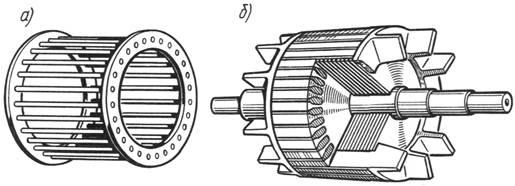
Fig.2. Squirrel-cage rotor:
a - winding "squirrel cage"; b - a rotor with a winding made by injection molding;
The squirrel-cage rotor winding in most motors is done by casting the assembled rotor core with molten aluminum alloy. At the same time, short-circuiting rings and ventilation blades are cast simultaneously with the winding rods (Fig. 2, b).
The rotor shaft rotates in rolling bearings 1 and 11 located in bearing shields 3 and 9.
The engine is cooled by blowing the outer finned surface of the housing 13. The air flow is created by a centrifugal fan 10 covered by a casing 12. On the end surface of this casing there are holes for air intake. Motors with a power of 15 kW and more, in addition to the closed one, also make a protected version with internal self-ventilation. In the bearing shields of these motors there are holes (blinds) through which air is driven through the internal cavity of the motor by means of a fan. In this case, the air “washes” the heated parts (windings, cores) of the engine and the cooling is more efficient than with external blowing.
The ends of the phase windings are brought out to the terminals of the terminal box 4. Typically, asynchronous motors are designed to be included in three-phase network for two different voltages, which differ by a factor. For example, the motor is designed to be connected to a network for voltages of 380/660 V. If the network line voltage 660 V, then the stator winding should be connected with a star, and if 380 V, then with a triangle. In both cases, the voltage on the winding of each phase will be 380 V. The conclusions of the phase windings are placed on the panel in such a way that it is convenient to connect the phase windings by means of jumpers, without crossing the latter (Fig. 3). In some low power motors, there are only three clamps in the terminal box. In this case, the motor can be connected to the network for one voltage (the connection of the stator winding of such a motor with a star or a delta is made inside the motor).
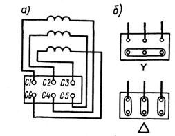
Fig.3. The location of the stator winding terminals (a) and the position of the jumpers
when connecting the stator winding with a star and a triangle (b)
Mounting of the motor at the place of its installation is carried out either by means of legs 14 (see Fig. 1) or by means of a flange. In the latter case, a flange is made on the bearing shield (usually on the side of the protruding end of the shaft) with holes for mounting the engine on the working machine. To protect operating personnel from possible injury electric shock motors are supplied with ground bolts 15 (at least two). circuit diagram inclusion in a three-phase network of an asynchronous motor with a squirrel-cage rotor is shown in Fig. 4, a.
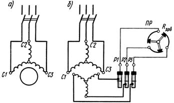
Fig.4. Schematic diagrams of the inclusion of three-phase asynchronous motors with squirrel-cage (a) and phase (b) rotor
Another type of three-phase asynchronous motors - motors with a phase rotor - structurally differs from the considered motor mainly in the rotor device (Fig. 5). The stator of this motor also consists of a housing 3 and a core 4 with a three-phase winding. It has bearing shields 2 and 6 with rolling bearings 1 and 7. Feet 10 and a terminal box 9 are attached to the body 3. However, the rotor has a more complex design. A laminated core 5 with a three-phase winding is fixed on the shaft 8, similar to the stator winding. This winding is connected by a star, and its ends are connected to three slip rings 11 located on the shaft and isolated from each other and from the shaft. To make electrical contact with the winding of a rotating rotor, each slip ring 1 (Fig. 6) usually has two brushes 2 placed in brush holders 3. Each brush holder is equipped with springs that ensure that the brushes are pressed against the slip ring with a certain force.
Asynchronous motors with a phase rotor are more complex and less reliable, but they have better control and starting properties than motors with a squirrel-cage rotor. A schematic diagram of the inclusion in a three-phase network of an asynchronous motor with a phase rotor is shown in Fig. 4, b. The rotor winding of this motor is connected to the starting rheostat ETC , which creates additional resistance in the rotor circuit R ext .
A plate is attached to the body of the asynchronous motor, which indicates the type of motor, manufacturer, year of manufacture and nominal data (net power, voltage, current, power factor, speed and efficiency).
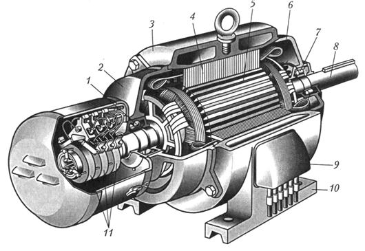
Fig.5. The device of a three-phase asynchronous motor with a phase rotor:
1, 7 - bearings; 2, 6 - bearing shields; 3 - body; 4 - stator core with winding; 5 – rotor core; 8 - shaft; 9 - terminal box; 10 - paws; 11 - contact rings
We advise you to read
, diagnosis, treatment Treatment of urogenital chlamydia") Chlamydia urogenital - description, causes, symptoms (signs), diagnosis, treatment Treatment of urogenital chlamydia
Chlamydia urogenital - description, causes, symptoms (signs), diagnosis, treatment Treatment of urogenital chlamydia The benefits and significance of hydroamino acid threonine for the human body L threonine what
 To wait or not to wait for a guy from the army For what reason can they be commissioned from the army
 Baked apples with cottage cheese Baked apples with cottage cheese

