The electrical system of a car, figuratively speaking, is a complex of a power plant and a network of consumers adapted to the special requirements of the system. Distinguish between electrical equipment of the engine and electrical equipment of the car.
Below, only the electrical equipment of the car is considered, in particular, the main network of consumers, consisting of lighting and signaling devices, glass cleaner and washer, radio, switching devices, electrical wires, as well as battery mounting parts, since the latter are installed on the body. Recall that other parts of electrical equipment (ignition coil, voltage regulator, relay, etc.) are attached to the body, but they do not require special constructive solutions. With the existing variety of electrical equipment, we will focus only on the most important, concerning the design and design of the body. Corresponding "electrical" problems are described only in connection with the above.
Outdoor lighting and light signaling system
At night and in poor visibility, vehicle lighting has a dual function: to help you see and be seen. Accordingly, a distinction is made between headlamps for the first task and lamps for the second task. The car usually has:
- headlights with high and low beam;
- additional fog lights or high beams are possible;
- parking and marker lights;
- rear lights and rear fog lights;
- license plate lights;
- reversing lights.
Light signaling includes:
- direction indicators front and rear;
- alarm system;
- braking signal.
Only prescribed or approved headlights and lamps may be fitted to the vehicle. There are many international regulations regarding the location, relative positioning of headlights, their lighting characteristics and visibility. In principle, a characteristic symmetrical arrangement of signals must be observed in front and behind the vehicle, i.e. the main headlights and lamps must be located symmetrically with respect to the longitudinal axis of the vehicle and approximately at the same height. In most countries, headlamps and lanterns are subject to classification and testing to meet national requirements. In order to simplify this process, as well as for constructive and stylistic reasons, it is very often preferred to combine lighting devices into one unit; this greatly facilitates the installation of lighting devices in the body. The existing variety of possibilities and forms allows us to give only the most general information on the design of lanterns, headlights and blocks.
The unit should have simple, as even as possible, mounting surfaces that are easy to mount and seal.
The comparison shows the advantage of the American dipped-beam lighting system in terms of brightness and illumination (with a greater risk of glare) is exactly the same as in relation to illumination with a European four-head lighting system with 146 mm headlights, made in imitation of the American system. By using halogen lamps, this disadvantage can be reduced by ensuring easy replacement, preferably using the unit mounting from the outside (screwing from the inside); since at present almost all appliances are made sealed, openings in the body should be large enough to allow access to the appliances from the inside (for example, to replace the lamp) and to facilitate the laying and checking of electrical wires.
For current rectangular headlamps, it should be ensured that the width and height of the headlamp have a ratio acceptable to obtain the required lighting performance, and that it remains possible to install headlight lamps that comply with American Requirements (two headlamps with a diameter of 178 mm or four headlamps with a diameter of 146 mm , or a rectangular headlight 114X152 mm), in the same cutout on the body. Recall that round headlights make better use of the luminous flux (normalized to the diameter of the reflector) and, for reasons of visibility and less dazzle for oncoming drivers, the reflective surface illuminated in the low beam should ideally be 150 cm2, which corresponds to a headlamp with a diameter of approximately 190 mm.
In rectangular headlights, according to research by Bosch, the determining parameter for low beam illumination is the width of the reflector (the diameter of the reflector truncated at the top and bottom). Therefore, small headlights should not be used. The headlights must have a diameter (equal to the width) of at least 190 mm and a height equal to 0.8-0.65 of the width. In the case of using a headlight lamp, it should be borne in mind that the sidelight (parking light) and direction indicator must be installed separately.
The headlamps can be fitted with two tungsten filament bulbs, as well as hologen bulbs (which is preferred). When using four headlights (such a system developed in the USA), you should pay attention to the following: in the European version of the low beam, as opposed to the American one used in headlight lamps, to obtain luminous flux only the top half of the reflector is used, resulting in less glare from these headlights. Illumination and visibility in this case are greatly reduced, despite the increased electrical power light threads. Therefore, in Europe, it is not recommended to use 146 mm headlights adopted from the USA (due to their easy replacement). Their installation is justified only if used halogen lamps. It is better to provide for the installation of larger dipped beam headlights. The diameter of the headlight in the plane of the exit of the light beam should be approximately 180 mm. The dipped and main beam headlights can be located both horizontally in a row one next to the other, and vertically one above the other.
Since, with the asymmetric dipped beam adopted in Europe, the boundary between light and darkness is very clearly defined and its position depends on the position of the headlights in height, the headlight range should be easily adjusted without the use of a special tool, preferably from the driver's seat using remote control. Legislation requires compliance in EEC countries with certain limits for the inclination of the dipped beam beam, regardless of the vehicle load. If for this no special measures are taken for the design of the vehicle suspension (for example, to provide for adjusting the level of the body), then these requirements can be observed only by introducing manual or automatic adjustment of the illumination zone. In the process of designing the body, it should be possible to install such an additional device. In the same way, from the very beginning of the design of the body, the possibility of installing more and more popular headlight washers and cleaners, which are powered by one or two small electric motors, should be considered. It is necessary to ensure that they have easy access.
Many experimental attempts and studies are known to overcome the main drawback of the European low beam - high dependence on the position of the headlights - by using other systems, as well as to prevent glare. The so-called polarized light provides ample opportunities for this. Although technically this question can be completely solved, however, in the practical introduction of polarized light, such significant difficulties arise (for example, mixed traffic, re-equipment of the park) that they cannot be ignored.
In fact, with the right headlights, additional headlights are not needed, and in part even harmful, since they can hardly be used with an ever-increasing traffic density. The use of additional high-beam headlights is justified only in special cases of operation (driving at night, in sports cars). It should not be forgotten that the difference in light intensity between the far and near light is very large. This makes it difficult to adapt vision, and hence visibility. Additional headlights (only allowed in pairs, they should not be too close to the longitudinal axis of the car and in no case should they block the openings for fresh cold air.
In contrast, it is useful to have paired fog lights. To avoid dazzling drivers of oncoming vehicles, fog lamps should be located as low as possible, at a distance of no more than 40 cm from the outer contour of the car, so that they can be used simultaneously with the parking light. Only in this case, the fog lights will to some extent correspond to their intended purpose. When designing, it is advisable to provide for the possibility of installing fog lamps in the front of the car in order to exclude unqualified installation during installation at the request of the buyer. Quite a good solution is to place the fog lights under the front bumper. Recall that the headlights can be closed or recessed, in the USA this is only permissible if certain regulations for their operation are met.
Clearance lamp, brake lamp, reversing lamp and rear turn signal, and reflectors most often combined into one unit, easily installed on a car. From the point of view of lighting engineering, it would be better to group these lighting devices into two nodes (direction indicator - position lamp - reflector and brake light - reversing lamp). When combining a position lamp and a stop lamp, it should be taken into account that there must be a ratio of 1:5 between the luminous intensity of these devices, which can be achieved using a 5/18 W double-filament lamp and an optimally designed reflector. The left and right position lamps must be protected separately.
Mandatory lanterns (lantern) for lighting the rear license plate must provide sufficient visibility of the license plate and must not radiate light backwards. This should be taken into account when designing and placing these lights. The location of the lights is chosen arbitrarily, you can even use the back door if the side lights are firmly fixed. In order to accommodate a film license plate, the installation of which will be introduced in the near future (probably within the framework of the EEC, at least in Germany), it is necessary to provide a flat area of sufficient size on the rear panel (width 520 or 340 mm, height 120 or 240 mm) .
When installing rear lights, which are legal in many countries (required in the US), care should be taken to ensure that they do not dazzle drivers of vehicles moving behind. This can be achieved by using an appropriately designed reflector and tilting the light beam down. In some countries, one fog light is allowed, which can be placed on the left side and separate from the rear light. The fog lamp is switched on separately from the other lamps (only together with the headlights) and is controlled by the yellow control lamp on the instrument panel. However, according to the EU Directive, two fog lamps are required as standard, which is why they are now usually integrated into the rear lamp.
Switching elements
Turning on the headlights, parking lights and lamps is best done with a single lever switch. However, it is possible to provide separate switches for the parking light and headlights (with a mechanical interlock that turns on the parking light whenever the headlights are turned on). Switching the headlights with the turn signal combination lever is now standard and should always be provided. With the help of this lever, as you know, the direction indicators, the windshield washer and wiper system, and the headlight signaling are usually switched on. The direction indicators are activated via an electronic relay that provides a flashing mode of operation, if appropriate, this relay also provides an alarm system. The latter, however, must be switched on using a separate switch with a red control lamp. The relay must give optical and acoustic control signals and is therefore located in the passenger compartment. Note that the turn signal thermomagnetic relays cannot control the alarm system, so a second relay is needed (you should provide a place for its placement). The hazard warning switch can be located in any suitable location, such as on the steering column.
Sound signals
prescribed in all countries mandatory installation sound signal, most countries have sound intensity regulations. The use of signaling devices with different tone alternations for private cars is prohibited in Germany. When placing sound signals, care should be taken to ensure that body parts do not interfere with the propagation of sound. The horns can be placed behind the grille where they are protected to some extent from pollution and precipitation. The audibility of the signals is highly dependent on the speed of the vehicle. There are two types of beeps that differ in their sound.
The horn membrane has a specific fundamental sound frequency (approximately 400 Hz) and radiates in the high-pitched region (approximately 1800-3500 Hz). Therefore, the tone of the horn signal is harsh and piercing at the same time. To improve the sound, the horns are used in harmonically coordinated (third) pairs. With the help of an elastic suspension, the influence exerted on the sound by vibrations of body parts and their rattling (exclusion of acoustic and mechanical short circuits) should be prevented, in connection with which the free propagation of sound is of particular importance.
Fanfare (electro-pneumatic horn) has a wide frequency range, since in this case the air column oscillates in a pipe (spiraled). Thanks to this, the tone is softer and more pleasant, but, contrary to the general opinion, less penetrating. In addition, fanfares are not so sensitive to vibration lock. All horns (Actuated by a switch through a relay, as they are highly voltage dependent and very susceptible to poor contact.
windshield wiper
Mandatory installation of a windshield wiper with the appropriate drive is prescribed in all countries, however, the presence of a washer is not required everywhere, although it has long been a part of the standard equipment of the car. The cleaner uses an electric drive, most often with two speeds.
Since visibility is severely reduced and sometimes completely lost due to dirt on windows, rain, etc., a well-functioning wiper and washer is an important factor in improving safety. The requirements for the minimum size of the area to be cleaned (as well as for the defrosting zone) first appeared in the USA (Federal Standard 104) and were soon adopted into UNECE Regulations and EEC directives.
The field of view is divided into several zones, each of which has its own degree of cleaning, expressed as a percentage. Thus, the choice of parameters of the cleaner and washer to a large extent depends on the size of the glass, its shape, position relative to the driver's seat (center of the eyes).
At modern forms windshield, the requirements mentioned above can best be met with equally or oppositely moving wiper arms. The brushes are driven by an electric motor with a built-in worm gear. The position of the swing centers (arms) and their length are largely determined by the desired (and prescribed) cleaning area, as by the length of the brushes. By changing the inclination of the brush relative to the arm, cleaning in corners can be improved and a more acceptable starting position can be obtained. Heavily curved and non-spherical glasses only by using brushes with an even distribution of contact pressure (Tricot principle) and by matching the curvature of the brush to the curvature of the windshield as much as possible, it is possible to obtain the required cleaning zone.The contact pressure at the end of the lever is approximately decreases, so it would be necessary to provide special pressure pads, which, however, impair visibility.
The slope and shape of the windshield have a strong influence on the performance of the wiper, which should be checked; at high speeds of air flow in the wind tunnel. The power consumed by the wiper fluctuates greatly, since the shear resistance of the brushes is significantly less when the glass is wet than when the glass is almost dry or dry. In accordance with this, the moment of braking of the electric motor and the forces in the levers and hinges also change greatly. The moment (according to Bosch) varies from 7 to 25 N-cm. The dynamic forces in the hinges are also very high. It is more expedient to use ball joints with Teflon liners, which do not require lubrication and provide a clear spatial movement of rods, which, as a rule, are not parallel to the axes of the wiper arms and the drive crank. It is best to place the wiper elements in an easily accessible place under the hood, and it is preferable to pre-mount the system (electric motor - traction - wiper arms) on a stable supporting frame, which is then installed on the body together with rubber soundproofing gaskets. Thus, an accurate fixation of the relative position of the elements and an optimal distribution of forces are achieved.
Recall the design common in the United States with a closed initial arrangement of the wiper arms, which, for inexplicable reasons, has not received distribution in Europe. The automatic intermittent operation of the cleaner in light rain or damp fog is very practical. In this case, the wiper is switched on at regular intervals (sometimes adjustable). This design requires either a dedicated wiper switch position or a separate intermittent wiper switch (with adjustable spacing) for which space must be allocated in the part of the instrument panel where the switches are located.
Glass washers
The washer has either one central jet that sprays water in two directions, or two separate jets, which are usually attached to the hood, but it is better to attach them to any rigid body part located in front of the wind window; they must be adjustable so that the direction of spray can be optimized.
Washers must be powered by an electric pump; by a certain combination of switches, the cleaner is switched on after water is sprayed and the brushes make several strokes. The pump and time relay are most often attached to the washer reservoir. The latter, in order to prevent the liquid from freezing, is best placed in the engine compartment.
Since the pipelines of the system are constantly filled with liquid, the possibility of freezing them is very high, so it is necessary to add antifreeze to the liquid used for washing glass. Often this is not enough, since the antifreeze evaporates in the area of \u200b\u200bthe jet holes. Therefore, it is recommended to use a recessed installation of jets. The mentioned recessed installation of the cleaner is very rational, especially in the case when warm air escapes from the engine compartment through the gap formed. US Federal Standard 104 contains requirements for the minimum washable area (in % of glass area cleaned), as well as for reliable operation in frosty conditions. These requirements are very difficult to fulfill without making special design decisions. Therefore, heated jets were developed, the use of which eliminates freezing.
A few more words about headlight washer systems. Their design depends entirely on the shape and placement of the headlights. The minimum requirements for headlight washers, similar to those for windshield washers, are based on light transmission measurements during and after cleaning and washing the headlight glass.
Car radio, antenna, interference suppression
A car radio has completely different operating conditions and functions than a conventional one. First, the sensitivity, selectivity, interference rejection, gain, and AGC system, due to the lower antenna efficiency and highly fluctuating input energy, must be much higher; secondly, the influence of atmospheric disturbances, thermal and mechanical loads, as well as the labor intensity of use should be as minimal as possible.
Simplify the installation of radio equipment on a car by separating the radio receiver from the loudspeakers, if they are small. The development of semiconductor technology and electronics contributes to the creation of equipment of any power. Despite this, it cannot be ignored that at present, in the conditions of driving a car, the reception of radio transmissions serves more for obtaining information than for satisfying cultural needs, and the quality of reception is highly dependent on the level of noise generated by the movement of the car. The use of additional devices specially designed for receiving radio transmissions in traffic only emphasizes this phenomenon.
To simplify the use, only devices with a fixed station tuning should be used, preferably with an additional transmitter station finder, since manual control of the radio receiver is an element that increases the danger of movement.
Consider especially the placement of the antenna and loudspeakers. Significant improvement in reception quality can be achieved if the following guidelines are taken into account.
The antennas of car radios are the more effective, the farther they are removed from the mass of the car (contour). For these purposes, whip antennas that extend to a height of approximately 0.9 m are best suited. In addition, such antennas are insensitive to the direction of radiation of the transmitting station. As a result, roof-mounted fold-out antennas often provide better reception than conventional windshield-mounted, telescopic, and folding whip antennas. However, the quality of radio wave reception is so dependent on the vehicle's own parameters that the most suitable antenna position should always be determined from test results. It goes without saying that the antenna should be as short as possible and noise-resistant. An antenna located on the side and inaccessible from the driver's seat must have an automatic electric drive. When matching the antenna, as well as the radio receiver, preference should be given to the VHF range and medium waves.
Loudspeaker placement, especially stereo radio equipment, should be carefully considered. Many years of practice have shown that subjectively, the sound coming in the direction of sight is perceived better. Therefore, it is best to install one loudspeaker in the center of the instrument panel, or to increase the completeness of the sound (or with stereo radio equipment) - one loudspeaker each in the left and right parts the instrument panel so that the sound comes at an angle to or away from the instrument panel.
Quite acceptable is the location of the loudspeakers one by one in the left and right parts of the roof frame, approximately in the middle of the cabin. By appropriately designing the loudspeaker grille, the sound can be propagated forward and backward. The loudspeaker should, if possible, be placed in a soundproof enclosure to prevent acoustic low-frequency short circuiting of the waves generated by the rear side of the cone. If the speakers are located in the front and back parts cabin, it is necessary to provide for the adjustment of sound distribution. When creating stereo sound, this must also be observed for the left and right speakers.
All this data is given because the bodybuilder must know the requirements for the installation of radio equipment and foresee the place for its placement.
The quality of radio reception in a car depends on the general criteria mentioned above and on shielding (suppression of interference sources). In addition to power lines, electrified railways and other interference coming from outside (including other cars), the main source of interference is the ignition system of carburetor engines. However, wiper motors, electrostatic charges, and poor contact and ground connections metal parts bodies (bumpers, fenders, hoods) can cause functional interference. Therefore, so-called suppression of interference from the ignition system by means of resistors is prescribed for all vehicles. For the radio to work without interference (as, indeed, for all radio equipment in general), this is not enough, it requires additional funds interference suppression from the generator, its regulator, the wiper motor and other electric motors. Sometimes, in addition, it is necessary to provide a ground wire between the hood or trunk lid and the body. The bodybuilder must take into account the fact that large parts having a threaded fastening on the body must have close contact with it, and the contact surfaces of the part and the body must be free from enamel (sometimes additional tinning should be provided). In addition, there must be no corrosion.
Car electrical circuits, battery mount
Car electrical circuits I serve to distribute the current between individual devices and, in accordance with the many consumers, they are very branched. A complete picture of the electrical equipment of the car gives a general electrical circuit.
The electrical network of the car is mainly single-wire, the negative pole of current sources in Europe is connected to ground.
When placing the battery, it should be ensured that it is connected, if possible, with a short wire to the starter and located in an easily accessible place. For safety reasons, the battery should not be placed too close to the front edge of the vehicle. In addition, care should be taken to ensure that body parts do not corrode from the emitted vapors of acid and gases. To do this, they must be protected or closed. The fastening shall be strong enough that the battery will not come off during the impact test. The currently accepted bottom attachment with a welded or screwed holder adequately satisfies this requirement. It is best to have the battery rest on the lip of the front wheel mudguard or on the bracket attached to it, or on the front engine bay shield if there is room for that.
Usually not all branches electrical circuits protected by fuses. The main energy consumers are grouped in such a way that 8-10 fuses can be dispensed with, and additional energy consumers (radio, fog lights, etc.) are protected separately. Some devices, such as headlights, are often not protected, because experience shows that they rarely fail, and in the event of a malfunction, it is easy to find (for example, broken lamp filaments). If it is nevertheless decided to protect the headlights, then a fuse must be provided for each thread. The fuse box should be located in an easily accessible place in the passenger compartment or in the engine compartment. The block must be marked with information about the protected circuits so that it can be used when searching for the cause of the failure. Currently, the fuse box is combined with a diagnostic block and placed in the engine compartment, in addition, this place has good access to the relay. The choice of fuse (5.8 or 15 A) depends on the current consumed by the device, which is also decisive when choosing the cross section of electrical wires. Knowing the usual voltage of the on-board network for a car, equal to 12 V, you can easily calculate the current consumption.
Overloaders, used in the USA instead of fuses, are not widely used in Europe for cost reasons.
Electrical wires
The electrical wires must have a cross-section corresponding to the current drawn by the connected appliances, and the voltage drop due to the resistance of the electrical wires must be minimal.
IN general case use electrical wires with copper conductors, the cross-sectional area of which is 1-2.5 mm2. Wires with a cross-sectional area of less than 1 mm2 are not recommended, as they have insufficient mechanical strength.
A large number of electrical wires, a large branching of the vehicle's electrical network, as well as the requirement for ease of installation lead to the need to combine individual electrical wires of certain groups of electricity consumers into bundles, for example, for the front of the car (headlights, engine compartment lighting, sound signals), for power supply to the passenger compartment (devices, switches, ignition lock) and for the rear of the vehicle (parking light, brake light, turn signal and reversing lights or rear lights), which are connected to each other using multi-terminal plugs. This makes troubleshooting easier. A useful innovation is the introduction of a diagnostic system into the electrical network, the connector of which is located in the relay and fuse box, which allows you to check the performance of the most important units.
Recently, great efforts have been made to simplify on-board electrical network by eliminating individual electrical wires and introducing a central wire used for a multiplex (single-wire) distributed consumer control system, similar to how it is done in telephone communications. Although these developments are still in their early stages, they are of particular interest, since their implementation will increase the reliability of operation and, possibly, reduce costs. This would significantly simplify the vehicle's on-board network and lead to improved monitoring and diagnostics of failures of individual devices. In the future, this simplification is all the more necessary, since electronic control and monitoring devices require a developed electrical network that is independent of the vehicle's power circuits.
Such an integral element of the vehicle device as the electrical equipment of a car is a complex of devices and parts that generate, transmit and act as consumers of electricity in various vehicle systems.
It is an interconnected system in which electronic and technical and electronic circuits and complexes that provide the necessary functionality of the motor, transmission drive and suspension of the car, are responsible for ensuring safety when driving on the road, the clarity of the operation of all car systems, managing additional options and giving comfort to participants in the movement.
The main indicators of the power supply of the vehicle's on-board network
To supply electricity to the vehicle's power supply system, direct current is almost always used. On the first assembly cars, a voltage of 6 V was used, now - 12 V on "cars" and small trucks and 24 V on heavy diesel trucks and road trains.
The wiring is used single-pole, since the so-called wire is used as a wire with a minus sign. "mass" - the body and frame of the car made of metal. It does wired system simpler and cheaper, but significantly increases the possibility of short circuit modes.
Vehicle power supply
The majority of modern cars use an alternator as a recovery power source. synchronous type with electric drive from the main engine; the generated alternating current from the generator is transmitted to a rectifier, which is usually located in the generator.
When the engine is off, for the initial start of the power unit, it is necessary to have a battery with an appropriate capacity that allows you to start the car, including in cold weather, when a significant effort is required to start the engine. When the power unit is running, the alternator recharges the battery.
Previously, on cars of an earlier assembly, generators were used direct current. A feature of the operation of such generators is the fact that required voltage to recharge the battery, it will be supplied to the battery only at significant engine speeds, since at low engine speeds, the on-board current sources were powered from the battery, which led to a forced discharge of the battery cans.
Sometimes, if necessary, an additional generator device driven by a small motor is mounted on the car, which makes it possible to provide electricity to energy sources regardless of the car's engine.
Auxiliary Electronic Devices
Such devices include:
- switches
- switches,
- relay,
- circuit breakers,
- socket pads.
Switches are used to interrupt the operation of an electrical circuit.
Switches are used to change operating modes.
Relays are designed to close and open different sections of electrical circuits for certain upgrades of electrical values.
Fuses are needed to save products or parts from short circuit mode.
Connector pads are used for tighter contact electrical elements chains.
Vehicle lighting
Devices light lighting cars are divided into external and internal devices.
These consumers include:
1. Outdoor devices include dipped and main beam headlights, “dimensions”, “turn signals” with repeaters on the wings, which also work in the “emergency gang” mode, brake lights, stern lights, license plate lights, “fog lights”, and sometimes decorative lamps.
2. Light bulbs are defined for internal use devices: interior lights, engine compartment lights, trunk lights, the so-called. "glove box", instrument panels, etc.
- Starter
- Ignition system
- Electronic control unit
- Electric power steering
- Motors for fans, windshield wiper motors, window lifters, etc.
- Electric servo seats
- cigarette lighter socket
- Audio system
- Sound buzzer
- Alarm anti-theft type
- The starter is used to make starting the car easier.
The ignition system is necessary for the smooth operation of the engine.
The electronic control unit is designed to control all electronic systems of the car, control the execution of passing commands and detect error codes during the operation of all systems.
The electric power steering serves to facilitate the steering wheel control of the car, weakens the moment of resistance of the steering wheel when the worm pairs move in the steering joints.
Motors for fans, electric drives for windshield wipers, glass lifts, etc. are necessary for the smooth operation of climate control and cleaning devices.
The electric servomotors of the seats are designed for the correct and convenient adjustment of the seating positions, for a comfortable ride in the car. This is necessary to achieve less driver and passenger fatigue on long journeys.
The cigarette lighter socket is necessary for heating the car lighter.
Audio system, its use is entertainment.
The audible buzzer is used to give an audible signal.
The anti-theft alarm system is designed to give sound and other signals to counter the theft of a car.
Some features of the use of electrical equipment of the car
Separate types household appliances vacuum cleaner type can be connected to the car wiring. For this, a special nest is used. The use of the cigarette lighter socket is undesirable. may damage the socket. Also, on certain types of vehicles, a special inverter with an output voltage of 220 V for the input of household appliances can be integrated for these purposes.
TO Category:
1Domestic cars
The general scheme of the electrical equipment of the car
Control devices, a sound signal, electric motors, a radio receiver and other devices that do not have individual (built-in) protection are protected by fuses.
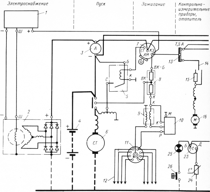
Rice. 1. circuit diagram electrical equipment of the ZIL-130 car: 1 - relay-regulator, 2 - generator, 3 - ammeter, 4 - battery, 5 - starter relay, 6 - ST130-A1 starter, 7 - ignition switch, 8 - additional resistance, 9 - coil ignition switch, 10 - transistor switch, 11 - distributor, 12 - spark plug, 13 - bimetallic fuse block, 14 - heater motor switch, 15 - heater motor resistance, 16 - heater motor, 17 - relay-interrupter of direction indicators, 18 - lamp control lamp, 19 - indicator lamp for emergency water overheating, 20 - temperature sensor, 21 - fuel level indicator, 22 - fuel level indicator sensor, 23 - water temperature indicator, 24 - water temperature indicator sensor, 25 - emergency drop indicator lamp oil pressure, 26 - pressure gauge contact, 27 - direction indicator switch, 28 - brake light switch, 29, 30 - rear lights, 31 sidelight, 32 - headlight, 33 - light switch, 34 - underhood lamp, 35 - ceiling light switch , 36 - cover, 37 - foot light switch, 38 - headlight high beam control lamp socket, 39 - instrument lighting lamp holders, 40 - bimetallic fuse, 41 - plug socket, 42 - sound signal, 43 - sound signal button (included in steering column kit), 44 - plug socket, 45 - turn signal repeater lamp
The ignition and start circuits are not protected against short circuits so as not to reduce their reliability in operation.
Thermal fuses are divided into multiple and single action fuses. When an overload or short circuit occurs in the circuit, the contact of the multiple blow fuse pulsates, turning the circuit on and off. The contacts of the single-acting fuse open in these cases. Turn on the fuse (close the contacts) by pressing the button.
Fusible fuse links are replaced after the elimination of the causes that caused short circuit. When replacing a fusible insert, only wire of the appropriate section is used. For example, with a maximum fuse current of 10 A, the tinned copper wire of the fusible link should have a diameter of 0.26 mm (for 15 A, respectively, 0.37 mm). It is strictly forbidden to use thicker wire (“bugs”) or factory fuses designed for a higher rated current.
In order to prevent electrical wiring malfunctions, it is recommended:
- periodically clean the wires, screw and plug terminals from dirt and moisture;
- pay special attention to the condition of screw and plug connections, preventing their corrosion, oxidation and loosening of connections. To prevent oxidation of the contact surfaces of the joints, lithol lubricant, etc. is used;
- regularly check the voltage drop in the circuit sections and contact connections of the main consumers of electricity.
Most of the malfunctions of the electrical equipment of cars occur due to untimely and poor quality Maintenance.
The main malfunctions in the on-board network are:
- break in the chain of sources and consumers electrical energy;
- excessive voltage drop in the circuit of sources and consumers of electrical energy;
- short circuit of wires and insulated parts and assemblies of devices to the body (ground) of the car.
It is advisable to start the search for the cause of the malfunction by checking by hand the reliability of fastening the wire lugs on the terminals of electrical devices, because a significant part of the malfunctions in the electrical system occurs when these lugs are loosened. At the same time, the resistance in the circuit increases, the temperature of the terminals increases, and when the car moves, due to vibration, the contact in the circuit is even broken.
An open in the circuit of sources and consumers of electrical energy occurs due to the melting of a fuse, opening of contacts in a thermal bimetallic fuse, rupture of wires, loose fastening of wire tips on the terminals, contact failure in the plug-in connection of wires, contact failure in switches and switches, open circuit in consumers (burnout filaments in the lamp, burnout of an additional resistor or motor winding, etc.).
In connection with wide application electronics on cars, fuses are widely used, which are installed in separate pads or blocks. When troubleshooting a circuit, it is convenient to use diagrams and tables with a list of consumers protected by numbered fuses (tables are given in the car's factory operating instructions). In order to make sure that the fuse is working, it is necessary to turn on the consumers protected by this fuse in turn. If at least one consumer works, the fuse is good.
If a fuse insert has melted, before replacing it with a new one, it is necessary to eliminate the malfunction that caused the fuse insert to melt. If there is no spare insert, you can solder the insert to the contacts copper wire with a diameter of 0.18 mm for a current of 6 A, 0.23 mm - for 8 A; 0.26 mm - at 10 A, 0.34 mm - at 16 A, 0.36 mm - at 20 A.
Before installing a new insert, it is necessary to bend the holder terminals, which will ensure reliable contact between the insert and the holder. Using the example of a simple circuit of the electrical equipment of a GAZ-bZA car, we will consider the search for wire breaks and other malfunctions of the on-board network (Fig. 2). For example, headlights do not light up.
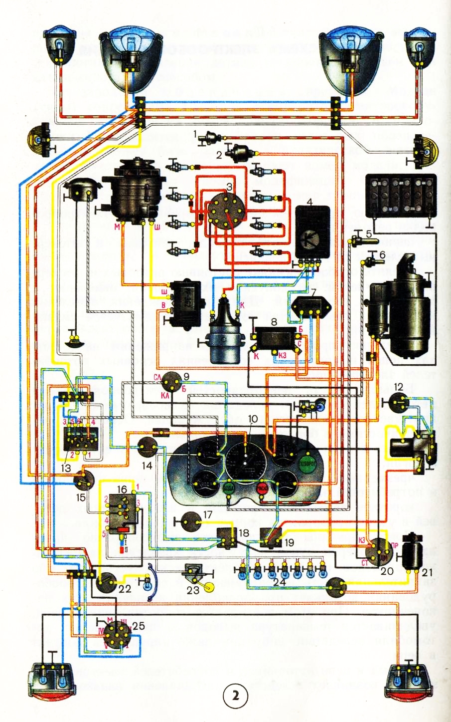
Rice. 2. Scheme of the electrical equipment of the GAZ-63A car: 1 - sensor of the emergency oil pressure warning lamp; 2- gauge indicator of the oil pressure gauge in the lubrication system; 3- breaker-distributor; 4 - transistor switch; 5 - engine overheat indicator sensor; 6 - engine coolant temperature indicator sensor; 7 - additional resistors; 8- starter enable relay; 9- interrupter of direction indicators; 10 - control lamp for switching on the high beam of headlights; 11 - engine compartment lamp; 12 - wiper motor switch; 13-switch of direction indicators; 14 - stoplight switch; 15 - foot light switch; 16 - central light switch; 17-pin socket for portable lamp; 18, 19 - thermobimetallic fuses; 20-ignition switch; 21 - heater motor; 22 - ceiling lamp switch; 23 - fuel level sensor; 24 - lighting lamps for instrumentation; 25 - trailer socket
Consider the current path in the headlight circuit. Positive battery terminal - starter traction relay terminal - ammeter - ignition switch terminal "AM" 20 - fuse 18-terminal "1" of the main light switch 16 - terminal "4" of the switch 16 - light foot switch terminal 15 - output terminal of the foot switch ( one of two, depending on the position of the switch) - terminal of the connecting panel (blocks) - filament of headlight bulbs - car body - negative terminal of the battery.
To determine an open in this circuit, connect one wire from a test lamp * or a voltmeter to the car body, and with the end of the other wire touch the terminals of consumers, devices, switches and connecting panels in turn, included in this circuit, starting from the positive terminal of the battery, in the sequence considered current paths. Before connecting a test lamp to terminal "4" of the main light switch, you must set the switch handle to position II. When connecting a control lamp to the output of the foot switch, press its stem 2-3 times.
When the test lamp goes out (or the voltmeter needle deviates to zero), this will indicate that the circuit has an open in the area from the previous point where the wire of the test lamp (voltmeter) touched to this point in the circuit under test.
A wire break can be determined in another way. To do this, disconnect the ends of the wire under test and connect it in series with a lamp (or voltmeter) to the battery. If there is a break, the control lamp will not light.
If necessary, check the serviceability of the lamps without removing them from the headlights. To do this, the positive terminal of the battery is connected with a conductor to the corresponding terminal of the connecting panel, to which the conductors from the tested lamps are connected. A good lamp will light up.
With a working lamp in the headlight, it, like the control one, will burn with incomplete heat. The control lamp burns with full heat in the event of a short circuit to the body of the electrical circuit in the headlight.
Attention!
It is strictly forbidden to check the health of the circuits of the consumers of the electrical energy of the car "for a spark", i.e., by shorting the wire to the case, since even a short-term short circuit can cause damage to the semiconductor devices of electrical equipment, printed circuit boards mounting blocks, etc.
An unacceptable voltage drop in consumer circuits is created due to an increase in resistance at the points of fastening of wire lugs on the terminals of sources and consumers of electrical energy, devices, connecting panels, as well as in the plug-in connection of conductors. The resistance increases due to the oxidation of the contacting surfaces of the parts, as well as the violation of the strength of the fastening of the wire lugs.
For example, when the terminals of the battery and the tips of the starter wires are oxidized, at the battery terminals, due to a sharp increase in resistance in the circuit, even if the starter and battery are in good condition, the current in the circuit is significantly reduced, and therefore the torque on the starter drive gear and the armature speed are reduced. . As a result, the starting speed of the engine crankshaft is not provided and it does not start.
Another example. In the event of a contact failure in the wire connection at the terminals, oxidation or loose contacts in the light switches, the lamps do not light or significantly reduce the light intensity. Similar phenomena are created in other circuits of the vehicle's on-board network. As a rule, in places where the wires are loose, heat increases, which is a sign of this malfunction. An increase in the temperature of parts accelerates their oxidation. The voltage drop in volts in various circuits of consumers of electrical energy is determined as follows. First, the voltage is measured at the battery terminals, then, for example, at the terminals of the connecting panels in the lighting and light signaling circuit. The voltage difference at the source and at the terminals of the connecting panels will be the magnitude of the voltage drop in the circuit under study.
The permissible voltage drop in the electrical circuit of headlights, sidelights, direction indicators, light signal lamps should not exceed 0.9 V for a 12-volt system and 0.6 V for a 24-volt system. The voltage drop should not exceed 0.1 V at each riveting of the wire lugs.
The short circuit of conductors and parts of apparatuses and devices of electrical equipment on the body of the car occurs due to the destruction of the insulation during mechanical or thermal damage to it. Since the conductors connecting sources and consumers of electrical energy have very low resistance, when they are closed to the car body, a high current will flow through them, as a result of which the fuse will open the circuit. If it is not protected by a fuse, then the insulation is destroyed and the conductors melt and the ammeter is thermally damaged. This may cause a fire.
To determine the short circuit of the wire to the car body, it is necessary to disconnect the ends of the wire under test from the terminals and connect one end in series with a lamp or voltmeter to the positive terminal of the battery. If there is a short to the body, the lamp will glow (dim or bright, depending on the degree of short circuit), and the voltmeter needle will show the voltage at the battery terminals.
Failure in the operation of electrical energy consumers connected to a group thermal bimetallic fuse most often occurs due to the opening of its contacts when this circuit is closed to the car body. To check, press the button of this fuse, and if its contacts open again, then there is a short circuit to the car body in the circuit of connected consumers. In this case, turn off the consumers, press the fuse button, and then turn on the consumers one by one. Serviceable consumers will work. If, when any consumer is turned on, the fuse contacts open, then there is a short circuit to the case in the circuit of this consumer.
On many modern cars, a mounting block is installed in the on-board network, in which all the fuses and most of the various relays are mounted. On fig. 3 shows the mounting block 17.3722 of a VAZ-2108 car, in which fuses (Pr1 - Pr16) and relays (K1 -KN) are installed. There are also resistors R1 and R2, diodes D1 and D2 of the KD215A type, diodes DZ, D4 and D5 of the KD105B type. The block has 11 plug-in blocks (Sh1-Sh11) for connecting bundles of wires.
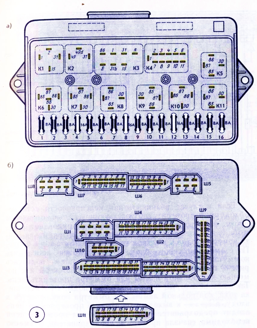
Rice. 3. Mounting block of fuses and relays 17.3722 of a VAZ-2108 car:
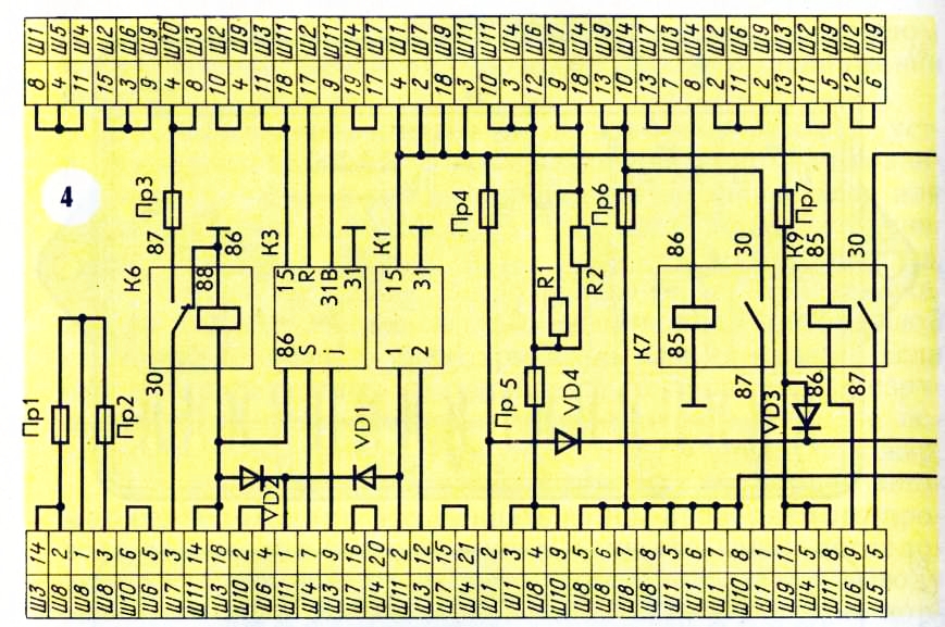
Rice. 4. Diagram of internal connections
If, in the event of a malfunction, there is a need to check the corresponding circuit in the mounting block, it is necessary to general scheme electrical equipment of the car or the power circuit of a faulty consumer, find the numbers of inputs and outputs of this circuit in the mounting block. According to the scheme of the mounting block (Fig. 4), it is possible to trace the switching of this circuit inside the block. Then, using Fig. 3, b, find these pads and plugs on the block and check the circuit using a test lamp or an ohmmeter. Since diodes are included in some circuits, the “+” of the current source, test lamp or ohmmeter is connected to the input, and “-” to the output of the circuit. If the circuit under test includes a fuse or relay, then to check the circuit, you must first check the fuse, and install jumpers instead of the relay: one instead of the contacts and the other instead of the coil.
The entry, for example, Ш1-2 means: plug block No. 1, output No. 2. The entry K1.15-K11 in the "Contacts ..." column means that you need to connect the plugs "15" and "1" of the relay socket K1 with a jumper. Jumpers can also be installed instead of a faulty relay.
For example, you need to check the brake light circuit on a VAZ-2108 car. Having found the brake light switch on the general electrical circuit, we see that two wires are suitable for it: white and red (magenta). The first of them is included in the block Ш4, the second - in the block Ш2.
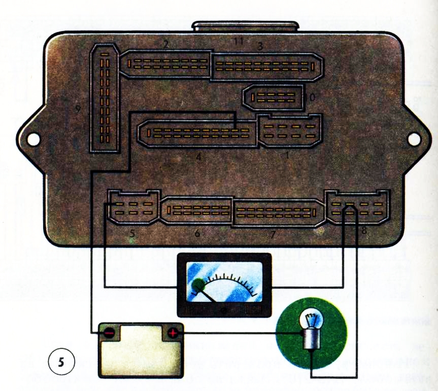
Rice. 5. Checking the mounting block of the test lamp and an ohmmeter
In the same place or according to separate wiring diagrams, usually given in repair manuals, we see that the white wire is connected to terminal No. 10, and the red wire to No. 3. According to the switching circuit of the mounting block, also available in the repair manuals, we find that power is supplied from the output Ш4-10 and it, in turn, is connected through the Prb fuse to the closed outputs Ш8-5, Ш8-6 and Ш8-7, two of which are used to supply power from the generator (battery). In the same place we find that through the output Ш2-3 and further Ш9-14 current is supplied to the lamps in the rear lights.
If the fuse is in good condition (usually you need to make sure of this right away, using the fuse table located, for example, in the “Car Operation Manual”), we connect a test lamp (Fig. 5) to terminals Ш4-10 and Ш8-7 (Ш8-5, Ш8-6). Similarly, we check the circuit of the mounting block between the terminals 1JJ2-3 and Ш9-14. If there is an open circuit in the circuit, you need to disassemble the unit and solder the broken section of the board (you can solder the conductor parallel to it) or replace the printed circuit boards.
Another example: you need to check the dipped beam circuit of the right VAZ-2108 headlight in the mounting block. According to the table of fuses, we find that the low beam thread of this headlight is protected by a Pr 16 fuse. In fig. 4 it can be seen that this fuse, on the one hand, has an output to sh5-6 and sh7-4 (empty), and on the other hand, it is connected through the contacts of the KN relay with power (pins Sh8-7, Sh8-5, Shch8-6, as and in the previous example). In turn, the KP relay coil is connected to the Sh4-12 output (to the steering column-left light switch) and the mass of the unit - the ShZ-5 and Sh10-5 outputs.
To check these circuits, instead of the relay, we put two jumpers: 30-87; 85-86. Then we connect an ohmmeter to the conclusions Ш8-7 (Ш8-5, Ш8-6) and Ш5-6. The resistance should be close to zero. Similarly, we connect an ohmmeter to the conclusions Ш4-12 and ШЗ-5 (Ш10-5).
Obviously, the use of a control lamp in the first example, and an ohmmeter in the second, is equivalent.
On a car, to check the health of the relay, for example, K11, it can be replaced with a similar one, for example K5. If, after replacing the relay, the headlights turn on, then the unit is OK, and the replaced relay is faulty. Instead of a faulty relay, you can leave a jumper, but keep in mind that in this case the contacts of the headlight switch will be overloaded, which will cause them to oxidize. Detailed testing of various relays is described in the relevant sections of the book.
TO Category: - 1Domestic cars
A modern car has a complex electronic “stuffing”, which is called in one general word “electrical equipment”. Vehicle electrical equipment- these are its lighting devices, engine start mechanism, car security, heater and air conditioning, etc. Electricity is generated from sources (battery and generator) and transmitted to consumers.
Current consumers in the electrical system of a passenger car are: an engine start system, a car ignition system, a lighting and alarm system, instrumentation and additional equipment, which may differ for each car.
We have already met with the engine ignition system earlier (see Chapter 2, section "Ignition System"). We only recall that for the operation of an internal combustion engine, a spark plug is needed, which gives an electric spark, from which the working mixture in the cylinder ignites (glow plugs are used in diesel engines). And this spark appears due to the presence of an electrical system in the car. We will get acquainted with other consumers of electricity in this chapter. In other words, next we will learn about how the electrical energy of a modern car is generated and used.
Sources of electric current
The electric current in the car is generated from two sources: the battery (accumulator) and the generator.
Battery task(Fig. 4.1) - provide electricity to the appropriate vehicle equipment when the engine is off, as well as when the engine is running at low speeds. The battery is usually located in the engine compartment on a special metal shelf, but in some car models it can also be installed in the passenger compartment.
The battery has "plus" and "minus" on the corresponding poles. The negative pole is connected to the car body and provides, as the drivers say, "ground". The positive terminal is connected to the electrical circuit of the car, through which electricity is transmitted.
The battery includes six separate batteries located in one housing and connected in series to form a single battery. electrical network. Electrochemical processes take place in each battery, as a result of which a current of 2 volts is obtained. It is easy to calculate that in total, a direct current of 12 volts is formed on the poles of the battery (six batteries of two volts each).
The battery is marked with the standard pattern. For example, marking 6ST-60A stands for:
6 - the number of batteries in the battery (for all cars, this figure is unchanged);
ST - type of battery, in this case - starter, which allows you to start the engine with the help of a powerful consumer of electricity (starter);
60 - battery capacity, which is measured in ampere-hours (in this example, 60 ampere-hours);
A is the designation of the material from which the battery case is made (in this example, polypropylene).
The more power required to start the engine, the more capacity the battery must have. For standard Soviet Zhiguli, batteries with a capacity of 55 ampere-hours were used. But such a battery may not be enough to start diesel engines - they need at least 60-65 ampere-hours.
Usually new battery serves for 6-7 years. After that, it must be replaced, although sometimes you can extend its life by periodically recharging it with a special charger.
Generator(Fig. 4.2) is the source electric current, providing electricity to all consumers when the engine is running at high and medium speeds. In addition, the most important function of the generator is to recharge the battery (also with the engine running). Without a generator, a new battery will be discharged very quickly and its use will become impossible.
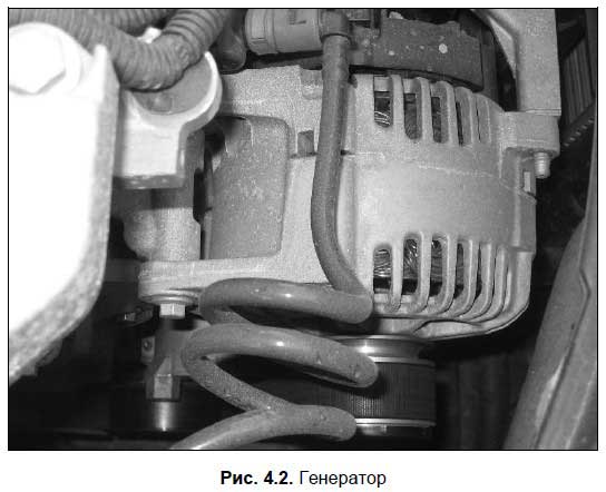
In the electrical circuit of the car, the generator is connected in parallel with the battery. Therefore, it will supply consumers with electric current and charge the battery only when the voltage it generates is greater than the voltage supplied by the battery. This happens when the car's engine is running at a speed above idle: after all, the voltage of the electric current that is produced by the generator directly depends on the speed of rotation of the generator rotor, which is driven by the engine.
It should be noted that sometimes the voltage generated by the electric current generator may be greater than necessary. To prevent this situation in the car, a special device called a voltage regulator is used. This device operates in tandem with a generator, limiting the voltage of the current it produces and regulating it in the region of 13.6-14.2 volts. The voltage regulator can be built into the generator, or it can be located in the engine compartment separately from the generator.
There is a specially designed bracket for mounting the generator on the engine. The generator is driven by the engine crankshaft through a belt drive. On many machines, with the help of one belt, a drive is created from the crankshaft to the generator, the constantly running fan and the water pump (pump), i.e., all these units work as if in one bundle, although they perform completely different functions. However, this is not necessary - often the generator has a separate drive belt. In any case, it is necessary to periodically check the belt tension and, if necessary, adjust it by tilting the generator housing. Remember that an insufficiently tensioned belt, firstly, makes unpleasant whistling and creaking sounds during operation, and secondly, it quickly fails.
On the instrument panel of any car, there is always a red battery charge light. It always lights up when the ignition is turned on and goes out after starting the engine. If, when the engine is running, the light does not go out, this indicates problems in the power supply system (probably the generator has failed).
Lighting and signaling devices
Lighting devices are designed to indicate the dimensions of the vehicle when driving at night and in conditions of insufficient visibility, as well as to illuminate the road and the interior of the car (engine compartment, passenger compartment, trunk). Lighting devices are headlights (block headlights), license plate lamps, interior lamps, trunk lamp, engine compartment (engine compartment) lamp and taillights.
Block headlight (Fig. 4.3) consists of a body, diffuser and reflector. Inside the housing there is a lamp inserted into the socket, which can operate in two modes: low beam headlights and high beam headlights. The dipped or main beam is switched on using a switch located in the passenger compartment. There is also a light bulb inside the headlight. side light, which is designed to indicate the dimensions of the car, if necessary (there is also a toggle switch to turn on the dimensions).
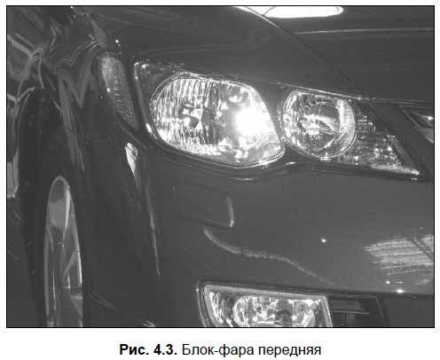
Modern block headlights often also contain a turn signal bulb, but it can also be located separately - it all depends on the specific car model.
Rear lights (Fig. 4.4) in modern cars are also usually made in the same housing.
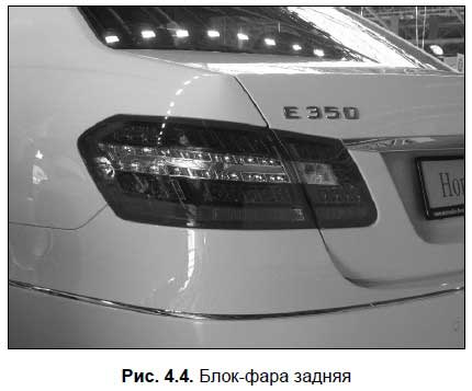
Rear light includes:
Stop lamps (turn on automatically when the driver presses the brake pedal, and turn off when the pedal is released);
Reversing lamps (light up automatically when the driver turns on the reverse gear, and go out when it is turned off);
direction indicators;
Parking lights.
The driver turns the direction indicators on and off using a special switch, which is usually located on the steering column. All direction indicators simultaneously work when the driver turns on the alarm (a special button is designed for this). The procedure for the use of emergency light signaling is regulated by the current traffic rules.
An audible signal is a signaling device designed to audibly alert other road users of imminent danger. It is activated by pressing a special button or key, usually located on the steering wheel. The procedure for applying the sound signal is prescribed in the traffic rules.
Engine start system
To turn on the engine, the engine start system is designed, consisting of an ignition switch, a starter with a traction relay, a starter drive mechanism and a starter enable relay.
The engine is started using starter(Fig. 4.5).
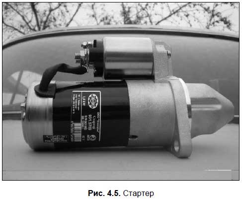
This device is a DC electric motor. When the driver turns the key in the ignition switch to the "Start" position, the electric current through the relay is supplied from the battery to the starter windings. As a result, the traction relay is activated, the special starter gear engages with the engine flywheel and turns it. Since the ignition is already on, the engine will start and run.
Note that the starter is used solely to start the engine; the rest of the time this device "rests". The process of the starter can be divided into three key stages.
First, a special gear located on the starter armature shaft engages with the engine flywheel ring gear (this is possible due to the drive mechanism). Visually, this can be represented as follows: take two gears, one of which will illustrate the flywheel ring gear and the other the starter gear, and engage them. If you turn the “starter gear”, then the “flywheel ring gear” will certainly turn.
Next, the starter shaft, together with the gear engaged with the flywheel, begins to rotate, as a result of which the flywheel rotates, and therefore the engine crankshaft also rotates, after which it starts.
Then, when the driver has started the engine and released the key in the ignition, turning off the starter (the key in the “Start” position can only be held by force, since it automatically returns back), the starter gear disengages to the side (the gear teeth will remain at the same level, but only to the side). It is in this position at all times when the engine is running or off, and engages with the flywheel only when the driver turns the ignition key to the "Start" position.
Remember this.
Immediately after starting the engine, turn off the starter by releasing the key in the ignition. Forcibly holding the key while the engine is running in the “Start” position can quickly disable the starter: a heavy rotating flywheel rim will at least simply “grind” the starter gear. It is possible that the starter will receive other damage (the traction relay will burn out, etc.). For the same reason, in no case should the starter be turned on while the engine is running.
With proper use, the starter is a fairly reliable device that can serve throughout the entire life of the car.
Instrumentation
To promptly inform the driver about the condition of important components and assemblies of the car, the current speed limit, the availability of fuel, the distance traveled and other important factors in the car, instrumentation(abbreviated KIP). The instrumentation is located in a place convenient for the driver's view, namely, on the instrument panel (instrument panel), located immediately behind the steering wheel (Fig. 4.6).
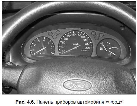
A typical instrument panel contains control lamps, an odometer (a mileage counter, and separately for total and daily mileage), a coolant temperature sensor, a speedometer, a fuel level sensor and an engine speed indicator (tachometer). Also, the instrument panel may include other instrumentation - it depends on the car model.
Everyone should know this.
Valid for all KIP general rule: when the engine is running, in no case is it allowed to glow any red light (indicator) or find the arrow of any indicator in the red sector. Such indications of the instrumentation inform the driver about the presence of serious malfunctions in the corresponding unit, and the vehicle cannot be operated until they are eliminated.
Indicator lamps provide the driver with information about the current state of systems, components and assemblies. In particular, when the ignition is turned on, the red lamps for battery charging and oil pressure light up - they should go out after starting the engine. If the car is on the "handbrake", then on the instrument panel with the ignition on, the corresponding red light will light up, which will go out only after the parking brake system is turned off.
When you turn on the dipped or main beam headlights, the lamps on the instrument panel light up, respectively, green and blue flowers. When the driver turns on the direction indicator or emergency gang, the corresponding indicator flashes on the instrument panel, which is accompanied by characteristic audible clicks.
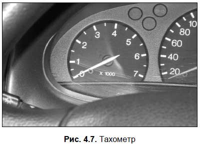
Tachometer(Fig. 4.7) shows how many revolutions per minute the engine crankshaft makes in the current mode of operation. Usually it is measured in thousands, so the dial contains the numbers 1, 2, 3, etc., and when the hand points to a number, you should multiply it by 1000.
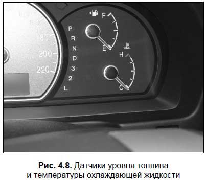
Fuel level sensor(Fig. 4.8) informs the driver about the amount of fuel available in fuel tank At the moment. When there is too little fuel left, the arrow approaches the red sector, and in many cars, the corresponding lamp lights up additionally (sometimes it looks like a gas station). Do not ignore the alarm readings of the sensor - otherwise you risk stalling on the road due to lack of fuel in the fuel tank.
Odometer shows the number of kilometers traveled by the car, and in modern cars separate meters are designed for the total and for the daily (or for any arbitrary time interval) run.
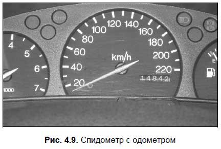
Speedometer(Fig. 4.9) is a device that informs the driver about the current speed mode (in other words, at what speed the car is currently moving). The indications of this device are extremely important for choosing the correct speed and for preventing violation of the speed limit established on this section of the road by the current Rules of the Road.
coolant temperature sensor(see Fig. 4.8) informs the driver whether the engine cooling system is functioning properly. We have previously said that the operating temperature of the coolant should be between 80-90 degrees Celsius. If the sensor arrow has moved to the red sector, it means that the liquid temperature is approaching 100 degrees or has already reached it. In such a situation, immediately turn off the engine and let it cool down.
Additional equipment of a modern car
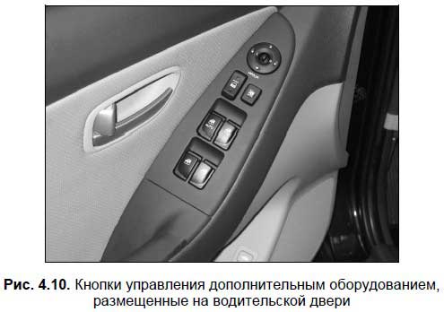
Additional vehicle equipment is intended mainly to improve the comfort and convenience of the trip, as well as to provide the necessary driving conditions. Among the most common types additional equipment It can be noted: interior heater, air conditioning, radio, windshield wiper and washer, glass, mirror and seat heating devices, electric window and seat lifts, electric headlight corrector, headlight cleaner and washer, refrigerator, satellite alarm system, etc.
The interior heater is simply called a “stove”, without it in most Russian regions you can operate a car for no more than three to four months (otherwise you can just freeze). Also, the heater is used for blowing windows, eliminating the condensate that has appeared on them (the so-called "fogging"). When a car engine overheats, turning on the stove at full power sometimes helps.
The windshield wiper and washer provide visibility when driving in rain or snow, or when driving on muddy roads.
Please note.
Traffic rules prohibit the operation of a vehicle if it does not have windshield wipers and washers designed for it.
Not all cars are equipped with a glass and mirror heating system (this does not apply to the rear window - it is heated in all modern cars). These devices help to quickly remove ice and snow from car windows and mirrors. Not all cars also have a seat heating system, but if it is, then getting into a cold car in winter will be much more pleasant.
Also a popular device is air conditioning. In hot weather, this device is able to turn a tiring ride in a car under the scorching sun into a real pleasure. The presence of an air conditioner is of particular importance for people who are prone to motion sickness when driving in a car (for example, the elderly or children). On the other hand, use the air conditioner with caution, as there is a high risk of catching a cold.
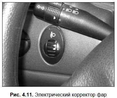
Electric headlight corrector (Fig. 4.11) have many modern foreign cars. This device allows the driver from his seat to adjust the direction of the headlights - higher or lower.
A headlight wiper and washer are not devices that every modern car should be equipped with (unlike a windshield wiper and washer). But when driving on dirty roads, these devices are very convenient, because they allow you to clean the headlights of dirt while driving.
Ministry of Education Russian Federation
Saint Petersburg State University
service and economy
Essay
Topic: "Electrical equipment of cars"
Fulfilled
3rd year student
Specialty 100.101
Ivanov V.I.
Saint Petersburg
Introduction
1. Current sources
1.1 Generator
1.2 Voltage regulator
1.3 Battery
2. Current consumers
2.1 Starter
2.2 Ignition system
2.3 Designs of devices of the ignition system
2.4 Lighting system
2.5 Alarm system
2.6 Instrumentation
List of used literature
Introduction
The electrical equipment of the car is a set of electrical appliances and equipment that ensures the normal operation of the car.
In a car, electrical energy is used to start the engine, ignite the working mixture, lighting, signaling, power control devices, additional equipment, etc. The electrical equipment of the car includes sources and consumers of current. A single-wire system is used to connect current sources and consumers. The second wire is the mass of the car (its metal parts), to which the negative poles of electrical appliances are connected. feed on electrical devices DC voltage 12 or 24 V (vehicles with diesel engines).
1. Current sources
Power sources provide electricity to all consumers of the car. The sources of current in the car are the generator and the battery. Current sources also include devices for their regulation. A simplified diagram of the general electrical system of the vehicle's electrical equipment and the connection of devices without taking into account their actual location on the vehicle is shown in fig. 1.
Rice. 1. Schematic simplified diagram of the electrical equipment of the car:
1 - accumulator battery; 2 - starter; 3 – ignition system devices; 4 - lighting system devices; 5 - alarm system devices; 6 - control electrical appliances; 7 - additional equipment; 8 - generator; 9 - voltage regulator
1.1 Generator
Generator converts mechanical energy received from the engine, into electrical. The generator feeds all consumers of electric current and charges the battery when the engine is running. Alternators are used on cars, which are a three-phase synchronous electric car with electromagnetic excitation.
On fig. 2 shows an alternator. The main parts of the generator are the stator 8 with a fixed winding, in which an alternating current is induced, and a rotor 7, which creates a moving magnetic field.
The generator rotor is mounted in two ball bearings 5. It is driven by a pulley 4 alternator using a V-belt from the engine crankshaft. This belt also rotates the fan drive pulley and coolant pump. During the operation of the generator, a current flows through the excitation winding of the rotor, which is supplied through the brushes 3 and creating a magnetic field, which, when the rotor rotates, induces an alternating current in the stator winding.
Alternating current converted to DC by rectifier unit 2 generator is cooled by pulley fan 4 generator. The generator is mounted on the engine block. It attaches to the cast iron block bracket and tension bar. In the ears of the lids 1 And 6 generator for fastening rubber buffer bushings are used 9, providing an elastic connection and excluding breakage of the ears.
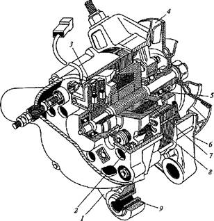
Rice. 2. Generator:
1, 6 – covers; 2- rectifier block; 3- brushes; 4- pulley; 5- bearing; 7- rotor; 8- stator; 9 - sleeve
1.2 Voltage regulator
The voltage regulator maintains a constant voltage generated by the generator at a variable engine speed. The voltage regulator (Fig. 3) is a two-stage electromagnetic vibration type regulator. When the generator voltage increases to 13 ... 14 V, the armature 6 of the regulator is under the action magnetic field windings 8 and spring 7 begins to vibrate, opening and closing the movable 4 and top fixed 5 pins. At the same time, additional resistance 1 is switched on and off from it in the excitation winding circuit of the generator. This is how the first stage of generator voltage regulation is carried out. When the generator voltage rises more than 14 V, the movable 4 and bottom fixed 5 pins. When these contacts are closed, the excitation winding of the generator closes to ground. This is how the second stage of generator voltage regulation occurs. As a result, the voltage generated by the generator is regulated within the specified limits. To reduce sparking between contacts 4 And 5 during the operation of the regulator, a throttle is used 2. The voltage regulator is closed from above with a steel cover with a polyurethane gasket and is installed in the engine compartment under the hood.
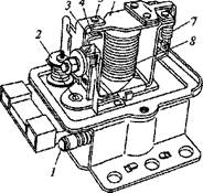
Rice. 3. Voltage regulator: 1 - resistance; 2 - throttle; 3,4,5- contacts; 6 - anchor; 7- spring; 8 - winding
Constant pressure current generated by other generators can also be supported by a small-sized microelectronic voltage regulator, which is built into the generators. It is a non-separable and unregulated device. When the generator voltage rises above 13.5-14.5 V, the voltage regulator interrupts the flow of current to the rotor excitation winding. As a result, the generator voltage drops. The voltage regulator again passes current into the excitation winding of the rotor, I the process is repeated. Thus, by continuously and automatically adjusting the current passing through the excitation winding of the generator, the regulator maintains the generator voltage within 13.5 ... 14.5 V, regardless of the load current and engine speed.
1.3 Battery
The battery converts chemical energy into electrical energy.
The battery on the car feeds consumers of electric current when the engine is idle or running at a low crankshaft speed. Lead-acid batteries are used in automobiles. internal resistance and capable of delivering a current of several hundred amperes for several seconds, which is necessary to start the engine with a starter.
The battery is characterized by capacity, i.e. the amount of electrical energy that a battery can give when discharging from a fully charged state to the maximum allowable discharged state.
The battery capacity is measured in ampere-hours and depends on its design, the number of plates, their thickness, the material of the plate separators and other factors.
In operation, the capacity of the battery depends on the strength of the discharge current, the temperature of the electrolyte, the discharge mode (intermittent or continuous), the degree of charge and deterioration of the battery. So, with an increase in the discharge current and a decrease in the temperature of the electrolyte, the capacity of the battery decreases.
Frame 1 battery (Fig. 4) is made of acid-resistant plastic (polypropylene) and is divided into six sections by partitions. Each section has a separate element, consisting of positive 9, negative 10 plates and separators 8 (separators) between them. The elements have a voltage of 2 V and are connected in series with each other by bridges. 4. The battery case is closed with a plastic cover common to all elements. 2. Cover Welded along the periphery to the outer walls of the housing. The connections of the cover with the partitions of the body are sealed during assembly with a sealant, which eliminates the overflow of electrolyte from one section to another. For each section in the cover there is a threaded hole with a plug 6 for filling and control with an electrolyte level indicator 7. The plugs are provided with holes for connecting the internal cavity of the battery with the atmosphere. The battery has two terminals: positive 3 and negative 5. The battery is installed in the engine compartment under the hood.
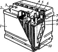
Rice. 4. Battery:
1 - frame; 2- lid; 3, 5- conclusions; 4 - bridge; 6 - cork; 7 - indicator; 8 - separator; 9, 10 - plates.
Batteries are marked. The battery marking indicates: the number of cells connected in series, which determines the battery voltage; purpose of the battery; battery capacity in ampere-hours at a discharge mode of 20 h, the material of the battery case and the material of the separators. For example, the designation of the battery 6ST-55P means the following: starter battery, voltage 12 V, capacity 55 Ah, case and cover made of propylene (acid-resistant plastic).
When servicing the battery, you must follow the safety rules: handle electrolyte containing chemically pure sulfuric acid; when examining the battery, it is impossible to bring open fire to it because of the possibility of a flash of gases over the electrolyte, etc.
2. Current consumers
Current consumers on a car are a starter, an ignition system, a lighting system (external and internal), an alarm system (sound and light), control electrical appliances and additional equipment.
2.1 Starter
The starter motor rotates the crankshaft at the required frequency to start the engine. The starting speed of the crankshaft of gasoline engines is 40 ... 50 min -1. The starter is a four-pole, four-brush mixed-excitation DC motor with electromagnetic engagement of the drive gear and remote control.
in steel case 11 starter (fig. 5) four poles are fixed 12 with excitation windings, three of which are connected to the armature winding 13 in series and one in parallel.
The starter armature shaft rotates in two bushings 8 from sintered materials impregnated with oil. The bushing of the rear end of the shaft is pressed into the cover P, and the bushing of the front end of the shaft is pressed into the clutch housing. At the front end of the armature shaft is the starter drive, which includes a freewheel. 2 and gear 1 drive, which, when the starter is turned on, move along the splines of the shaft. Starter covers are cast from aluminum alloy. On the front cover 4 traction relay fixed 5, tied with a plastic lever 3 and ring 14 with starter drive. The relay ensures that the gear engages with the flywheel ring and connects the electric circuit of the starter windings to the battery when the engine is started. On the back cover 9 brush holders with four copper-graphite brushes 7 are installed. The brushes are pressed against the end collector by springs 6 anchors. The end collector is made in the form of a plastic disk, in which copper contact plates are poured. Such a collector reduces the length of the starter, reduces its mass and contributes to a more stable and durable operation of the brush contacts. The covers and starter housing are held together by two bolts. 10. freewheel clutch 2 consists of outer 16 and internal 1 5 clips. The inner race is integrated with the starter drive gear. The outer cage is combined with the hub, which is connected to the armature shaft through spiral splines. Spiral splines allow the clutch to rotate as it travels along the shaft, making it easier to engage the gear teeth 1 starter and flywheel ring. The outer cage has three slots of variable width in which the rollers are placed. 18 and clamping plungers 17 with springs. The rollers are constantly squeezed into the narrowed part of the cutouts, jamming the outer and inner clips. When starting the engine, the jamming of the clips increases, and after starting the clips wedged, since the rollers, overcoming the resistance of the springs of the clamping plungers, roll out into the expanded part of the grooves of the outer clutch clip. The starter is mounted on the left side of the engine and is attached with three studs and nuts to the clutch housing through the front cover flange. 4.
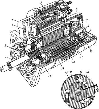
Fig.5. Starter:
1 - gear; 2 - clutch; 3 - lever arm; 4,9 - covers; 5 - relay; 6- collector; 7- brushes; 8 - sleeve; 10 - bolt; 11 - body; 12 - pole; 13 - anchor; 14 - ring; 15, 16 - clips; 17 - plunger; 18 - video clip
2.2 Ignition system
The ignition system is used to ignite the working mixture (combustible mixture mixed with exhaust gas residues) in the cylinders in accordance with the order and mode of operation of the engine.
On vehicles with gasoline engines, depending on their purpose and class, they are used various systems ignition (Fig. 6).

Rice. 6. Types of ignition systems
IN contact ignition system(Fig. 7, A) included: coil 6 ignition; distributor 1 ignition, consisting of a low voltage current interrupter and a current distributor high voltage; candles 3 ignition; wires 2 and 5 high voltage switches 4 ignition.
Scheme of the ignition system (Fig. 7, b) consists of two electrical circuits: a low voltage circuit (primary) and a high voltage circuit (secondary). Primary circuit includes ignition switch 4, additional resistance 17, primary winding 16 ignition coils 6, breaker 14 low voltage circuits and capacitor 13.
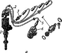
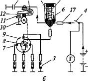
Rice. 7. Contact ignition system: a - device; b - scheme; 1,9- distributors; 2, 5 - wires; 3 - candle; 4 - switch; 6 - coil; 7, 11, 12 - contacts; 8 - rotor; 10 - cam; 13 -capacitor; 14 - breaker; 15, 16 - windings; 17 - resistance
The secondary circuit includes the secondary winding 15 ignition coils, distributor 9 high voltage and spark plugs. With the ignition switch on and contacts closed 11 And 12 low voltage circuit breaker, the primary circuit carries current from the battery or alternator. Passing through the primary winding of the ignition coil, the current creates a strong magnetic field. When opening the contacts of the breaker 14 (cam 10 runs with a ledge on the lever with contact 12) the current in the low voltage circuit is interrupted, the created magnetic field disappears. In this case, the magnetic field crosses the secondary winding of the ignition coil, and a high voltage current is induced in it. High voltage current is applied to the rotor 8 ignition distributor that rotates with the cam 10. At the moment of opening the contacts of the breaker, a high voltage current flows to one of the contacts / distributor of the ignition, which are connected to the spark plugs 3. The spark discharge between the electrodes of the spark plug occurs in the cylinder in which the compression of the working mixture ends at this time, i.e. in the sequence corresponding to the order of operation of the engine.
The contact ignition system does not provide reliable operation of car engines with an increase in the number of cylinders, compression ratio and maximum crankshaft speed. To ensure reliable operation of such engines, it is necessary to increase the current in the primary circuit of the ignition system (low voltage circuit), which is impossible due to a decrease in the life of the breaker contacts due to their burning.
Contact-transistor ignition system in comparison with the contact system, it provides more reliable operation of the engine, increases its service life and acceleration, facilitates starting, reduces fuel consumption, wear of spark plugs and breaker contacts. It increases the high voltage current by more than 25 %, as well as the energy and duration of the spark discharge (almost 2 times), which contributes to a more complete combustion of even a lean working mixture in the engine cylinders.
The contact-transistor ignition system includes: ignition coil; an ignition distributor including a low voltage current breaker and a high voltage current distributor; spark plug; transistor switch, high voltage wires and ignition switch.
The main feature of the contact-transistor ignition system (Fig. 8) is that the transistor switch 5, included in the primary circuit between the ignition coil and contacts 4 of the breaker, unloads the contacts. In this regard, there is no need for a spark-quenching capacitor. The system works as follows. When the ignition switch 4 is on, after closing the contacts 4 of the breaker, the switch transistor 5 opens, and current will flow through the primary winding 7 of the ignition coil. At the moment of opening the contacts of the breaker, the switch transistor is closed. The current in the primary circuit decreases sharply, and during secondary winding 6 ignition coils, a high voltage current is generated. It goes to the rotor 2 distributor 3 ignition, which distributes high voltage current to the spark plugs 1 ignition in accordance with the order of operation of the engine.
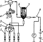
Rice. 8. Scheme of the contact-transistor ignition system:
1 - candle; 2 - rotor; 3 - distributor; 4 - contacts; 5 - switch; 6,7- windings; 8 - switch
Contactless ignition system ensures reliable operation of the engine, as it allows to obtain stable sparking in spark plugs and more stable ignition of the working mixture in various engine operating modes. The main feature of this ignition system is its non-contact sensor, which is not subject to mechanical wear. Therefore, the ignition timing does not change with increasing vehicle mileage in a contactless system and the system does not require maintenance during operation.
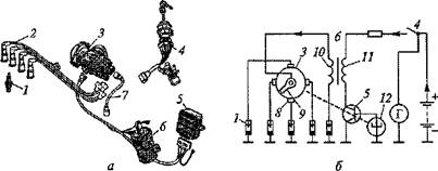
Rice. 9. Contactless ignition system:
A- device; b- scheme; 1 - candle; 2,1 - wires; 3 - distribution sensor; 4 - switch; 5 - switch; 6 - coil; 8 - contact; 9 - rotor; 10, 11 - windings; 12 - sensor
In a contactless ignition system (Fig. 9, A) included: coil 6 ignition; sensor - ignition distributor 3, consisting of a non-contact microelectronic sensor and a high voltage current distributor; candles 1 ignition; electronic switch 5; wires 2 and 7 high voltage switch 4 ignition.
A schematic diagram of a non-contact ignition system is shown in fig. 9, b.
With the ignition switch on 4 low voltage current is supplied to the electronic switch 5 and to the non-contact microelectronic sensor 12, located in the sensor - ignition distributor 3. The camshaft of the engine rotates the shaft of the distribution sensor, and the proximity sensor 12 delivers pulses to switch 5, which converts them into current pulses in the primary winding 11 ignition coils 6. The current passing through the primary winding of the ignition coil creates a magnetic field. At the moment of interruption of the current, the magnetic field is sharply reduced, and in the secondary winding 10 ignition coils, a high voltage current is induced. High voltage current flows to the rotating rotor 9 ignition distributor and from it to one of the contacts 8 distributor connected to spark plugs 1. A spark discharge between the electrodes of the spark plug ignites the mixture in the cylinders in accordance with the engine's firing order.
When servicing a non-contact high-energy electronic ignition system, do not touch the ignition system instruments with the Engine running and check their operation for a spark between the spark plug wire tips and the vehicle ground. This can lead to serious injury, damage to the ignition system instruments and failure of the system itself.
2.3 Designs of devices of the ignition system
The design of the ignition system devices requires more detailed consideration.
Ignition coil converts a low voltage current of 12 V into a high voltage current, which can reach 16 ... 20 kV in a contact ignition system and 20 ... 25 kV in a contact-transistor and non-contact ignition systems. The contact ignition system uses the ignition coil shown in fig. 10.
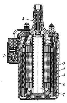
Rice. 10. Ignition coil:
1 - resistance; 2 - lid; 3 - frame; 4 - oil; 5, 6- windings; 7 - core
On the core 7 of the ignition coil, consisting of thin sheets electrical steel, wound secondary winding 6, which has a large number of turns (21000) of copper insulated wire with a diameter of 0.07 mm. The primary winding 5 has 308 turns of insulated copper wire with a diameter of 0.57 mm. Inner cavity of die-cast aluminum housing 3 filled with transformer oil 4, improving cooling and insulation of the ignition coil windings. In a plastic lid 2 coils have outputs of the primary and secondary windings. There is additional resistance outside the coil body 1, connected in series with the primary winding and automatically adjusting the current in the winding depending on the speed of the engine crankshaft. The ignition coil is located in the engine compartment under the hood. It is bolted to the car body.
A similar device has an ignition coil used in other ignition systems. The difference lies in the winding data (lower resistance primary winding and a greater number of turns in the secondary winding, etc.). In addition, the design provides for protection of the ignition coil from explosion in the event of a switch failure.
Distributor ensures the closing and opening of the low voltage current circuit and the distribution of high voltage current to the engine cylinders.
In the contact ignition system, an ignition distributor with centrifugal and vacuum ignition timing regulators is used (Fig. 11).
It consists of a breaker and a distributor installed in one common housing. 2, cast from aluminum alloy. Camshaft 7 is also installed in the distributor housing 18 interrupter, rotor 10 a distributor and a centrifugal regulator that automatically changes the ignition timing depending on the engine speed. When the shaft rotates 1 cam 18 opens contacts 20 breaker. The rotor rotates with the shaft 10 and centrifugal regulator. Weights 17 of the centrifugal regulator - ceramic-metal, mounted on axles on the base plate 9, which is connected with the cam 18 breaker. As the frequency of rotation of the ignition distributor shaft increases, under the action of centrifugal forces, the weights diverge, abut against the plate 16, overcome spring resistance 15 and rotate the breaker cam relative to the shaft, changing the ignition timing. Lid 12 ignition distributor has four side electrodes 11 and center electrode 13. The side electrodes are connected to the spark plugs, and the central electrode is connected to the ignition coil by high voltage wires, which have resistances distributed along the length to reduce radio interference created by the ignition system. High voltage current through the central electrode is supplied to the electrode 14 rotating rotor 10, consisting of resistance for suppression of radio interference, central and external contacts. From the rotor electrode, the current is supplied to the side electrodes 11 according to engine operation.
A capacitor is installed on the ignition distributor housing 3 and vacuum regulator 4. The capacitor protects the breaker contacts from burning and increases the high voltage current in the secondary winding of the ignition coil. It is connected in parallel with the breaker contacts. The vacuum regulator automatically changes the ignition timing depending on the load on the engine or the vacuum under the throttle valves of the carburetor. With an increase in the load on the engine in the cavity located between the diaphragm 5 and the cover 6 connected to the throttle body, the vacuum increases. The diaphragm, overcoming the resistance of the spring 7, bends and through the rod 8 rotates the movable plate 19 with contacts 20 relative to the cam 18 interrupter, while changing the ignition timing. The ignition distributor is mounted vertically at the left front of the engine, and its shaft is driven by a gear from the oil pump drive shaft, which in turn is driven by a chain drive from the engine crankshaft.
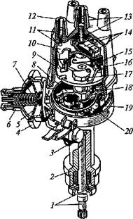
Rice. 11. Ignition distributor:
1 - shaft; 2 - frame; 3 - capacitor; 4 - regulator; 5 - diaphragm; 6, 12 - covers; 7, 15 - springs; 8 - thrust; 9, 16, 19 - plates; 10 - rotor; 11, 13, 14- electrodes; 17 - weight; 18- cam; 20 - contacts
A similar device has an ignition distributor of a contact-transistor system.
In a contactless ignition system, a sensor is used - an ignition distributor (Fig. 12), which supplies low voltage control pulses to the electronic switch and distributes high voltage pulses to the spark plugs.
Distributor sensor- four-spark, with vacuum and centrifugal ignition timing controls, has a built-in non-contact microelectronic sensor. In case 13 sensor-distributor, cast from an aluminum alloy, a shaft is installed 15 contactor drive 9, rotor 5 of the distributor and centrifugal regulator of the ignition timing. The shaft rotates in a sintered bushing and ball bearing which are impregnated with oil. Sleeve 17 is pressed into the housing of the sensor-distributor and sealed with a cuff 14, A spherical bearing 21 is installed in the holder 7 fixed in the housing 13. Bearing is also installed in the holder 22 moving plate 8, on which a non-contact microelectronic sensor is fixed 21, consisting of a permanent magnet, a semiconductor wafer and an integrated circuit. The sensor has a slot design. On one side of the slot is a sensitive element, and on the other side - a permanent magnet. In the sensor slot 21 there is a contactor 9- steel cylindrical screen with four slots. The contactor is rigidly connected to the bushing of the driven plate 10 centrifugal ignition timing controller and rotates with it. During rotation, the contactor periodically blocks the magnetic flux acting on the sensitive element of the sensor, and the sensor sends pulses to the electronic switch, which converts them into current pulses in the primary winding of the ignition coil. plastic cover 2 distribution sensor has a central electrode 1 and four side electrodes 3. The central electrode is connected to the ignition coil, and the side electrodes are connected to the spark plugs. The cover is attached to the housing of the sensor-distributor with three screws 4. A protective screen is installed between the body and the cover 6. Lead plate 12 centrifugal regulator of the ignition timing is fixed on the shaft 15 and connected by springs with the driven plate 10.
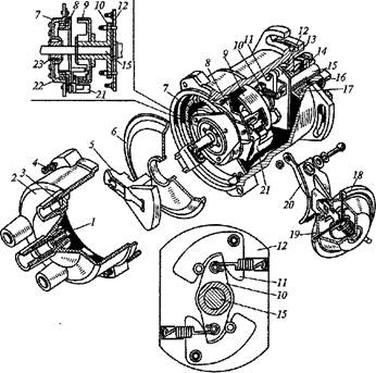
Rice. 12. Sensor - ignition distributor:
1, 3 - electrodes; 2 - lid; 4 - screw; 5 - rotor; 6 - screen; 7 - holder; 8, 10, 12 - plates; 9 - contactor; 11 - weight; 13 - frame; 14- cuff; 15 - shaft; 16 - clutch; 17 - sleeve; 18 - regulator; 19 - diaphragm; 20 - thrust; 21 - sensor; 22 – bearing; 23 - support
Weights are mounted on the drive plate on the axles 11. Follower plate connected to the contactor 9, can turn with him on the shaft 15 within small limits. When the centrifugal governor is operating, the driven plate rotates the contactor relative to the sensor and automatically changes the ignition timing depending on the engine speed. A vacuum regulator is fixed on the housing of the sensor-distributor 18 ignition timing. His diaphragm 19 through traction 20 articulated with the movable plate 8, on which the sensor is installed 21. During the operation of the vacuum regulator, the sensor, together with the movable plate, rotates relative to the contactor. This automatically changes the ignition timing depending on the load on the engine or vacuum under the throttle valves of the carburetor. The sensor - the distributor of ignition is established horizontally in a back part of the engine. Its shaft is driven by a camshaft through a clutch 16, the protrusion of which enters the groove of the camshaft shank.
Contact-transistor ignition system switch designed to turn off the low voltage circuit when the breaker contacts are opened. The transistor switch (Fig. 13) has a housing 1, cast from aluminum alloy, which is equipped with fins for better cooling.
Transistor 4 placed in a special well 5, and the remaining elements - inside the switch case. electrolytic capacitor 6 and pulse transformer 3 located separately. The remaining elements are combined into a common block 2, filled with compound mass and equipped with a heat sink 8. The bottom of the switch is closed with a metal bottom 7, which is attached to the body with rivets.
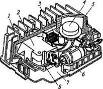
Rice. 13. Switch:
1 - frame; 2 - block; 3 - transformer; 4- transistor; 5 - well; b - capacitor; 7 - bottom; 8 - heat sink
Contactless ignition switch converts the control pulses of a non-contact microelectronic sensor into current pulses in the primary winding of the ignition coil. The systems use an electronic switch. With the passage of a positive pulse from the proximity sensor, when the voltage reaches its maximum value, the output transistor of the switch opens, and current flows through the primary winding of the ignition coil. At the moment when the voltage at the output of the sensor drops to a minimum, the output transistor of the switch closes, breaking the circuit of the primary winding of the ignition coil, and a high voltage pulse is induced in its secondary winding.
Spark plug provides an electric spark in the engine cylinder. In the contact ignition system of engines, non-separable candles are used.
In the steel case 5 (Fig. 14), a core is rolled, which is a ceramic (silumin) insulator 2, inside which there is a contact rod 1 and the central electrode I
The contact rod is filled in the insulator with conductive glass sealant 4, excluding the breakthrough of gases through the insulator. A contact sleeve is screwed onto the thread of the upper end of the rod for attaching the tip of the high voltage wire. The candle body in the upper part has a hexagon 3 turnkey, and in the lower part - external thread 8, with which the spark plug is attached to the cylinder head. A side electrode is attached to the body 10. Sealing ring 7 made of soft iron eliminates the leakage of gases from the engine cylinder through the threads of the spark plug body. copper washer 6, sealing the gap between the case and the insulator, simultaneously removes heat from the insulator to the case, maintaining the temperature of the thermal cone (skirt) of the insulator within certain limits (500 ... 600 ° C), which is necessary for normal operation engine.
Spark plugs are marked, for example A17DV. The letters and numbers in the marking of the candle mean: A - thread M14x 1.25; 17 - glow number; D - thread length, equal to 19 mm; B - the lower part of the insulator protrudes from the housing.
Non-separable spark plugs are used in contact-transistor and non-contact engine ignition systems. They differ in the shape of the insulator, the increased thickness of the side electrode and the presence of an anti-corrosion coating on the body. All this increases the reliability of their operation at higher voltages and increases durability.
Rice. 14. Spark plug:
1 - rod; 2 - insulator; 3 - hexagon; 4 - glass sealant; 5 - frame; 6 - washer; 7 - ring; 8 - thread; 9, 10 – electrodes
The spark plugs and ignition coil are connected to the ignition distributor by high voltage wires. These wires have resistances distributed along their length to reduce radio interference generated by the ignition system during operation. In addition, the high-voltage wires of the engine ignition system in the tips of the spark plugs have interference suppression resistances.
ignition switch provides switching on and off of the ignition system, starter, instrumentation and other devices. On passenger cars, ignition switches with an anti-theft device are used.
The ignition switches used on passenger cars also have a special locking device against restarting the starter without first turning off the ignition. The locking device prevents the starter from being accidentally started while the engine is running, which could damage the starter drive.
2.4 Lighting system
The lighting system ensures the operation of the vehicle in conditions of poor visibility (at night, in fog, etc.). It includes outdoor and indoor lighting. The lighting system includes headlights, front and rear lights, license plate lights, interior lights, instrument cluster and engine compartment lights, fuses and switches.
headlights illuminate the road in front of the vehicle in poor visibility conditions. Cars use a two-headlight lighting system. Headlight (Fig. 15) - round. A holder is installed in the headlight housing 5 6 with springs 8 optical element 1.
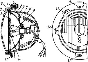
Rice. 3.15. Headlight:
1 - optical element; 2 - diffuser; 3 - bezel; 4, 11, 12 - screws; 5 - body; 6 - holder; 7 - reflector; 8 - spring; 9 - lamp; 10 - screen
The optical element of the headlight, consisting of a reflector 7, diffuser 2, lamps 9 and screen 10, attached to the holder 3 with screws 11. The headlight bulb is a double filament, with a power of 45 W for high beam and 40 W for low beam. Screen 10, installed in front of the lamp, blocks direct light from the lamp filaments and creates a clear upper boundary of the low beam beam. This provides good lighting road in front of the car and reduces the possibility of blinding oncoming drivers Vehicle. screws 4 And 12 allow you to change the position of the holder 6, and with it the optical element 1 in the vertical and horizontal planes when adjusting the headlights. The screws are screwed into plastic nuts that prevent them from self-unscrewing. The nuts are fixed in the headlight housing.
block headlight(fig.16, A) - rectangular, combines a headlight, a side turn signal and a marker lamp. The block headlight has a plastic housing 2, to to which a glass diffuser is glued in front 1.
Behind the body is closed with a removable plastic casing 6 with a seal 7. All this prevents dust and moisture from getting inside the headlight. A reflector with a lamp 5 lights and a lamp are installed in the housing 8 overall light. On the outer side of the block headlight under its diffuser 1 a plastic orange diffuser and a lamp are placed 3 side turn signal. Diffuser 1 is made of colorless glass with high transparency. Its outer surface is smooth, while the inner surface consists of a complex system of prisms that scatter light in a horizontal direction. Headlight reflector - steel, rectangular. Behind it is inserted lamp 5 headlights.
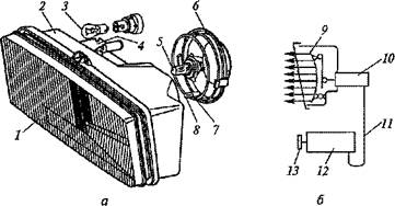
Rice. 3.16. block headlight (A) and hydraulic corrector circuit (b):
1 - diffuser; 2 - frame; 3, 5, 8 - lamps; 4 - nest; 6 - casing; 7 - sealant; 9 - reflector; 10, 12 - cylinders; 11 - a tube; 13 - handle
The lamp is halogen, filled with iodine vapor and an inert gas. Its luminous efficacy and durability are twice that of a conventional lamp. In addition, the light output of the lamp does not decrease during operation, since the tungsten filaments in it do not deposit on the inner walls and the lamp does not darken. Lamp 5 has two filaments: 60W high beam and 55W low beam. The high beam filament is placed at the focus of the reflector, and the dipped beam filament is in front of it and is partially covered from below by a special metal screen that limits the upward propagation of light. The £ 4W bulb is for vehicle size indication, and the 4W bulb is 3 with a power of 21 W - for signaling the maneuvering of the car. There is a special socket on the body of the block headlight for attaching the tip of the headlight hydrocorrector.
Hydrocorrector(Fig. 16, b) allows you to change the angle of the headlights depending on the load on the car. It consists of a master cylinder 12, working cylinders 10, connecting tubes 11, filled with a special fluid that does not freeze at low temperatures.
The hydraulic corrector is controlled by a handle 13, located on the instrument panel. Under the action of fluid pressure, the headlight beams are set to the desired position as a result of the movement of the reflector 9 lights. The headlights on the car are adjusted by rotating two special screws located at the rear of the headlight housing. The screws rotate the reflector in the vertical and horizontal planes.
Front lights are used to indicate the dimensions of the car, parking lighting and light signaling when maneuvering. The front lamp of the car (Fig. 17) is two-section, rectangular. In a zinc die-cast housing 1 lantern are two single-filament lamps. Lamp 2 with a power of 5 W is designed to indicate the dimensions of the car, and lamp 1 with a power of 21 W is for signaling the maneuvering of the car. Diffuser 5 front lamp - plastic, monolithic, two-color. It is installed in the housing on a rubber gasket. 4. Outer part 6 diffuser orange color and is intended for signaling when maneuvering, and the inner part 7 is colorless, designed to indicate the dimensions of the car.

Rice. 17. Front light:
1 - frame; 2, 3 - lamps; 4 - pad; 5 - diffuser; 6, 7 - diffuser parts
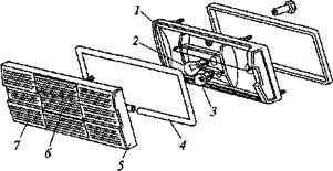
Rice. 18. Rear light:
1 - body; 2, 3 - lamps; 4 - pad; 5 - diffuser; 6 - central section; 7 - outer part
Rear lights are used to indicate the dimensions of the car, light signaling when turning, braking, and for lighting the road and signaling when reversing. Passenger cars usually have rectangular taillights. Rear light (Fig. 18) - four-section. In a zinc die-cast housing 1 there are four single-filament lamps. Three lamps 2 have a power of 21 W, and the lamp 3 - 5 W. The first three are the brake, turn signal and reversing lights, and the last is the position light. The body of the lantern is closed with diffuser 5. The diffuser is plastic, monolithic, multi-section, three-color. It is installed in the housing on a rubber gasket. 4. The outer part 7 of the orange diffuser is intended for signaling when the car is maneuvering. Central section 6 - colorless, serves to signal reversing. The remaining sections of the diffuser are red and are intended for signaling when braking and indicating the dimensions of the car.
2.5 Alarm system
The alarm system ensures the safety of the vehicle. The system includes light and sound signaling.
TO light signaling include front, rear, side turn indicators and their switch, as well as brake (brake), reverse and their switches. The front direction indicators are located in the headlamps or headlights of the vehicle. Rear direction indicators, brake and reverse signals are located in the rear lights of the car. Side direction indicators are located on the front fenders of the car body. The side turn signal consists of a plastic housing, an orange plastic diffuser and a 4 W lamp. The lamp is located inside the indicator body, and the diffuser is welded to the body.
TO sound alarm include sound signals that, if necessary, notify pedestrians and drivers of vehicles about the presence of a car. On cars, electric vibration sound signals of a tonal or noise type are used. They are located in the engine compartment, where they are mounted on brackets.
On passenger cars, two beeps are usually used, one high and the other low. The signals are tuned into a harmonic chord and act simultaneously. The current passing through the signal winding (Fig. 19) magnetizes the core 7, which attracts the armature 9 and causes deflection of the elastic steel membrane 1, fixed between the body 6 and ring 4. In this case, the armature acts on the elastic plate 5 and opens the contacts 2. The current in the winding is interrupted and the core is demagnetized. Membrane 1 returns to its original position, and contacts 2 close. The signal operation is repeated with a contact vibration frequency of 400...500 Hz. Air vibrations caused by the membrane create sound, and the diffuser 3 (resonator) provides melodic sound. The appropriate tone and timbre of the sound depends on the thickness and diameter of the membrane, as well as the diameter of the resonator. In a high tone signal, the membrane is thinner than in a low tone signal. Both audio signals do not have horns and are noise type audio signals.
On passenger cars, one sound signal with a horn is also installed, which acts as a resonator. This is a tone type signal. The specific tone of the signal is provided by the thickness of the membrane and the configuration of the horn. There is an adjustment screw on the body of the sound signal, which allows you to change the strength and frequency of the sound of the signal.
![]()
Rice. 19. Beep:
1 - membrane; 2 - contacts; 3 - diffuser; 4 - ring; 5 - plate; 6 - frame; 7 - core; 8 - winding; 9 - anchor
2.6 Instrumentation
Control and measuring instruments are designed to monitor the state and operation of individual systems and mechanisms of the vehicle. Gauges include gauges for fuel level in the fuel tank, coolant temperature in the cooling system and oil pressure in the engine lubrication system. In addition, there are a number of indicator lamps: fuel reserve, oil pressure, battery charge, carburetor air damper, outdoor lighting, direction indicators, high beam headlights, transfer case differential lock, brake fluid level, parking brake, heated rear window, rear fog light, alarm. Instrumentation also includes a voltmeter, speedometer, electronic tachometer and econometer.
The voltmeter shows the battery voltage with the engine off and the generator voltage with the engine running. The speedometer measures the speed of the car and the distance traveled (daily and total since the start of operation). It is driven by a flexible shaft from a special drive. The tachometer monitors the engine speed. The econometer (vacuum gauge) measures the vacuum in the intake manifold of the engine and allows you to choose the most economical mode of driving the car, in which fuel consumption will be the lowest. It has a mechanical drive. Instrumentation and control lamps on vehicles are located on the instrument panel. On passenger cars, usually all control and measuring instruments, together with control lamps, are combined in the instrument panel.
List of used literature
1. Sarbaev V.I. Car maintenance and repair. - Rostov n / a: "Phoenix", 2004.
2. Vakhlamov V.K. Technique of road transport. - M.: "Academy", 2004.
3. Barashkov I.V. Brigade organization of maintenance and repair of vehicles. - M .: Transport, 1988.


