Calculation light lighting by the method of light flux, point, or by the method of specific power, can be carried out for any room. But if the luminous flux utilization factor method is used to calculate the general uniform illumination, then the point method is more often used to calculate the illumination of local places, and the specific power method is used to determine the approximate power of luminaires.
In addition, the calculation method depends on the known lighting parameters and its final destination. Therefore, in order not to be unfounded, let's analyze each of these methods separately and step by step.
As we have already indicated above, there are three main methods for calculating lighting - this is the luminous flux utilization factor method, the point method and the specific power method. Let's take a look at each of them separately.
Calculation according to the luminous flux utilization factor method
This calculation method can be performed for two cases - when the exact number of lamps is known and their power must be calculated, or when the lamp power is known and their number must be calculated. Let's look at both options.
The calculation is made according to the formula:

Let's look at each of the values from this formula separately, and see what it depends on.

So:
- Emin- this is the minimum normalized value of illumination for a given room. This value is set in Table 1 of SNiP 23-05-95, and depends on such indicators as the characteristics of visual work, the characteristics of the background and the type of lighting. For individual rooms this indicator is given in Table 2 of SNiP 23-05-95.

- S is the area of the room. Everything is quite logical here, because the larger the area of \u200b\u200bthe room, the more light is needed to illuminate it. And we cannot ignore this factor.
- K s is the safety factor. This indicator takes into account that during operation the lamp will be contaminated, and its luminous flux will decrease. In addition, this indicator allows you to take into account the reduction of the reflected component from the walls of the ceiling and other surfaces. Indeed, in the process of operation, the paints of these surfaces fade, and are also amenable to contamination. The instruction advises to take the safety factor for incandescent lamps equal to 1.3, and for gas-discharge lamps equal to 1.5. More precisely, it can be selected according to Table 3 of SNiP 23-05-95.

- Z - coefficient of uneven illumination. This value depends on the uniformity of the distribution of luminaires over the entire area of the room, as well as on the presence of shading objects. This value is calculated by the formula:

E cf is the average value of the illumination in the room, and E min is, respectively, its minimum value.
Note! For most rooms, illumination unevenness is strictly limited. So, for rooms in which works I-II visual discharges, the Z coefficient should not exceed 1.5 for fluorescent lamps, or 2 for other lights. For other premises, this coefficient is 1.8 and 3, respectively.
- N is the number of lamps installed in the room. It depends on the selected lighting system.
- n - the number of lamps in the lamp. If single-lamp fixtures are used, then its value is equal to one. For more, put the corresponding number.
- ɳ - luminous flux utilization factor. It is defined as the ratio of the radiated and incident on the work surface, the luminous flux of all lamps. But to determine it, you should use special reference literature. After all, this parameter is a derivative of the room index, the reflection coefficient of the walls and ceiling, as well as the type of lamp.

Using the luminous flux utilization factor method, it is possible to calculate the number of required fixtures, with a known value of the luminous flux. To do this, you should use the formula -

The values in this formula do not differ from the option considered above, so we will not consider this formula in more detail.
The calculation by the point method contains some differences for spotlights, and for the so-called light bands. Under the light strips mean fluorescent lamps. Let's look at both options.

So:
- Let's start with the calculation of spotlights. At the very first stage of the calculation, we should calculate the height H p. This height is the difference between the height of the luminaire suspension and the normalized height of the minimum illumination.

- The height of the lamp suspension is the distance from the ceiling to the lamp itself. It depends on the structure of the lamp.

- With a normalized height of minimum illumination, everything is a little more complicated. As we said above, in Table. 2 SNiP 23-05-95 you can find the minimum allowable lighting for almost any room.
- At the same time, the height for which this norm is indicated may differ. Usually it varies from 0 to 1.0 meters. This is due to the fact that in some rooms it is necessary to provide maximum illumination in the floor area, and for others at the level of movement or table, that is, 0.7 meters.
- In order to obtain the height H p, it is necessary to subtract the two heights discussed above from the height of the room.

- Now we should draw a plan of the room and the placement of lamps, on which we must determine the equidistant point from all the lamps in the room. It is for her that the calculation will be made. In addition, a scaled plan will greatly facilitate the calculation of the point method of lighting in any room. After all, this will allow you to calculate the distance from any of the fixtures to the calculated point - usually it is denoted d.
- We needed to calculate the values of H p and d to obtain the value of horizontal illumination at the desired point. This value is calculated according to special graphs of spatial isolux. And this schedule depends on the type of fixtures.
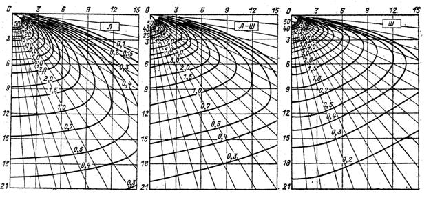
- Having found the parameter H p on the ordinate axis, and the parameter d on the abscissa axis, at their intersection we will get the conditional illumination at the desired point from the given lamp.
- But we need to find the conditional illumination at a given point from each lamp located nearby, and then sum their value. Thus we get the value of E e.
- Now, for calculation by point method, an example formula would be as follows −
- In this formula, 1000 is the conditional luminous flux of the lamp. E n - normalized illumination, k z - safety factor, the choice of which we considered in the previous section of our article.
- µ is the coefficient of additional illumination from neighboring fixtures and reflected light. Usually the value of this indicator is taken from 1 to 1.5.
But for fluorescent lamps, this calculation is not suitable. For it, the so-called point method for calculating luminous bands has been developed. essence this method identical to the option discussed above, and it is quite possible to do it yourself.

To begin with, as in the first variant, we calculate the value of H p. Then we draw a plan of the room and the location of the lamps.
Note! The plan should be drawn to scale. This is necessary to determine point A, for which we are calculating. This point will be located in the middle of the luminous strip, that is, the lamp, and will be removed from this middle by a distance p.

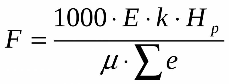
- At the next stage, we determine the linear density of the light flux. This is done according to the formula F \u003d F St × n / L. For this formula, F sv is the luminous flux of the lamp. Its value is equal to the sum of the luminous fluxes of all the lamps in the lamp. N is the number of fixtures in the strip. Usually there is only one such lamp, but there may be other options. L is the length of the lamp.
- At the next stage, we need to find the so-called reduced dimensions - p * and L *. P* = p/H p , and L*=L/2 ×H p . Based on these given dimensions, according to the graphs of linear isolux, we find the relative illumination at a given point. Further calculations are carried out according to the same formula as for spotlights.
Calculation by the method of specific power
The last possible option for calculating lighting is the specific power method. This method is relatively simple, but does not give accurate results. In addition, it requires the use of a large amount of reference literature provided in the video.
The essence of this method is as follows. First of all, we determine the value of H p. We were looking for it in all the options described above, so we will not dwell on it in more detail.

- Further calculation is made according to the tables. In them, we determine the specific power of all lamps necessary for a given room - R beats.
- After that, you can determine the power of one lamp. This is done according to the formula -

Where S is the area of the room, and n is the number of lamps.
Based on the obtained value, we find the nearest higher value of the existing lamps. If the power of the lamps does not meet the requirements of the lamp, then we increase the number of lamps, and repeat the calculation using the specific power method.
Choice of calculation method
Having an idea of how the calculation is made, let's consider which of the methods to choose specifically for your case. After all various methods calculations are designed for different rooms and conditions.
So:
- Let's start with the luminous flux utilization factor method. This method has found enough wide application. It is mainly used to calculate the general lighting in rooms that do not have horizontal elevation differences. Besides, this method will not be able to identify shaded areas, and calculate for them.

- For these purposes, there is a point method. It is used to calculate local lighting, shaded areas and rooms with height differences, as well as inclined surfaces. But it is quite difficult to calculate the total uniform illumination using this method - after all, it does not take into account the reflected and some other components.
- But the method of specific power is one of the simplest. But at the same time, it does not give exact values, and is mainly used as an approximation. With its help, the approximate number of lamps and their power are determined.
In addition, this calculation allows you to determine what is the approximate cost of installation and operation of this lighting system.
Conclusion
Of course, such complex methodologies are completely unnecessary if you are simply creating seedling lighting at home. For this and similar cases, it is enough to apply the normalized indicator of minimum illumination, multiplying it by the area of \u200b\u200bthe room.
And already, based on the value obtained, select the number and power of the lamps. But if we talk about industrial scale, then here one cannot do without careful calculation. And it’s better not to engage in amateur performances in this matter, but to trust a professional design bureau.
The organization of lighting requires taking into account many, very diverse, parameters. Without this, it is impossible to make correct calculations. Methodologies of computational algorithms can be different. And one of their options for lighting is the luminous flux utilization factor method (LUC).
General Lighting Calculation
This article will help you understand what this method is, as well as how it is calculated. You will also learn a lot of useful things for yourself that will help when choosing light sources.
Features of the method
KISP is good for use in situations where it is necessary to make a calculation for uniform and horizontal illumination of a general plan when using various types of lighting fixtures. This method can be used to calculate the level of light supply of a lamp required to provide average illumination in a given situation when there is uniform illumination.
Note! This calculation takes into account the light that was reflected by the surface of the ceiling and walls with a uniform general type of lighting.
The essence of the method for calculating the utilization factor for the luminous flux is that for each specific room it is necessary to calculate its own KISP. It is calculated according to the following criteria:
- the main parameters of the room;
- finishing material, which was used for the final processing of walls and ceilings. Based on the type of surface of the ceiling and walls, their reflective properties will be determined.
Any structure has a limited illuminated volume. It is limited to surfaces (walls, ceiling, etc.) that are able to reflect part of the light radiation that falls on them from the lighting fixture.
When making this calculation, you should know that the reflective surfaces will be:
- ceiling;
- four walls;
- electrical equipment in the room.
Thus, when the space is limited by surfaces with high reflectance values, their reflected component will also be quite large. Therefore, this component must be taken into account in order for the calculation to ultimately turn out to be correct.
Note! An incorrect assessment of the reflectance of various types of surfaces will lead to large errors when using the KISP method.
The features, as well as the main disadvantages, of this method include the following points:
- this calculation is quite laborious and a person who is not very “friends” with mathematics may not be able to cope with it;
- the method can only calculate the parameters of the luminous flux inside the room, i.e. for the interior lighting system.
Now let's take a closer look at the calculation algorithm using the luminous flux coefficient.
The algorithm for using the method
Any mathematical calculation requires compliance with a certain algorithm. If it is not adhered to, then the risk of large errors will increase significantly.
Guided by the method of calculating the coefficient when applying light radiation, you need to do the following:
- determine the lighting system. This means that you need to decide on the type of light source (LED, halogen, fluorescent or other bulbs), the type of lighting fixture that will illuminate a particular area or an entire room;

Variety of light sources
- do the calculation itself.
As you can see, the algorithm is small, but this does not make the CISP any easier. The purpose of the calculation by the method of utilization of the luminous flux is to determine general type lighting. First you need to find out the following parameters:
- how many lighting fixtures are required in order to create a minimum level for illumination (EH);
- lamp power required for a normalized level of luminous flux.
Determining the general backlight type
Having decided to use the option of calculating the luminous flux utilization factor for one light source, you will need to use the following formula:

General Lighting Formula
To determine the required number of lighting fixtures, you can use the following formula:

The formula for calculating the number of lamps
- EH is the minimum level for illumination;
- S is the area to be illuminated;
- k is the safety factor. It will be 1.15 for incandescent bulbs, and 1.3 for DRI, HPS, DRL and fluorescent lamps;
- Z - indicator for minimum illumination. For incandescent bulbs, DRL, HPS and DRI, it will be 1.15, and for luminescent sources light - 1.1;
- N is the number of lamps;
- n is the number of light bulbs in the lighting product;
- h is the coefficient used to use the luminous flux.
Having carried out the calculation using the above formulas, you will get the value of the total light supply and the number of required fixtures for its implementation.
How to choose a lighting system for rooms
The choice of lighting system should be based on several parameters:
- type of work performed;
- standard level of illumination, which is set for each specific room.
In order for the lighting system to accurately meet all possible task options, a choice should be made in favor of its combined version.

Combined lighting
But there are situations when only general lighting is enough. For example, they can be dispensed with in workshops, electroplating, foundries, etc. But combined lighting will be needed on assembly, tool, mechanical sites, etc.
Note! When choosing a lighting system, it is necessary to immediately choose the norms of illumination.
All indicators that need to be taken into account when creating an artificial type of lighting are prescribed in the relevant regulatory documentation - SNiP and SanPin. Moreover, there are norms for all variants of the internal space.

An example of lighting standards according to SNiP
The minimum level of light supply depends on the following parameters:
- category of ongoing visual work;
- contrast and background of the object;
- specifics of the work, etc.
An important point in choosing the type of lighting is to determine the type of light bulb to use as the main light source. Here, the most important thing when choosing will be efficiency in terms of electricity consumption. In addition, it is important to consider other aspects:
- layout;
- building features of the room;
- the state of the air in the room;
- design.
From light sources you can use:

metal halide lamp
- incandescent lamps. They are not economical;
- fluorescent light bulbs. They have high light output, color rendering, as well as low temperature;
- metal halide lamps (DRL and others). Great light output, great power.
Light sources should be selected together with lamps. Lamps are selected according to the following indicators:
- savings requirements;
- lighting parameters;
- conditions of the available air environment.
The lamps themselves, according to light distribution, are of two types of action:
- direct;
- scattered.
In addition, based on the light intensity curves, lighting fixtures are divided into seven groups:
- concentrated;
- cosine;
- wide;
- semi-wide;
- deep;
- sinus;
- uniform.
In accordance with the GOST parameters, lamps are classified according to the class of protection against explosion, water and dust. Which lamp to choose is determined by the requirements of the room in which it will function.
What you need to know about the method
For our calculation method, we need to know the following types of parameters:
- stock indicator (k). It takes into account dustiness, due to which there is a decrease in the luminous flux emitted by the bulbs (see table);

Stock indicator parameters (k)
- indicator of the level of minimum light supply (Z). It is characterized by uneven illumination. It is a function of most variables. Z depends on the distance between the lamps to the calculated height (L / h);
- indicator of the application of the luminous flux (h). To find it, it is necessary to use the room index (i), as well as the expected reflection values for the surfaces in the room (for the floor rp, the ceiling rp and the walls rc).
In this situation, to determine h, you need to know approximate indicators for different surfaces. For bright rooms:
- rp = 70%;
- rc = 50%;
- rr = 30%.
For rooms with low dust emissions:
- rp = 50%;
- rc = 30%;
- rr = 10%.
For rooms with high level dustiness:
- rp = 30%;
- rc = 10%;
- rr = 10%.

The formula for determining the room index
where B, A, h are the width, length and calculated height. To determine the estimated height, use the following formula:
![]()
Estimated Height Calculation
- H is the geometric height of a particular space;
- hsv - the mass of the lamp;
- hp is the height of the available work surface.
Having correctly calculated the required values, you can use the KISP method for any type of premises and fixtures.
Conclusion
The KISP method, despite its complexity, with the correct execution of the algorithm and all calculations, will give you the correct desired values, which will help you calculate the level of general lighting for various types of rooms, when using different types of light sources and models of lighting fixtures.
Artificial lighting happens: general, local and combined.
The task of the calculation is to determine the required power of electric lighting installations to create in industrial premises given illumination, or with a known number of lamps and their power, determine the expected illumination on the working surface.
When designing lighting installations, it is necessary to solve a number of issues:
1. Select the type of light source (where the air temperature is less than +10°C and less than 90% of the rated voltage - incandescent lamps, in other cases - fluorescent lamps.
2. Choose a lighting system - general, local, combined. The combined lighting system is more economical, the general lighting system is more hygienic.
3. Select the type of fixtures - taking into account air pollution, explosion and fire safety.
4. Make a distribution of fixtures and determine their number.
5. Determine the rationing of lighting in the workplace - on the nature of the work performed, the lighting system, light sources.
The calculation of artificial lighting is carried out by three main methods:
1. By the coefficient of use of the luminous flux;
2. Point method;
3. Watt method (power density)
The graphical method of Professor A. A. Trukhanov is also used.
To calculate the total uniform illumination with a horizontal working surface
the main method is the luminous flux utilization factor. Light flow
lamps F L with incandescent lamps or the luminous flux of a group of luminaire lamps with fluorescent lamps is calculated by the formula:
where is the normalized minimum illumination, lx;
The area of the illuminated room, m 2;
Minimum illumination coefficient, 1.1-1.5;
Safety factor, 1.4 - 1.8;
The number of lamps in the room;
The coefficient of use of the luminous flux of lamps,%.
The value of the coefficient is determined according to the tables, depending on the reflectance of the light flux and the indicator of the room, determined by the formula:
where , - the size of the room, m;
Height of luminaires above the design surface, m
Having calculated the luminous flux F according to the table, they select nearest lamp and determine the power of the entire lighting system.
The point method is used to calculate localized local illumination, illumination of inclined planes and to check the calculation of uniform general illumination, when the reflected light flux can be neglected (Fig. 3.12.).

Fig.3.12. Scheme for calculating illumination by an accurate method.
The point method is based on an equation relating illumination and light intensity:
where is the light intensity in the direction from the source to a given point on the surface;
Distance from the luminaire to the calculated point;
The angle between the normal of the working surface and the direction of the light flux to the source;
Enter the safety factor and replace with , and then
Data on the distribution of light intensity are given in reference books.
Glasses are cleaned - with a slight emission of dust - 2 times a year, a significant emission of dust - 4 times a year, lamps - from 4 to 12 times a year, depending on the dustiness of the room.
It is expedient to use this method when calculating the general uniform illumination of horizontal surfaces, taking into account the light fluxes reflected from the walls, ceiling and floor. Reflection coefficient values for various materials and coatings.
The luminous flux in each formula is found by the formula:
F \u003d (E N ∙ S ∙ K Z ∙ Z) / (N ∙ ) ,
where E H is the specified minimum illumination, lx;
K Z - safety factor;
S - illuminated area, m 2;
Z - coefficient of non-uniformity equal to - 1.2;
N is the total number of fixtures, pcs.;
Reference luminous flux coefficient in relative units.
The room index is calculated by the formula:
i = (A ∙ B) / ,
where A, B - the length and width of the room, m;
H p - estimated height, m.
Based on the luminous flux found, using the reference data, the type, size of the lamp and its power are selected.
F \u003d (E N ∙ S ∙ K Z ∙ Z) / (N ∙ ) \u003d (100 ∙ 864 ∙ 1.3 ∙ 1.2) / (14 ∙ 34) \u003d 283.15
i = (A ∙ B) / = (72 ∙ 12) / = 1.83
Lamp type - LEC65. Power P = 65 W. Voltage U = 220V, diameter 40 mm, Luminous flux Ф = 3450.
6. Specific power method.
This method is a simplified method of the luminous flux utilization factor and is recommended for the calculation of lighting installations in secondary rooms and for the preliminary determination of the lighting load at the initial design stage.
Calculation formula of the method:
P rl \u003d (P beats ∙ S) / N,
where P rl is the estimated power of the lamp, W;
N - the number of lamps in the room, pcs.;
P beats - specific power of general uniform lighting, W / m 2;
S is the area of the room, m 2.
The specific power values depend on the type and light distribution of the luminaire, the size of the room, the reflection coefficients of the walls, ceiling and floor, the height of the luminaire suspension and are selected according to reference literature.
Calf - 3.7 W / m 2.
According to the calculated lamp power P rl and catalog data, the lamp size and its power are selected so that the condition is met:
0.9 ∙ P rl P l 1.2 ∙ P rl
P rl \u003d (P beats ∙ S) / N \u003d (3.7 ∙ 864) / 14 \u003d 228.3 W,
0.9 ∙ P rl P l 1.2 ∙ P rl
0.9 ∙ 228.3 P l 1.2 ∙ 228.3
205,47 240 273,96
General information.
According to the requirement of the PUE (12), the demand coefficient for the group lighting network of buildings and all emergency lighting links should be taken equal to one.
Group lines of internal lighting must be protected by safety or automatic switches for a working current of not more than 25A.
Group lines supplying gas-discharge lamps with a unit power of 125 W are equipped with fuses or automatic switches for current up to 63A.
Each group line should contain no more than 20 incandescent, DRL, DRN, sodium lamps per phase. This number also includes sockets.
In group lines supplying lamps with a power of 10 kW or more, no more than one lamp should be connected to each phase.
Fluorescent lamps should be used with ballasts (ballasts) that provide individual reactive power compensation up to a power factor cos of at least 0.9. For DRL, DRI and sodium lamps, both group and individual reactive power compensation is applicable.
In lighting networks with gas discharge lamps, devices for suppressing radio interference must be provided in accordance with the current regulations of the Ministry of Communications.
Lighting > Calculation of lighting using the utilization factor and power density method
UTILIZATION FACTOR METHOD
See also the section on websor :
Choice of calculation method
Utilization method
Simplified forms of the utilization rate method
When calculating using the utilization factor method, the required flux of lamps in each lamp Ф is found by the formula
where E is the specified minimum illumination, lx; k - safety factor; S - illuminated area, m2; z - ratio Esr:Emin; N is the number of fixtures (as a rule, planned before the calculation); h - utilization factor in fractions of a unit.
In such premises as offices, drawing rooms and some others, where the position of the worker is strictly fixed and creates partial shading, a shading coefficient of about 0.8 should be entered into the denominator of formula (5-1), but this is not yet generally accepted.
The nearest standard lamp is selected according to Ф, the flux of which should not differ from Ф by more than -10 ... + 20%. If it is impossible to choose with such an approximation, N is corrected. With a uniquely set Ф (fluorescent lamps designed for certain lamps, low-power lamps, the use of which is advisable with lamps of the highest possible power), the formula is solved with respect to N. For all other values \u200b\u200bgiven, the formula can be used to determine expected E.
When calculating fluorescent lighting, the number of rows and is most often initially planned, which is substituted in (5-1) instead of N. Then, under Ф, one should mean the flux of lamps of one row.
With the selected type of luminaire and the spectral type of lamps, the lamp flux in each F1 luminaire can have only 2-3 different meanings. The number of fixtures in a row N is defined as
The total length N of fixtures is compared with the length of the room, and the following cases are possible:
a. The total length of the fixtures exceeds the length of the room: it is necessary either to use more powerful lamps (which have more flux per unit length), or increase the number of rows, or arrange rows of double, triple, etc. fixtures.
b. The total length of the lamps is equal to the length of the room: the problem is solved by the device of a continuous row of lamps.
in. The total length of the luminaires is less than the length of the room: a row is accepted with breaks evenly distributed along it l between lamps.
From several possible options, the best one is selected on the basis of technical and economic considerations.
It is recommended that l did not exceed approximately 0.5 of the design height (except for multi-lamp lamps in the premises of public and administrative buildings).
Included in (5-1) coefficient z , which characterizes the unevenness of illumination, is a function of many variables and to the greatest extent depends on the ratio of the distance between the lamps to the calculated height (L:h), with an increase in which beyond the recommended values z increases sharply. When L:h, not exceeding the recommended values, you can take z equal to 1.15 for incandescent lamps and DRL and 1.1 for fluorescent lamps when the lamps are located in the form of luminous lines. For reflected illumination, one can assume z =1.0; when calculating the average illumination z not taken into account.
To determine the utilization factor h is the room index i and the reflection coefficients of the surfaces of the room are presumably estimated: the ceiling -, walls - , calculated surface or floor -(See Table 5-1).
Table 5-1 Approximate wall and ceiling reflectance values
The nature of the reflective surface |
Reflection coefficient, % |
Whitewashed ceiling; whitewashed walls with windows covered with white curtains |
|
Whitewashed walls with uncovered windows; whitewashed ceiling in damp rooms; clean concrete and light wooden ceiling |
|
Concrete ceiling in dirty rooms; wooden ceiling; concrete walls with windows; walls covered with light wallpaper |
|
Walls and ceilings in rooms with a lot of dark dust; continuous glazing without curtains; red brick not plastered; walls with dark wallpaper |
|
The index is found by the formula
![]()
where A is the length of the room; B is its width; h - estimated height.
For rooms of practically unlimited length, i=B/h can be considered.
To simplify the definition of i serves as a table. 5-2. In one of the top three rows, depending on the visually estimated ratio A:B, there is the value of h closest to the given one; moving the view along the column finds two area values between which the given value is enclosed, and moving to the right until the "indices" column finds the value i .
For example, if A=20m, B=10m and h \u003d 4.3 m, then for the interval A: B \u003d 1.5...
2.5, moving to the right between the values S=157 m2 and S=219 m2, we find i =1,5.
In all cases, i is rounded to the nearest tabular value; at i > 5, i = 5 is taken into account.
Valuesutilization factors for luminaires with incandescent lamps (for example) is given in Table. 5-3.
Table 5-2 Table for determining room index

Table 5-3 Light utilization factors. Lighting fixtures with incandescent lamps

Since the number of standard sizes of luminaires for fluorescent lamps has increased many times in recent years, it seemed impossible to give a separate table for each luminaire. Luminaires with similar lighting characteristics are combined into groups, for each of which the average values of utilization factors are given.
The given utilization factor tables do not cover the entire range of luminaires. If you need to more accurately determine the utilization factors, you should use the method for calculating them, described in section.
In most cases, especially for luminaires for public buildings, an approximate calculation is sufficient. h using the table. 5-19 and 5-20, performed according to the scheme: according to the shape of the luminous intensity curve in the lower hemisphere, its type is determined: according to the catalog data of the lamp, the fluxes of the lower (Ф 1) top (Ф 2 ) hemispheres; the first is multiplied by the value of the utilization factor according to Table. 5-19, the second - according to the table. 5-20; the sum of the products gives the total usable flux, which is divided by the lamp flux (usually 1000 lm) to find the utilization factor.
Example 1 Determine the utilization factor for i = 1.5, hanging lamp. According to the factory catalog F1=0.64 and F2=0.80-0.64=0.16.
The light intensity curve in the lower hemisphere is closest in shape to curve D.
Using tables, we find
Example 2 In the room for which the index is defined above, 12 PPR lamps are installed and it is required to provide E = 30 lux at k = 1.5. Given.
With the indicated data and i=1.5 according to the table. (as tab. 5-3) we find h = 0.32, whence
![]()
We choose a lamp 200 W, 2800 lm.
Example 3 In the same room, three longitudinal rows of LDOR lamps with LB lamps are installed and it is required to provide E = 300 lux at k = 1.5. In table. (as tab. 5-3) we find h =0.44. Stream of lamps of one row
![]()
If we accept lamps with 2x40 W lamps (with a total flux of 5700 lm), then it is necessary to install 75,000:5700 = 13 lamps in a row; luminaires with lamps 2 X 80 W (with flux 9920) - 8 luminaires. Since the length of the row is about 20 m, in both cases the fixtures fit in the row.
The first option has some advantages, in which the gaps between the lamps are smaller.


