An overhead power line (VL) is a device for transmitting and distributing electricity through wires located in the open air c attached with insulators and fittings to supports or brackets of engineering structures (bridges, overpasses, etc.). The device of the overhead line, its design and construction must comply with the "Electrical Installation Rules" (PUE), which are mandatory for all power lines, except for special ones (for example, contact networks tram, trolleybus, railway and etc.)
Insulators and fittings
The semiconductor coating may consist of a strip of colloidal carbon impregnated paper wrapped directly around the conductor. This arrangement is used, for example, in cables insulated with impregnated paper. In cables with insulation removed from current construction, the semiconductor coating is applied by extrusion using a suitable semiconductor material.
Its main characteristics are as follows: high dielectric strength, low dielectric loss, high partial discharge resistance, good thermal performance. Its great disadvantage is that it is very hygroscopic and that the absorption of moisture greatly degrades its dielectric properties, for this reason the paper insulation must be completely dried during the cable manufacturing process and protected by an airtight liner.
Classification and operating modes of overhead lines. Air lines power lines are usually designed to transmit alternating three-phase current and by appointment are divided into:
- ultra-long distance voltage of 500 kV and above, serving mainly for communication between individual power systems;
- trunk lines with a voltage of 220 and 330 kV, which are used to transmit energy from powerful power plants, as well as to communicate between power systems and combine power plants within power systems (usually connect power plants with distribution points);
- distribution voltages of 35, PO and 150 kV, serving for the power supply of enterprises and settlements of large areas (connect distribution points with consumers and represent branched networks with transformer substations);
- power lines of 20 kV and below, used to supply electricity to consumers.
Consumers of electricity according to the reliability of power supply are divided into three categories:
- the first includes consumers whose power supply disruption can lead to a danger to people's lives, damage to equipment, mass product defects, disruption of important elements of the urban economy;
- to the second - consumers whose power supply interruption leads to massive undersupply of products, downtime of equipment and workers, disruption of the normal activities of a significant part of the urban population;
- to the third - other consumers.
This mineral impregnating oil is mixed with vegetable resin to increase its viscosity and thus prevent the insulating oil from migrating by gravity to the lower parts of the plant. In cables for higher voltages, the insulation is maintained under pressure in various ways.
Supports for wires
It becomes plastic by increasing the temperature which allows it to be hot extruded onto the conductors and then hardened by running the cable through a bath of cold water. The most commonly used thermoplastics as insulation electrical wires are polyvinyl chloride and polyethylene. It has the disadvantage of having a high dielectric constant and therefore high electrical losses, which limits its use at higher voltages. Polyethylene obtained by polymerization of ethylene gas has excellent characteristics as electrical insulation: dielectric strength comparable to impregnated paper and lower dielectric loss. They also have a higher thermal conductivity than impregnated paper, making heat dissipation easier. The disadvantages of polyethylene are that degradation of the insulation can occur due to partial discharges created by ionization, its melting point is quite low at 110 ° C, which limits the operating temperature of polyethylene insulated cables at 75 ° C. Improvements in thermal performance have been developed by high density polyethylene and vulcanized or cross-linked polyethylene. They are usually applied by extrusion and subjected to a vulcanization process by raising the temperature to the required values. The most used are natural rubber and synthetic rubber, known collectively as elastomers, and more recently some derivatives of polyethylene. Thermoplastics: synthetic organic materials obtained by polymerization. . The shield also serves to shield the cable from the potential caused by external electric fields and to protect personnel by effectively grounding them.
By voltage, overhead power lines are divided into two groups by the Rules for Electrical Installations: overhead lines with voltages up to 1000 V (low voltage) and overhead lines with voltages above 1000 V (high voltage). For each group of lines, the technical requirements for their device are established. The rated linear voltage of three-phase current lines is regulated by GOST 721-62 and can have the following values: 750, 500, 330, 220, 150, 110, 35, 20, 10, 6 and 3 kV, as well as 660, 380 and 220 V.
This can be done with a tape made of metallized paper or a tape of non-magnetic metal with a thickness of about 8 mm, rolled over the insulation. In high voltage cables, in which the electrical gradients applied to the insulation are low, distribution control electric field is not required, and therefore a metal screen can be dispensed with; however, it is sometimes used in low voltage cables to avoid potential induction in conductors due to external electric fields.
Documents regulating overhead lines
It can be metal, thermoplastic, elastomeric or textile, depending on the application of the cable. In cables used in distribution networks, everything is also covered with steel tape for mechanical protection, in which case the cable is called "armed".
According to the electrical mode of operation, the lines are divided into. lines with isolated neutral, when common point winding (neutral) is not connected to the grounding device or is connected to it through devices with high resistance, and with a solidly grounded neutral, when the neutral of the generator or transformer is tightly connected to the ground.
Gauge means cross-sectional area or any other parameter that defines it. Two international systems are adopted to determine the caliber of drivers. Mills is a unit of English length, which is defined as a thousandth of an inch.
Depending on this unit, the length can determine the cross-sectional area indicated by the conductors, so it takes a round thousand, which corresponds to the area of a circle whose diameter is a thousand. It should then be well understood that a thousand circles is a unit of area that relates the driver's caliber to his area. It is used to indicate solid wires and braided conductors, if the area of the conductor is required, its diameter is known in inches, it must be controlled only.
In networks with isolated neutral line insulation must be at least line voltage, since when one phase is shorted to earth, the voltage of the other two phases relative to earth becomes equal to linear. In networks with a solidly grounded neutral, if one phase is damaged, short circuit through the ground and line protection disconnects the damaged section. In this case, phase overvoltage does not occur and the line insulation is selected according to the phase voltage. The disadvantage of these networks is the large value of the earth fault current and the disconnection of the line in case of a single-phase earth fault. In our country, networks with a solidly grounded neutral are used in systems with voltages up to 1000 V and from 110 kV and above.
You can make an equivalent between English and US units. This article is part thesis for an electrical engineering degree. Developed by Bachillers: Bustillos Ramirez, Alida Caroline Perez Lisbon, Jesus Christ University of Carabobo.
Justification for high voltage
Power lines are familiar because they are part of our Everyday life. But have you ever wondered why they don't have the same height or what is the purpose of this green colored plate equipment mounted on top of the pylons? Here are 3 keys to recognize various types lines in the blink of an eye.
Depending on the mechanical state, the following operating modes of overhead lines are distinguished:
- normal - wires and cables are not broken;
- emergency - wires and cables are cut off completely or partially;
- assembly - in the conditions of installation of supports, wires and cables.
Mechanical loads on the elements of overhead lines to a large extent depend on the climatic conditions of the area and the nature of the terrain along which the line passes. When designing overhead lines, they take as a basis highest value values of wind speed and wall thickness of ice formed on wires, observed in the area once every 15 years for 500 kV overhead lines and once every 10 years for 6-330 kV overhead lines.
The transmission network contains lines high voltage and very high voltage. Increasing the voltage limits the power loss due to the Joule effect. Thus, high and very high voltages make it possible to transport electricity to long distances. These pylons range in height from 10 to 90 m and are located at a distance of several hundred meters from each other. The higher they are, the higher the voltage.
Low and medium voltage electrical distribution networks are usually placed on wooden or concrete poles. From a height of 10 to 14 m, they are at a distance of one hundred meters from each other. On each pylon, electrical cables are attached to chains of insulators. This plate equipment is often green in color. Their role is to support the cable conductor and provide electrical insulation metal frame. These chains are usually made of glass or porcelain cakes "stacked" on top of each other.
The area through which the overhead line passes, depending on the accessibility for people, transport and agricultural machines, is divided according to the PUE into three categories:
- populated areas include the territory of cities, towns, villages, industrial and agricultural enterprises, ports, marinas, railway stations, parks, boulevards, beaches, taking into account the boundaries of their development for the next 10 years;
According to the mode of operation depending on the mechanical condition
The number of these plates varies depending on the line voltage. Distributor lines have three or less. What does "license plate" say? To check if the pylon you found matches our network, there is the right way: check the label on each of them. This allows you to accurately identify each piece of equipment. It always includes the pylon number, line name and voltage level.
Substations are a complex electrical complex, which is part of the transmission and distribution of electrical energy, designed to receive, convert and distribute electrical energy. There are two main types: distribution and transformer. Their complex structure suggests the existence of many basic and additional elements.
- to uninhabited - undeveloped territory, partially visited by people and accessible to transport and agricultural machines (gardens, orchards and areas with separate, rarely standing buildings and temporary structures are also considered uninhabited);
- to hard-to-reach - the territory inaccessible to transport and agricultural machines.
The device and the main elements of the overhead line. Overhead power lines consist of supporting structures (pillars and bases), wires, insulators and linear fittings. In addition, the structure of the overhead line includes devices necessary to ensure uninterrupted power supply to consumers and normal operation lines: lightning protection cables, arresters, grounding, as well as auxiliary equipment for the needs of operation (high-frequency communication devices, capacitive power take-off, etc.)
The main ones are power transformer or automatic transformer, electric wires, cable and overhead lines, low and high voltage switchgear, busbar systems, etc. another important element is the power supply system for the auxiliary needs of the substation, which includes transformers, panels alternating current and direct current, rechargeable batteries.
The main devices also include protection and control systems, automation and grounding system, lightning protection system, electricity reading devices and reactive power compensation system. Lighting, ventilation, air conditioning and fire protection systems can be used for auxiliary devices.
Overhead transmission line supports support the wires at a given distance between themselves and from the earth's surface. The horizontal distances between the centers of the two supports on which the wires are suspended is called the span, or span length. There are transitional, intermediate and anchor spans. The anchor span usually consists of several intermediate spans.
System subsystems The system subsystems are powered by high voltage and ultra high voltage transmission lines and are used for transit transmission by importing and exporting electricity over long distances, voltage transformation and large power transformation. They are built for two or three voltages.
System substations are built on large facilities and have a permanent highly qualified staff on duty. The system for remote and telemetry information is also very advanced. They consist of two or three high voltage and ultra high switchgears. high levels voltages in them require the use of a powerful high-voltage switchgear to switch them electrical circuits. To reduce system performance, switchgears are used for switching in an isolated medium with very good thermal properties - oil, elastic.
The angle of rotation of the line is the angle between the directions of the line in adjacent spans.
The vertical distance hg (Figure 1, a) between the lowest point of the wire in the span to the crossed engineering structures or to the surface of the earth or water is called the gauge of the wire.
Figure 1 - Size (a) and sag (b) of the wires:
F, f - sag of wires; hg-gauge of the wire from the ground, A, B - wire suspension points
This scheme allows you to simultaneously disconnect all connections without interrupting the power supply to other lines. This gives the system maximum security. regional substations. They are fed from power plants or system substations via overhead or cable lines and provide electricity in areas with a large number of users. Their primary voltage is 220 kV or 110 kV and the secondary voltage is 6 kV, 10 kV or 20 kV. Their primary high voltage allows them to be built both outdoors and in residential and heavily polluted areas - for example, indoor switchgear.
The sag f of the wire is the vertical distance between the lowest point of the wire in the span and the horizontal straight line connecting the suspension points of the wire on the supports. If the height of the attachment points is different, the sag is considered relative to the highest and lowest points of the wire attachment (F and f in Figure 1, b).
Tension is the force with which a wire or cable is pulled and fixed on supports. The tension varies depending on the strength of the wind, the ambient temperature, the thickness of the ice on the wires and can be normal or weakened.
For medium voltage installations are built as closed switchgear, and Electric Energy exported from air or cable lines. Their scheme is such that they are powered by three 110 kV outputs. Typically, the voltage is converted by two bidirectional power transformers, and the 110 kV switchgear is built with two prefabricated bushings. The number of collector busbars in a 20 kV switchgear is determined by the number, nature and characteristics of the supplied consumers.
Functionally, substations are further subdivided into. Transit - they are used not only to power users, but also to power their mixed and neighboring power systems; Converters - Substations designed to convert current with a different frequency or current rectification; Traction - for the needs of electric transport.
The margin of safety, or the safety factor of the elements of an overhead power line, is the ratio of the minimum design load that destroys this element to the actual load in the most severe conditions.
The mechanical stress of the material is the load on the elements of the overhead line, referred to the unit area of their working section. For example, the tension of a wire, related to its cross section, determines the mechanical stress of the wire material.
The temporary resistance is called the maximum allowable mechanical stress of the material, after exceeding which the destruction of the product begins.
Overhead lines are called lines intended for the transmission and distribution of EE through wires located in the open air and supported by supports and insulators. Overhead power lines are constructed and operated in a wide variety of climatic conditions and geographical areas, are subject to atmospheric influences (wind, ice, rain, temperature changes). In this regard, overhead lines should be built taking into account atmospheric phenomena, air pollution, laying conditions (sparsely populated areas, urban areas, enterprises), etc. From the analysis of overhead lines conditions, it follows that the materials and designs of lines must meet a number of requirements: economically acceptable cost, good electrical conductivity and sufficient mechanical strength of the materials of wires and cables, their resistance to corrosion, chemical attack; lines must be electrically and environmentally safe, occupy a minimum area.
Structural design of overhead lines. The main structural elements of overhead lines are supports, wires, lightning protection cables, insulators and linear fittings.
According to the design of the supports, single- and double-circuit overhead lines are most common. Up to four circuits can be built on the line route. Line route - a strip of land on which a line is being built. One circuit of a high-voltage overhead line combines three wires (sets of wires) of a three-phase line, in a low-voltage line - from three to five wires. In general, the structural part of the overhead line (Fig. 3.1) is characterized by the type of supports, span lengths, overall dimensions, phase design, and the number of insulators.
The span lengths of overhead lines l are chosen for economic reasons, since with an increase in the span length, the sag of the wires increases, it is necessary to increase the height of the supports H so as not to violate the permissible size of the line h (Fig. 3.1, b), while the number of supports and insulators will decrease by lines. Line gauge - the smallest distance from the lowest point of the wire to the ground (water, roadbed) should be such as to ensure the safety of people and vehicles under the line. This distance depends on the nominal voltage of the line and the local conditions (inhabited, uninhabited). The distance between adjacent phases of a line depends mainly on its rated voltage. The design of the overhead line phase is mainly determined by the number of wires in the phase. If the phase is made by several wires, it is called split. The phases of the overhead lines of high and ultra-high voltage are split. In this case, two wires are used in one phase at 330 (220) kV, three - at 500 kV, four or five - at 750 kV, eight, eleven - at 1150 kV.
Overhead lines. VL supports - structures designed to support wires at the required height above the ground, water, or some engineering structure. In addition, grounded steel cables are suspended from the supports, if necessary, to protect the wires from direct lightning strikes and related overvoltages.
The types and designs of supports are varied. Depending on the purpose and placement on the overhead line, they are divided into intermediate and anchor. The supports differ in material, design and method of fastening, tying wires. Depending on the material, they are wooden, reinforced concrete and metal.
intermediate supports the most simple, serve to support wires in straight sections of the line. They are the most common; their share on average is 80-90% of the total number of overhead line supports. The wires are attached to them with the help of supporting (suspended) garlands of insulators or pin insulators. Intermediate supports in normal mode are loaded mainly from the own weight of wires, cables and insulators, hanging garlands of insulators hang vertically.
Anchor supports installed in places of rigid fastening of wires; they are divided into terminal, angular, intermediate and special. Anchor supports designed for the longitudinal and transverse components of the tension of the wires (tension garlands of insulators are located horizontally) are tested highest loads, so they are much more complicated and more expensive than intermediate ones; their number on each line should be minimal.
In particular, end and corner supports installed at the end or at the turn of the line experience constant tension of wires and cables: one-sided or by the resultant of the angle of rotation; intermediate anchors, installed on long straight sections, are also calculated for one-sided tension, which can occur when part of the wires breaks in the span adjacent to the support.
Special supports are of the following types: transitional - for large spans crossing rivers, gorges; branch lines - to carry out branches from the main line; transpositional - to change the order of the wires on the support.
Along with the purpose (type), the design of the support is determined by the number of overhead lines and the mutual arrangement of wires (phases). Supports (and lines) are made in a single or double circuit version, while the wires on the supports can be placed in a triangle, horizontally, reverse "Christmas tree" and a hexagon or "barrel" ( rice. 3.2).
![]()
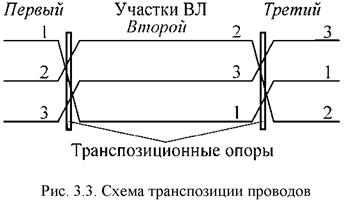
The asymmetric arrangement of the phase wires with respect to each other (Fig. 3.2) causes the unequal inductances and capacitances of different phases. To ensure the symmetry of a three-phase system and phase alignment of reactive parameters on long lines (more than 100 km) with a voltage of 110 kV and above, the wires in the circuit are rearranged (transposed) using appropriate supports.
With a full cycle of transposition, each wire (phase) evenly along the length of the line occupies in series the position of all three phases on the support (Fig. 3.3).
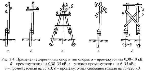
wooden supports (rice. 3.4) are made from pine or larch and are used on lines with voltages up to 110 kV in forest areas, now less and less. The main elements of the supports are stepchildren (prefixes) 1, racks 2, traverses 3, braces 4, under-traverse bars 6 and crossbars 5. The supports are easy to manufacture, cheap, and easy to transport. Their main drawback is their fragility due to the decay of wood, despite its treatment with an antiseptic. The use of reinforced concrete stepchildren (attachments) increases the service life of the supports up to 20-25 years.
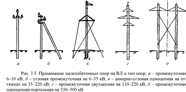
Reinforced concrete supports(Fig. 3.5) are most widely used on lines with voltage up to 750 kV. They can be free-standing (intermediate) and with braces (anchor). Reinforced concrete supports are more durable than wooden ones, easy to operate, cheaper than metal ones.
Metal (steel) supports ( rice. 3.6) are used on lines with a voltage of 35 kV and above. The main elements include racks 1, traverses 2, cable racks 3, braces 4 and foundation 5. They are strong and reliable, but quite metal-intensive, occupy a large area, require special reinforced concrete foundations for installation and must be painted during operation to protect against corrosion.


