The energy consumed by railway transport is spent on providing train traction and powering non-traction consumers: stations, depots, workshops, train traffic control devices.
The power supply system of electrified railways includes power plants, district transformer substations, networks and power lines, which are called external power supply. Internal or traction power supply includes traction substations and electric traction network.
Power plants generate three-phase alternating current with a voltage of 6 ... 21 kV and a frequency of 50 Hz. At transformer substations, the voltage is increased to 750 kV, depending on the transmission distance electrical energy consumers. Near the places of electricity consumption, the voltage is reduced to 110 ... 220 kV and fed into the district networks, to which traction substations of electrified railways and transformer substations of roads with diesel traction are connected.
The traction network consists of contact and rail wires, which represent the supply and suction lines, respectively. Plots contact network connected to neighboring traction substations.
Railways use direct current systems with a rated voltage of 3000 V and single-phase alternating current rated voltage 25 kV, frequency 50 Hz.
The main parameters characterizing the power supply system of electrified railways are the power of traction substations, the distance between them and the area of the contact suspension.
DC traction substations perform two functions: they lower the voltage of the input three-phase current and convert it to constant. The voltage level at the current collector of the electric rolling stock at DC in any block section there should be no more than 4 kV and no less than 2.7 kV, and in some sections at least 2.4 V is allowed. Taking into account these requirements, DC traction substations are placed close to each other (10 ... 20 km) with the maximum allowable cross section of the contact wire.
AC traction substations serve only to lower the AC voltage (up to 27.5 kV) received from power systems. On directions electrified on alternating current with a rated voltage of 25 kV, the distance between traction substations is 40 ... 60 km. The cross-sectional area of the wires of the contact network in a single-phase alternating current system is approximately two times less than with direct current. However, the design of locomotives and electric trains with alternating current is more complicated, and their cost is higher.
Docking of contact networks of electrified lines on different current systems is carried out at special railway stations.
A contact network is a set of wires, structures and equipment that ensures the transmission of electrical energy from traction substations to current collectors of electric rolling stock.
The contact network consists of consoles, insulators, a carrier cable, a contact wire, clamps and strings and is mounted on metal or reinforced concrete supports(Fig. 22.1).
Simple (on secondary station and depot tracks) and chain overhead contact networks are used. A simple contact suspension is a freely hanging wire, which is fixed on supports. In a chain suspension (Fig. 22.1), the contact wire is not freely suspended between the supports, but is attached to the carrier cable using wire strings. Due to this, the distance between the surface of the head and the contact wire remains almost constant. The distance between the supports with a chain suspension is 70 ... 75 m.
The height of the contact wire above the surface of the rail head on stages and stations should be at least 5750 mm, and on crossings - 6000 ... 6800 mm.
The contact wire is made of hard-drawn electrolytic copper of a special profile (Fig. 22.2). It can have a sectional area of 85, 100 or 150 mm2.
Contact network supports are used reinforced concrete (up to 15.6 m high) and metal (15 m or more). The distance from the axis of the outermost track to the inner edge of the supports on hauls and stations must be at least 3100 mm. On existing electrified lines and in difficult conditions, it is allowed to reduce the specified distance to 2450 mm - at stations and to 2750 mm - on hauls.
To protect the contact network from damage, it is sectioned (divided into separate sections - sections) using air gaps (insulating mates), neutral inserts, sectional and mortise insulators.
Air gaps suit for electrical insulation adjacent areas from each other. The air gap is performed in such a way that during the passage of the current collector of the electric rolling stock, the mating sections are electrically connected. At the boundaries of the air gaps, contact network supports are installed that have a distinctive color.
A neutral insert is a section of the contact network in which there is constantly no current. The neutral insert consists of several air gaps connected in series and, when passing through the electric rolling stock, provides electrical isolation of the mating sections.
Hauls, intermediate stations, groups of tracks in station parks are divided into separate sections. Connection or disconnection of sections is carried out by means of sectional disconnectors placed on the supports of the contact network or using sectioning posts. Sectioning posts are equipped with protective equipment - circuit breakers from short circuits.
To ensure the safety of maintenance personnel and other persons, all metal structures (bridges, overpasses, traffic lights, hydro columns, etc.) that directly interact with elements of the contact network or are located within a radius of 5 m from them are grounded or equipped with disconnect devices. Also, in the zone of influence of the contact network, all underground metal structures are isolated from the ground to protect them from damage by stray currents.
Contact network device: 1 - support; 2 - thrust; 3 - console; 4, 9 - insulators; 5 - carrying cable: 6 - contact wire; 7 - string; 8 - latch
Electric rail transport is the most productive, economical and environmentally friendly. Therefore, from the middle of the 20th century to the present, active work has been carried out to transfer railways to electric traction. Currently, more than 50% of Russian railways are electrified. In addition, even non-electrified sections of railways are in need of electrical energy: it is used to ensure the functioning of signaling systems, centralization, communications, lighting, computer technology, etc.
Electricity in Russia is generated by enterprises in the energy industry. Railway transport consumes about 7% of the electricity produced in our country. It is spent on providing train traction and powering non-traction consumers, which include railway stations with their infrastructure, locomotive, wagon and track facilities, as well as train traffic control devices. Small enterprises and settlements located near it can be connected to the railway power supply system.
According to Clause 1 of Appendix No. 4 to the PTE in railway transport, a reliable power supply of electric rolling stock, signaling devices, communications and computer technology should be provided as consumers of electric energy of category I, as well as other consumers in accordance with the category established for them.
comprises external network (power plants, transformer substations, power lines) and internal networks (traction network, power supply lines for signaling and communication devices, lighting network and etc.).
A three-phase variable is generated electricity voltage 6...21 kV, frequency 50 Hz. To transfer electrical energy to consumers, the voltage is not increased to 250 ... 750 kV and transmitted to long distances with ( power lines). Near the places of electricity consumption, the voltage is reduced to 110 kV with the help of and fed into the regional networks, to which, along with other consumers, electrified railways are connected and supply non-traction consumers, the current of which is supplied by a voltage of 6 ... 10 kV.
Purpose and types of traction networks
designed to provide electrical energy to electric rolling stock. It consists of contact and rail wires, which are respectively nourishing and suction line. The sections of the traction network are divided into sections (partition) and connected to neighboring ones. This makes it possible to load the substations and the contact network more evenly, which generally helps to reduce electricity losses in the traction network.
On Russian railways, two traction current systems are used: permanent and single-phase variable.
Rules technical operation regulated nominal voltage levels on current collectors of electric rolling stock: 3 kV- at direct current and 25 kV- with a variable. At the same time, voltage fluctuations acceptable from the point of view of ensuring the stability of movement are determined: at direct current from 2,7 before 4 kV, with a variable from 21 before 29 kV (Clause 2 of Appendix No. 4 to the PTE).
On railways electrified on DC, perform two functions: they lower the voltage of the supplied three-phase current using and convert it to DC using. From the traction substation electricity through the protective quick release switch is fed into the contact network by - feeder, and from the rails it returns back to the traction substation along.
Main shortcomings of the DC power supply system are its constant polarity, relatively low voltage in the contact wire and current leakage due to the inability to provide complete electrical insulation of the upper track structure from the lower one (""). The rails, which serve as current conductors of one polarity, and the subgrade are a system in which an electrochemical reaction is possible, leading to metal corrosion. As a result, the service life of rails and metal structures located near the railway track is reduced. To reduce this effect, special protective devices - cathode stations and anode earthing switches.
Due to the relatively low voltage in the DC system to obtain the required power of traction rolling stock ( W=UI) a large current must flow through the traction network. For this, traction substations are placed close to each other (every 10 ... 20 km) and the cross-sectional area is increased, sometimes using double and even triple contact wire.
With alternating current, the required power is transmitted through the contact network at a higher voltage ( 25 kV) and, accordingly, lower current strength compared to a direct current system. Traction substations in this case are located at a distance of 40...70 km from each other. Their technical equipment is simpler and cheaper than DC traction substations (there are no rectifiers). In addition, in a single-phase alternating current system, the cross-sectional area of the wires of the contact network is approximately two times smaller, which can significantly save expensive copper. However, the design of locomotives and AC electric trains is more complicated and their cost is higher.
The docking of contact networks of lines electrified at direct and alternating current is carried out at special railway stations -. Such stations have electrical equipment - that allow both direct and alternating current to be supplied to the same sections of the station tracks. The operation of such devices is interconnected with the operation of centralization and signaling devices. The installation of docking stations requires large investments. When the creation of such stations seems impractical, two-system and operating on both types of current are used. When using such an EPS, the transition from one type of current to another can occur while the train is moving along the haul.
Contact network device
Contact network- this is a set of wires, supporting structures and other equipment that ensures the transmission of electrical energy from traction substations to electric rolling stock. The main requirement for the design of the contact network is to ensure reliable permanent contact of the wire with the current collector, regardless of the speed of trains, climatic and atmospheric conditions. There are no duplicated elements in the contact network, so its damage can lead to a serious violation of the established train schedule.
In accordance with the purpose of electrified tracks, they use simple and chain air contact suspensions. On secondary station and depot tracks, at a relatively low speed, it can be used (" tram" type), which is a freely hanging stretched wire, which is fixed with insulators on supports located at a distance of 50 ... 55 m from each other.
At high speeds, the sagging of the contact wire should be minimal. This is ensured by the design in which the contact wire between the supports is attached to carrying cable using frequently spaced wire strings. Due to this, the distance between the surface of the rail head and the contact wire remains almost constant. For a chain suspension, unlike a simple one, fewer supports are required: they are located at a distance of 65 ... 70 m from each other. On high-speed sections, they are used, in which a auxiliary wire, to which a contact wire is also attached with strings. In the horizontal plane, the contact wire is located relative to the track axis with a deviation of ±300 mm at each support. This ensures its wind resistance and uniform wear of the contact plates of current collectors. To reduce the sagging of the contact wire during seasonal temperature changes, it is pulled to the supports, which are called, and suspended from them through the system. The greatest length of the section between anchor supports (anchor section) is set taking into account the permissible tension of the worn contact wire and reaches 800 m on straight sections of the track.
In accordance with Clause 4 of Appendix No. 4 to the PTE contact wire suspension height above the level of the rail head on the hauls and stations should be not less than 5750 mm, and on crossings - not less than 6000 mm. The maximum allowable height of the contact wire suspension - 6800 mm. The contact wire is made from hard-drawn electrolytic copper section 85 , 100 or 150 mm 2. For the convenience of attaching wires with clamps, use MF.
For reliable operation of the contact network and ease of maintenance, it is divided into separate sections - sections by using air gaps and neutral inserts, as well as.
When the current collector of the electric rolling stock passes along it, with its skid, it briefly electrically connects both sections of the contact network. If, according to the power conditions of the sections, this is unacceptable, then they are separated, which consists of several consecutive air gaps. The use of neutral inserts is mandatory on lines electrified on alternating current, because. neighboring sections of the contact network can be powered by different phases coming from the power plant, electrical connection which are unacceptable with each other. The EPS must follow in the run-down mode and with the auxiliary machines turned off. To protect the places of sectioning of the contact network, special signal signs "" are used, installed on the supports of the contact network.
Connection or disconnection of sections is carried out by means of a contact network placed on the supports. Disconnectors can be controlled remotely using a pole-mounted electric drive connected to the energy manager console, or manually using manual drive, .
The scheme for equipping station tracks with contact wires depends on their purpose and type of station. Above the turnouts, the contact network has the so-called, formed by the intersection of two contact suspensions.
On mainline railways, they use contact network supports. The distance from the axis of the extreme path to the inner edge of the supports on straight sections must be at least 3100 mm. In special cases, on electrified lines, it is allowed to reduce the specified distance to 2450 mm- at stations and before 2750 mm- on the run. On hauls, they are mainly used individual cantilever suspension of contact wire. At stations (and in some cases, on hauls), it is applied group suspension of contact wires on and crossbars.
To protect the contact network from short circuit between adjacent traction substations are equipped with safety switches. All metal structures directly interacting with elements of the contact network or located within a radius of 5 m from them, ground(connected to the rails). On lines electrified at direct current, special diode and spark are used. To protect the elements and equipment of the contact network from overvoltage (for example, due to a lightning strike), some supports are installed with arc horns.
For electrical isolation of elements of the contact network under voltage (contact wire, carrier cable, strings, clamps) from grounded elements (supports, consoles, crossbars, etc.) are used. According to the functions performed, insulators are suspended, tension, fixative, console, by design - dish-shaped and rod, and according to the material from which they are made -, and.
On electrified railways, the rails run reverse traction current. To reduce power losses and ensure the normal operation of automation and telemechanics devices on such lines, the following features of the structure of the track structure are provided:
- welded to the rail heads on the outside of the track (shunts), which reduce electrical resistance rail joints;
- the rails are isolated from the sleepers with the help of rubber gaskets in the case of reinforced concrete sleepers and impregnation of wooden sleepers with creosote;
- crushed stone ballast is used, which has good dielectric properties, and a gap of at least 3 cm is provided between the rail sole and the ballast;
- on lines equipped with automatic blocking and electrical interlocking, insulating joints are used, and in order to pass traction current around them, they install or frequency filters.
AC/DC docking stations
One of the ways to join lines electrified on different types of current is the sectioning of the contact network with the switching of individual sections to be powered by DC or AC feeders. The contact network of docking stations has groups of isolated sections: direct current, alternating current and switchable. The switched sections are supplied with electricity through. The contact network from one type of current to another is switched with special motor drives installed at the grouping points. Two supply lines are connected to each point: AC and DC from the DC-AC traction substation. Feeders of the corresponding type of current of this substation are also connected to the contact network of the necks of the docking station and adjacent hauls.
To exclude the possibility of supplying current to individual sections of the contact network that does not correspond to the rolling stock located there, as well as the exit of the EPS to sections of the contact network with a different current system, the switches are blocked with each other and with devices electrical centralization. Switch control is included in a single route-relay centralization system for controlling switches and station signals. The station attendant, collecting any route, simultaneously with the installation of arrows and signals in the required position, makes the appropriate switching in the contact network.
Route centralization at docking stations has a system for counting the arrival and departure of electric rolling stock on the track sections of the switched sections of the contact network, which prevents it from being energized by another kind of current. To protect the equipment of power supply devices and electric rolling stock of direct current in case of contact with them as a result of any disturbances in the alternating current voltage, there is special equipment.
Requirements for power supply devices
Power supply devices must provide reliable power supply:
- electric rolling stock for the movement of trains with established weight norms, speeds and intervals between them with the required movement sizes;
- signaling devices, communications and computer technology as consumers of electrical energy of category I;
- all other consumers of railway transport in accordance with the established category.
A backup power supply source for automatic and semi-automatic blocking must be in constant readiness and ensure uninterrupted operation of signaling devices and crossing signaling for at least 8 hours, provided that the power has not been turned off in the previous 36 hours. must exceed 1.3 s.
To ensure reliable power supply, periodic monitoring of the state of structures and power supply devices, measurement of their parameters, diagnostic devices, and scheduled repairs should be carried out.
Power supply devices must be protected from short circuit currents, overvoltages and overloads in excess of established standards.
Metal underground structures (pipelines, cables, etc.), as well as metal and reinforced concrete structures located in the area of lines electrified at direct current, must be protected from electrical corrosion.
Within artificial structures, the distance from the current-carrying elements of the current collector and parts of the contact network under voltage to the grounded parts of structures and rolling stock must be at least 200 mm on lines electrified at direct current, and not less than 270 mm- on alternating current.
For the safety of maintenance personnel and other persons, as well as to improve protection against short-circuit currents, they are grounded or equipped with devices protective shutdown metal supports and elements to which the contact network is suspended, as well as all metal structures located closer than 5 m from the live parts of the contact network.
Karelin Denis Igorevich ® Orekhovo-Zuevsky Railway College named after V.I. Bondarenko "2017
The infrastructure of electric rolling stock necessarily includes contact networks. Thanks to this provision, the supply of target pantographs is realized, which, in turn, set in motion vehicles. There are many varieties of such networks, but they are all a combination of cables, fixing and reinforcing elements that provide power from. Also, the contact network is also used to service fixed objects, including various crossings and lighting stations.
General information about contact networks
This is part of a technical structure, which is part of a complex of electrified tracks and roads. The main task of this infrastructure is to transfer energy from to electric rolling stock. In order to ensure the possibility of supplying equipment with energy from several substations, the contact network is divided into several sections. Thus, sections are formed, each of which is fed by a separate feeder from a specific source.
Sectioning is also used to facilitate repair operations. For example, in the event of a line failure, power transmission will be interrupted in only one section. Faulty wiring can be connected to an operating substation if necessary, reducing downtime. In addition, the contact network of railways is provided with special insulators. This decision is due to the fact that the accidental formation of an arc at the time of passage of the current collectors can disrupt the main sheath of the wires.
The device of contact networks
Networks of this type are a whole complex of electrical infrastructure components. In particular, a typical device of this facility includes power cables, special hangers, reinforcement and its special parts, as well as supporting structures. To date, an instruction is used, in accordance with which parts, fittings of the contact network and wires undergo a special procedure of thermal diffusion galvanization. Elements are made of low-carbon and are subjected to protective treatment to increase the strength and durability of communications.
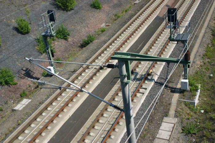
Features of overhead contact networks
Overhead networks are the most common due to space savings and more efficient organization electrical lines. True, there are also disadvantages of such a device, which are expressed in higher costs for installation and maintenance. So, the overhead contact network includes a carrier cable, fittings, wires, arrows with intersections, as well as insulators.
The main design features of networks of this type are reduced to the method of placement. Communications are suspended on special supports. In this case, sagging wires may be noted between the installation points. It is impossible to completely eliminate this flaw, but its presence can be harmful. For example, if the support of the contact network allows for strong sagging, then the current collector moving along the cable at the suspension points may lose contact with its line.
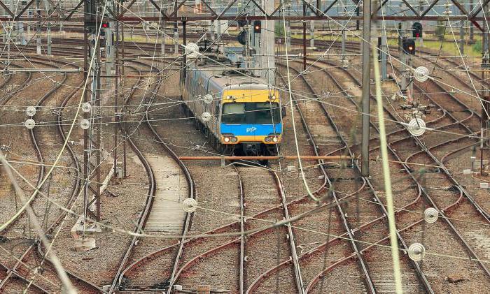
Railway contact networks
In this case, we are talking about the classic version of the contact network. It is the railways that use the largest volumes of materials for the electrification of rolling stock. The wire itself for such purposes is made of electrolytic hard-drawn copper with a cross-sectional area of up to 150 mm 2. As for the supporting elements, the railway contact network is provided by reinforced concrete or metal installations, the height of which can reach 15 m. The gaps from the axis of the extreme tracks to the outer sides of the supports at stations and stages are no more than 310 cm. True, there are exceptions - for example, in In difficult conditions, the technology allows the gap to be reduced to 245 cm. Traditional methods of protecting wires of this type are used - division into separate sections, the use of insulators and neutral inserts.
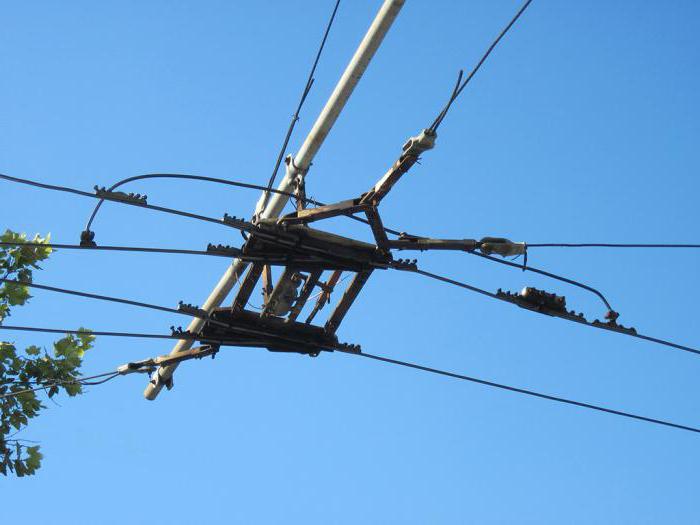
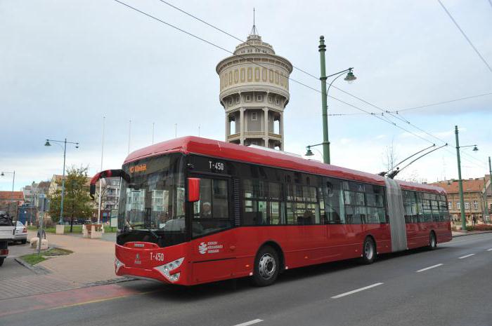
Trolleybus contact network
Compared to rail transport, the movement of a trolleybus does not imply a permanent electrical connection with the surface. The requirements for maneuverability are also increasing, which leads to changes in the organization of the electrification infrastructure. These differences determined the main feature of the electrical networks for trolleybuses - the presence of two-wire lines. At the same time, each wire is fixed at small intervals and is provided with reliable insulation. As a result, the contact network becomes more complicated both in straight sections and in the areas of branching and intersections. The features include wide application sectioning with appropriate insulators. But in this case, the sheath not only protects the wires from contacts with each other, but also protects the material at the intersection. In addition, the use of arc pantographs and pantographs is not allowed in the infrastructure of trolleybus networks.
Contact networks of trams
In tram contact networks, wires made of copper and alloys of similar characteristics are usually used. Also, the possibility of using steel-aluminum wires is not excluded. The coupling of sections with different suspension heights is carried out with a wiring slope in relation to the longitudinal profile of the track. In this case, the deviation can vary from 20 to 40%, depending on the complexity and conditions of the line laying section. On straight sections, the contact network of the tram is located in a zigzag pattern. At the same time, the zigzag step - regardless of the type of suspension - does not exceed four spans. It is also necessary to note the deviation of the contact cables from the axis of the pantograph - this value, as a rule, is no more than 25 cm.
Conclusion
Despite the technological development of electrification systems, contact networks in the main design options retain the traditional device. Changes in terms of improving technical and operational parameters affect only some aspects of the use of parts. In particular, the contact network of railways is increasingly supplied with elements that have undergone thermal diffusion galvanization. Additional processing element base, undoubtedly, increases the reliability and durability of lines, but contributes to a radical technical improvement to a minimal extent. The same applies to trams and trolleybuses. electrical networks, in which, however, recently the fixing devices, the strength of the reinforcement and parts of suspended structures have been significantly improved.
Page 22 of 35
24. Basic schemes and designs of the contact network
Dimensions of contact network devices. The normal height of the contact wire above the level of the rail heads on the hauls is taken equal to 6250 mm, at the stations - 6600 mm. The minimum height must be at least 5750 mm at the hauls and 6250 mm at the stations, the maximum - no more than 6800 mm.
The distance from the front face of the supports to the axis of the track is taken on the straight sections of the track of the haul and stations is 3100 mm, in the recesses when the supports are located behind the ditch - 4900 and 5700 mm, in cramped conditions on the hauls the dimensions are reduced to 2750 mm and at the stations - up to 2450 mm.
The distance from the reinforcing wires suspended on the contact network supports on the field side to the ground in the middle of the span must be at least 6000 mm, and the distance from them to the excavation slope must be at least 4500 mm.
In artificial structures, the distance from the elements of the pantograph and parts of the contact network under voltage to the grounded parts of structures and rolling stock should be 200 mm in the sections of direct current and 350 mm of alternating current.
Conjugations of anchor sections. The contact network consists of separate anchor sections 1200-1600 m long. To ensure the transition of the pantograph skid from the contact wire of one anchor section to the contact wire of the next, various interface schemes for these sections are used. The interfaces should ensure a smooth transition of the pantograph and uninterrupted current collection for the accepted speeds of movement on the site. On hauls, simple and elastic mates are used. In places where the catenary suspension is sectioned, insulating mates are performed, and in places fed from different phases on AC roads, where it is unacceptable to close adjacent sections with a pantograph, insulating mates with a neutral insert are used (see paragraph 25).
With a semi-compensated suspension, when the speed does not exceed 70 km / h, simple pairings are performed according to a two-span scheme (Fig. 76, a). Between the anchor supports 1 and 3, a transitional 2 is placed, on the console of which, in one double saddle, the supporting cables of both anchor sections are suspended. The contact wires are suspended on strings to the carrying cables and anchored on supports 1 and 3 by 0.5-0.6 m and above the normal height of the wire in the span.
The electrical connection between the wires of the anchor sections is carried out using longitudinal connectors. At the intersection of the contact wires, a restrictive pipe 1-1.5 m long is installed so that when the skid passes, the rise of any wire in this place causes the rise of another. At the intersection of the contact wires, sparking and their increased wear are observed, therefore, a two-span interface is used on the secondary tracks of the stations.
Rice. 76. Simple two-span (a) and elastic three-span (b) pairing of anchor sections
On the main tracks of stations and spans with semi-compensated and compensated suspensions, elastic three-span interfaces of anchor sections are performed (Fig. 76, b). Between the anchor supports 1 and 4, two transitional supports 2 and 3 are placed. The anchored branches of the contact wires between these supports are placed in parallel at a distance of 100 mm with an elevation at the transitional supports by 200 mm relative to the working contact wire. The pantograph from one wire to another passes more calmly in the middle of the transition span.
Air Arrows. The transition of the pantograph from the contact wire of one station track to another is provided by air arrows, which are formed at the intersection of two converging contact suspensions. At the intersection of the contact wires, a restrictive tube 1-1.5 m long is installed on the lower wire.
At high speeds, the air arrows must be fixed, i.e., the wires must be held in the position required for reliable operation with the help of clamps. Therefore, the intersections of the wires are carried out near a flexible or rigid cross member, or a support is specially installed (Fig. 77).
Fixing devices are located at a distance of 1-2 m from the intersection of the contact wires in the direction of the sharp arrow; the intersection of the contact wires should be between the axes of the converging paths and be separated from them at a distance of 400 mm. In the vertical plane, this intersection is located where the distance between the inner edges of the converging rails of the cross is 730-800 mm.
Non-fixed arrows are used on secondary routes, where the speed of movement is low.
Fasteners. To create zigzags of the contact wire on straight sections of the track and offsets at supports on curves, clamps are used. The clamps should be light and easy to move in the vertical and horizontal planes. 
Rice. 77. Layout of a fixed air pointer on a turnout
Rice. 78. Schemes explaining the operation of compressed (a) and stretched (b) retainers
The latches are curved so that when the contact wire is pressed out, the pantograph skid does not touch them. Depending on the direction of the zigzag, the clamps work in tension or compression. With a positive zigzag (see Fig. 76, b, support 1), a compressive force acts on the latch, and with a negative one (support 4), a tensile force. For a compressed latch (Fig. 78, a), the vertical component N of the force is directed downward, which increases the concentrated mass and rigidity, and for a stretched latch (Fig. 78, b), it is upward, which reduces the concentrated mass and rigidity when the current collector passes under this latch. The current collection conditions in the latter case will be better, and the wear of the contact wire will be less. Compressed retainers, if possible, are replaced with reverse articulated retainers and consoles with reverse locking posts (see Fig. 91, d).
By design, the clamps are divided into rigid, articulated, flexible and reverse. The articulated latch (Fig. 79, a, b) consists of the main 1 and additional 2 rods. The additional rod works in tension. It is attached to the main one using a special rack 3. The main rod is suspended with two strings to the carrier cable at a distance of 1.5-2 m on both sides of the console. In this case, only the load from the weight of the additional rod is transferred to the contact wire. In areas with two contact wires, clamps are used for each contact wire with additional rods. 
Rice. 79. Direct articulated (a), reverse articulated (b) and flexible (c) retainers
Reverse clamps are installed on straight sections of the path with positive zigzags and on supports located inside the curves. When the supports are located on the outer side of the curves of small radii, flexible clamps are used (Fig. 79, c), which consist of a curved clamp 4 and a wire 5 with a diameter of 5-6 mm, attached to the insulator 6 at the support.
Strings and clips. Vertical strings are flexible or link. The strings are attached to the wires of the chain suspension with string clamps of a boltless design (previously bolt clamps were used). Boltless clamps are 3-4 times lighter than bolt clamps, which leads to a reduction in metal costs for their manufacture and simplification of installation work. In a semi-compensated suspension, sliding strings are used when the strings are skewed (Fig. 80).
Contact suspension in artificial structures.
Due to the insufficient size of an artificial structure, it is impossible to use standard structures when installing a contact suspension in it. Therefore, under bridges, overpasses (Fig. 81, a), if their height is sufficient, the suspension is passed under the structure and: isolated fenders are installed to prevent it from being pressed against the structure. If the height of the structure is insufficient, an insulated insert is cut into the carrier cable and a bypass is arranged with fastening on the contact wire or away from the path (Fig. 81, b). Other solutions are also possible.
Rice. 80. Sliding string:
1 - rigid triangle: 2 - ring 
Rice. 81. Schemes of the passage of catenary suspension under the pedestrian bridge and overpass:
I - fencing shield; 2 and 5 - fenders of the carrier cable; 3 - sliding string; 4 - insulated insert; 6 - bypass
The contact network supports are installed so that the structure is in the middle of the span.
On bridges with a ride from below, the design of the catenary suspension depends on their dimensions. If the height of the bridge is insufficient, the supporting cable is suspended on U-shaped brackets or special rotary consoles above the wind ties of the bridge (Fig. 82, a), or inside them on transverse cables or other structures fig. 82b).
The most difficult device is the contact network in tunnels. It is made in the form of a chain suspension with a small structural height (400-500 mm) and small span lengths (15-25 m). The suspension is fixed on an insulated console installed in a niche in the upper part of the tunnel, or on flexible insulated ties.
Rice. 82. Schemes of the passage of the contact suspension on bridges with a ride below:
1 - chipper; 2 - bracket; 3 - latch; U GR - rail head level
The height of the contact wire in artificial structures and under them is usually less than in adjacent adjacent areas. On the approaches to the structure, a gradual decrease in the height of the contact wire is provided.
We advise you to read
, diagnosis, treatment Treatment of urogenital chlamydia") Chlamydia urogenital - description, causes, symptoms (signs), diagnosis, treatment Treatment of urogenital chlamydia
Chlamydia urogenital - description, causes, symptoms (signs), diagnosis, treatment Treatment of urogenital chlamydia The benefits and significance of hydroamino acid threonine for the human body L threonine what
 To wait or not to wait for a guy from the army For what reason can they be commissioned from the army
 Baked apples with cottage cheese Baked apples with cottage cheese

