Scheduled repairs in the apartment, a breakdown or any other reason may be a reason for replacement electric meter in your apartment. First of all, we note that you should not buy the device that first catches your eye. It is also not recommended to purchase counters that were in use. Not only the cost of electricity, but also the safety of your entire home will depend on the quality of this, at first glance, not a complicated and standard device.
Consider what kind of electricity meters are, what properties and characteristics they have.
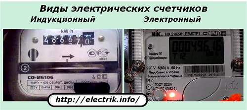
Types of electricity meters
All modern electric meters are divided into induction and electronic.
Induction devices contain two coils: voltage and current coils. The magnetic field that is formed on these coils rotates a movable disk inside the counter, which causes the counting mechanism to move. electrical energy. The higher the network indicators such as voltage and current, the faster the disk rotates, and the faster the indicators on the electric meter dial grow. The main advantages of these types of meters are high reliability and long term services. Induction electricity meters can operate for more than 15 years. Among the disadvantages, one can single out the fact that it is almost impossible to implement an accuracy class higher than 2 on induction meters. Rather, it is possible, but quite difficult and expensive.
In electronic electricity meters, a direct transfer of current and voltage values in digital form to the device memory is implemented. Such meters have a number of advantages, including the possibility of multi-tariff metering of electrical energy, and compact size, and easy transition to a higher accuracy class through the use of special microcircuits, and resistance to unauthorized attempts to steal electricity. The disadvantages of such devices are almost obvious - low reliability (compared to induction meters) and high price.
Characteristics of electricity meters
All electric energy meters, depending on the type, manufacturer and set of functions, have different characteristics, among which are:
- Accuracy class. This indicator is probably the most important technical parameter of electric meters. As the name suggests, the accuracy class characterizes the error of the instrument. Previously, meters with an accuracy class of 2.5 were used (that is, the maximum error could be 2.5%). After the introduction of the new standard (since the mid-90s), they actively began to switch to new electricity meters, the error of which was at least 2.0. Modern electronic meters can provide an accuracy of up to 0.5-1%. The accuracy class is displayed on the instrument panel as a number enclosed in a circle.
- Tariff. The functional advantages of new electronic meters make it possible to implement a multi-tariff approach to the calculation of consumed electrical energy.
- Reliability. Intertest interval. The calibration interval is the period of time between the date of issue of the electric meter and the date of its next calibration. Over time, the parts of the device wear out, the materials age, the accuracy class changes, so it is simply necessary to carry out such a procedure. Calibration intervals for all meters are indicated in the passports for the devices. The service life for a single-phase induction electric energy meter until the next verification is usually 16 years, for an electronic one - 8-16 years. The term for verification of three-phase electricity meters is approximately 6-8 years. The year of verification is indicated on the seals of the instruments.
- Single-phase and three-phase electricity meters. When buying a new meter, you need to clearly know which device you need. You can find out quite simply. To do this, just open specifications power supply of a house or apartment, or look at the scoreboard of an old meter. If the number 220 is indicated, then this means that the meter is single-phase. It is used at a nominal voltage of 220 V. If the inscription 220/380 appears, then the device is three-phase and is designed to operate under a voltage of 380 V.
- Current strength. To date, electricity meters produce those that are designed for a maximum current of 50-60A. With a power input of 15 kW, this will be more than enough. If you have a power input of more than 15 kW, then in such cases it is recommended to purchase devices designed for 100A. You can determine the maximum current by the introductory machine, on the body of which this very desired value will be written. Taking an electric meter with a current margin does not make any sense.
- Mounting method. The counters are mounted either on three screws or on a DIN rail. The first method is designed for standard electrical panels. You can only find electronic devices with a din rail mount. Separately, for this type of fastening, it is necessary to purchase a special box for an electric meter or the din rail itself, which can sometimes come with a meter.
Based on all the characteristics listed above, it is advisable for a potential buyer to decide which device he needs even before going to the store. Sales representatives and stores today can offer a wide range of counters different types and with different settings. We cannot advise an ordinary ordinary consumer to do anything else but to purchase a device from a well-known manufacturer with a long warranty period and service center for repairs in your city. When buying, be sure to pay attention to the integrity of the seals and the year when the electric meter was manufactured and verified. The verification passport must have a manufacturer's stamp. Not all consumers need all the options that are now available on modern electronic electricity meters. Someone, on the contrary, seeks to regularly check the correctness of payment or control when, how much and at what tariff electricity was used.
In any case, the choice always remains with the buyer.
Speciallyfor Dmitry Popenko
 |
Series CE
TsE6807B-1, TsE6807B-2 - electronic counters are single-phase one- and two-tariff, respectively.
Designed to account for active energy alternating current.
| CE 6807 B-1 | CE 6807 B-2 | |
| accuracy class | 2,0 | |
| rated and maximum current, A | 5 - 50 | |
| rated voltage, V | 220 | |
|
power consumption: parallel circuit, VA series circuit, W tariff control circuit, W |
||
| operating temperature range, deg. | -45 … +60 | |
| number of tariffs | 1 | 2 |
| transmission number of main and verification exit | 500/32 000 | |
Series PSC-4TA.03
Designed to account for consumed active AC electricity with a frequency of 50 Hz in three-wire and four-wire networks for housing and communal services, industrial production, power systems.
Two types are produced: PSC-4TA.03.1, PSC-4TA.03.2, have the same metrological characteristics, a single design and are subdivided according to the climatic version.
Stand-alone or as part of an automated power control and management system (ASKUE).
The meters comply with GOST 30206-94 (IEC 687-92). The meters are registered in the State Register of Measuring Instruments under No. 17352-98, certificate of conformity No. ROSS RU.ME34 B 01284 and approved for use in the Russian Federation.
Technical features:
built-in microcontroller;
internal rater;
liquid crystal indicator;
registration and storage of half-hour power cuts for 2 months;
electronic seal;
non-volatile memory;
communication interface RS-485;
two telemetry outputs;
indication of the value of electricity consumed for the last 11 months by tariff zones, as well as consumption exceeding the power limit by tariffs;
meter programming from a computer via RS-485;
lack of self-propelled.
|
rated voltage, V |
3x57.7/100 |
| operating range | 0,85-1,1 |
| limit range | 0,8-1,15 |
| rated current, A | 5 |
| maximum current, A | 7,5 |
| accuracy class | 0,5 |
| network frequency, Hz | 50±2.5 |
| sensitivity threshold, mA | 0,5 |
|
power consumed by the parallel circuit of the meter at rated. voltage active, W full, VA |
no more than 0.8 no more than 1.5 |
| complete. power, consumption each last. meter circuit at rated. value current strength, VA | no more than 1 |
| average daily switching time delay tariff zones in the work. conv. and in the absence e.g. in the network pit., with | no more than ±5 |
| check interval, years | 6 |
| average time of the counter to failure, hour | 35 000 |
| average meter service life before overhaul, years | 30 |
| execution class | IP51 |
|
set and limit operating temperature range, o C PSC-4TA.03.1 PSC-4TA.03.2 |
-20 to +55 -40 to +55 |
| Overall dimensions, mm | 323x170x77 |
| meter weight, kg | no more than 3.0 |
Series CA4-...
Counters SA4I672, SR4I673 and SA4I678 are electrical devices of the induction system, used to account for the electrical energy of alternating current with a nominal frequency of 50 Hz.
For operation indoors in the temperature range from 0 to +40°C and relative. air humidity not more than 80% at a temperature of +25°С.
| accuracy class | connection | nominal current, A | nominal line voltage, V | power consumption, V | |
| SA4 I672M | 2 | through tr-p current | 5 | 380 | 1,5 |
| direct | 10 - 20 | ||||
| SA4 I678 | 2 | direct | 10 - 40 | ||
| 20 - 50 | |||||
| 30 - 75 | |||||
| 50 - 100 | |||||
| SR4U I 673M | 2 | through tr-p current, voltage. | 5 |
Series SET4...
Counter SET4 designed to measure active energy in three-phase four-wire lines AC voltage 380/220V with transformer connection of current circuits. Gives readings directly in kilowatt-hours.
The counter has two pulse output: telemetry output (main) of the transmitter and verification output. The output of the main transmitting device can be used to work in automated systems for collecting and accounting for electrical energy and for checking the meter using the wattmeter-stopwatch method. Verification is used for accelerated verification of the meter.
The counter is issued modifications: in one-tariff - SET4-1/1; in two-tariff - SET4-2/1. Tariff switching is carried out by applying a control signal direct current 12V from the tariff switching device.
Operating conditions
ambient temperature: from -40 to +60°С
relative air humidity (%, at +25°C): 98.
| accuracy class | 2,0 |
| gear ratio of the main transmission device | 250 |
| gear ratio of the main test output | 4 000 |
| current limit values, A | 3x(0.05-7.5) |
| rated current, A | 3x5 |
| rated phase voltage, V | 3х220 |
| maximum current, A | 3x7.5 |
| network frequency, Hz | 50, 60 |
| apparent power consumed by each series. meter circuit, HF A, no more | 0,3 |
| total power consumed by each parallel circuit of the meter, HF A, not more than | 4,0 |
| calibration interval, years, not less | 6 |
| service life, years | 30 |
| Overall dimensions, mm | 75x180x292 |
| weight, kg | 2,0 |
Series SO-I 449M2
SO-I449M2 - single-phase induction meter - an electrical measuring device of an induction system of direct connection, designed to account for the active energy of alternating current in enclosed spaces at temperatures from -20 to + 55 ° C and relative humidity of no more than 80% at a temperature of + 25 ° C in the absence of aggressive vapors and gases.
Counter rotating element - tangential type
The counting mechanism is drum type.
| accuracy class | 2,0 |
| rated voltage, V | 220 or 127 |
| rated current, A | 5 or 10 |
| maximum current, % | 400 Inom. or 600 In |
| frequency Hz | 50 |
| sensitivity threshold, % | 0.45 Inom. |
| power consumption, W | 1,3 |
| verification period, years | 8 |
| Overall dimensions, mm | 203x121x116 |
| weight, kg, no more | 1,5 |
Induction single-phase electricity meter SO-I 449
Accuracy class: 2.0
Maximum current: 60A
Dimensions: 203x121x116 mm
Weight: no more than 1.5 kg
Induction single-phase electricity meter SO-505
Designed to account for energy in single-phase two-wire networks residential buildings and industrial premises.
Accuracy class: 2.0
Rated phase voltage: 220V
Maximum current: 40A
Operating temperature range: -20 to +55°C
Dimensions: 200x128x114 mm
Weight: no more than 1.2 kg
Single-phase microprocessor two-tariff electricity meter TsE6827
Universal system counter for household accounting. Designed to measure and account for electrical energy at two tariffs in two time zones.
Accuracy class: 1.0: 2.0
Rated phase voltage: 220V
Maximum current: 60A
Operating temperature range: -20 to +55°C
Dimensions: 132x214x66.5 mm
Weight: no more than 1.0 kg
Three-phase electricity meter CE680Z
Designed to measure electrical energy at one or two tariffs.
Accuracy class: 2.0
Maximum current: 10A
Operating temperature range: -40 to +55°C
Overall dimensions: 140x150x57 mm
Weight: no more than 0.8 kg
Three-phase electricity meter TsE6805
Designed to measure electrical energy in two directions.
Accuracy class: 0.5
Rated phase voltage: 3x57.7 (3x100)V
Maximum current: 7.5A
Operating temperature range: -20 to +55°C
Weight: no more than 2.0 kg
Three-phase electricity meter TsE6811
Designed to measure and account for electrical energy in one or two directions.
Accuracy class: 1.0
Rated phase voltage: 220(380)V
Maximum current: 100A
Operating temperature range: -25 to +60°C
Dimensions: 177x282x85 mm
Weight: no more than 2.0 kg
Three-phase electricity meter TsE6828
Designed to measure and account for electrical energy at two rates.
Accuracy class: 2.0
Rated phase voltage: 3x220V
Maximum current: 100A
Operating temperature range: -20 to +55°C
Dimensions: 177x282x85 mm
Weight: no more than 3.0 kg
AC active energy meters
| Counter type |
SO-IB1 |
SO-IB2 |
SA4-IB60 |
SA4U-IT12 |
|
| Rated current | |||||
| Maximum current | |||||
| Rated voltage | |||||
| Permissible voltage deviation from Vн | |||||
| Rated frequency | |||||
| Permissible frequency deviations | |||||
| Sensitivity threshold | |||||
| Power consumption in the circuit: voltages | |||||
| Meter constant, rev/kWh | |||||
| Sinusoidal test voltage | |||||
| Impulse test voltage | |||||
| Weight | |||||
| Calibration interval | |||||
| Life time |
Electrical energy is transmitted over vast distances between different states, and distributed and consumed in the most unexpected places and volumes. All these processes require automatic accounting of passing capacities and the work they perform. The state of the energy system is constantly changing. It must be analyzed and competently managed by the main technical parameters.
The measurement of current power values is assigned to wattmeters, the unit of measurement of which is 1 watt, and the work done for a certain period of time is assigned to counters that take into account the number of watts for one hour.
Depending on the amount of energy taken into account, the devices operate within the limits of kilo-, mega-, gigo- or tera- units of measurement. This allows:
one main meter located at a substation that provides power to a large modern city, to estimate the terabytes of kilowatt-hours spent on the consumption of all apartments and manufacturing enterprises administrative industrial and residential center;
a large number of appliances installed inside each apartment or production, take into account their individual consumption.
Wattmeters and counters work due to constantly receiving information about the state of the current and voltage vectors in the power circuit, which is provided by the corresponding sensors - instrument transformers in AC circuits or DC converters.
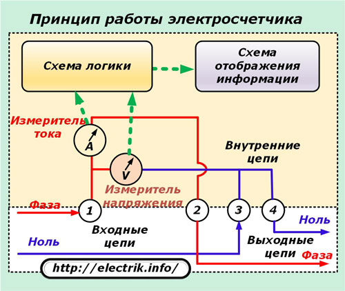
The principle of operation of any counter can be represented in a simplified block diagram, consisting of:
input and output circuits;
internal schema.
Electrical energy meters are divided into two large groups operating in networks:
1. alternating voltage of industrial frequency;
2. DC.
AC electricity meters
This class of counters is divided into three types according to the design:
1. induction, working since the end of the nineteenth century;
2. electronic devices that appeared not so long ago;
3. hybrid products that combine digital technologies in their design with an induction or electric measuring part and a mechanical counting device.
Induction meters
The principle of operation of such a counter is based on the interaction of magnetic fields. generated by electromagnets of a current coil embedded in the load circuit, and a voltage coil connected in parallel to the supply voltage circuit.
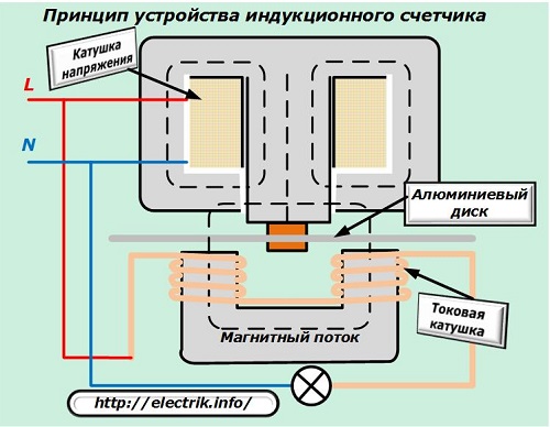
They create a total magnetic flux proportional to the value of the power passing through the meter. In the field of its action is a thin aluminum disk mounted in a rotation bearing. It reacts to the magnitude and direction of the generated force field and rotates around its own axis.
The speed and direction of movement of this disk correspond to the value of the applied power. A kinematic diagram is connected to it, consisting of a system of gears and wheels with digital indicators that indicate the number of revolutions completed, acting as a simple counting mechanism.
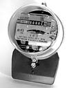
Single-phase induction meter, device features
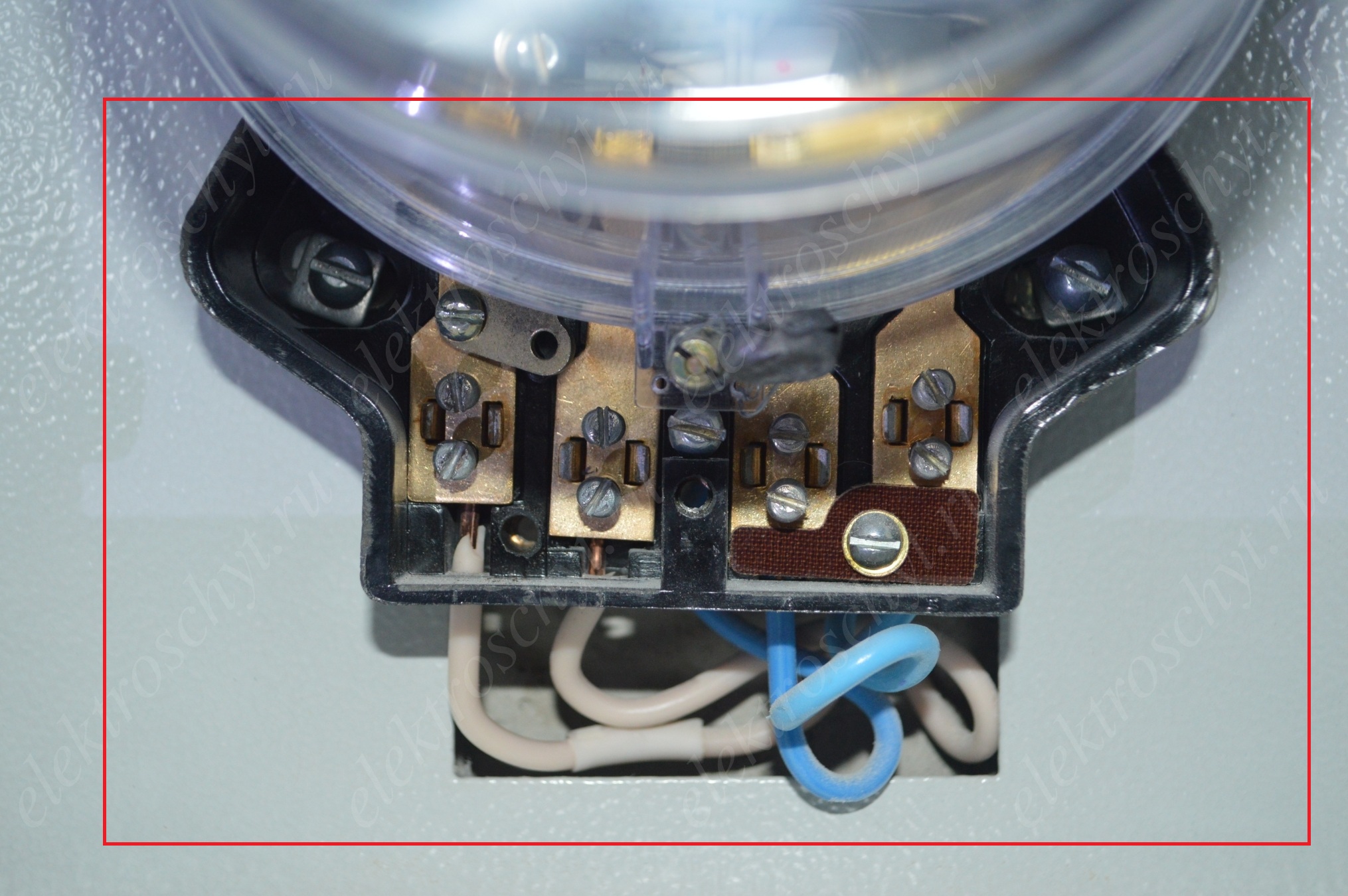
The design of the most common induction meter, designed for single-phase network AC power is shown exploded in the picture, which consists of two combined photos.
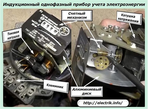
All main technological units are indicated by signs, and circuit diagram internal connections, input and output circuits is shown in the following picture.
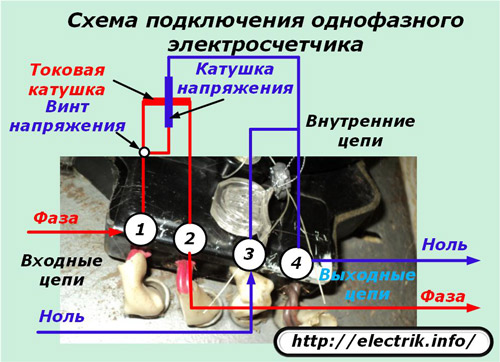
The voltage screw installed under the cover must always be tightened during the operation of the meter. It is used only by employees of electrical laboratories when performing special technological operations - checking the device.
The device, principle of operation and features of the operation of electric meters were previously described here:
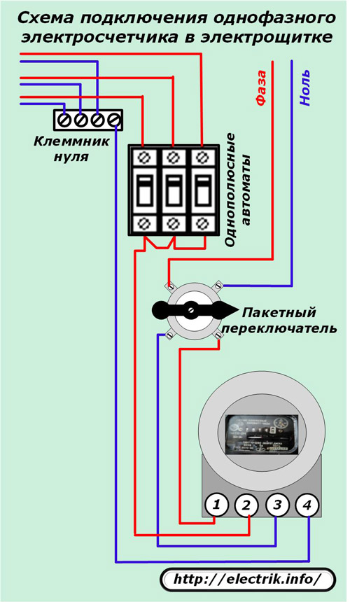
Electric induction meters of this type are successfully completing their resource in residential buildings and apartments of people. They are connected to electrical panels standard scheme through single-pole circuit breakers and package switch.
Design features of a three-phase induction meter
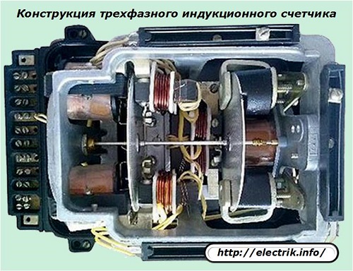
The device of this measuring instrument fully corresponds to single-phase models, except that the formation of the total magnetic flux that affects the rotation of the aluminum disk involves magnetic fields, created by the coils of currents and voltages of all three phases of the power supply circuit of the power circuit.
Due to this, the number of parts inside the case is increased, and they are denser. The aluminum rim is also doubled. The connection scheme for the current and voltage coils is carried out according to the previous connection option, but taking into account the provision of the summation of magnetic fluxes from each individual one.
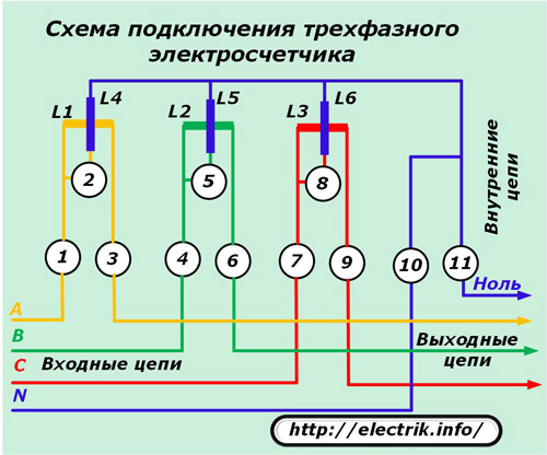
The same effect can be achieved if, instead of one three-phase meter, single-phase devices are included in each phase of the system. However, in this case, you will need to manually add their results. In a three-phase induction meter, this operation is automatically performed by one counting mechanism.
Three-phase induction meters can be made in two types for connection:
1. immediately to the power circuits, the power of which must be taken into account;
2. through intermediate voltage and current measuring transformers.
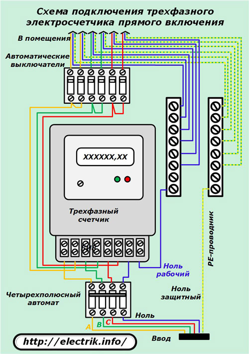
Devices of the first type are used in power circuits of 0.4 kV with loads that cannot cause harm to the metering device with their small amount. They work in garages, small workshops, private houses and are called direct connection meters.
Switching scheme electrical circuits a similar device in the electrical panel is shown in the next picture.
All other induction metering devices work directly through measuring current or voltage transformers separately, depending on the specific conditions of the power supply system, or with their joint use.
The appearance of the scoreboard of an old induction meter of this type (SAZU-IT) is shown in the photograph.
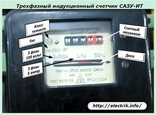
It works in secondary circuits with measuring current transformers with a nominal value of 5 amperes and voltage transformers - 100 volts between phases.
The letter "A" in the name of the device type "SAZU" means that the device is designed to take into account the active component of the total power. Measurements of the reactive component are carried out by other types of devices that have the letter “P” in their composition. They are designated by the type "SRZU-IT".
The above example with the designation of three-phase induction meters indicates that their design cannot take into account the amount of total power expended on doing work. To determine its value, it is necessary to take readings from active and reactive energy metering devices and perform mathematical calculations using prepared tables or formulas.
This process requires the participation of a large number of people, does not exclude common mistakes, labor intensive. New technologies and metering devices operating on semiconductor elements relieve it of its implementation.
Old induction-type meters have practically ceased to be produced on an industrial scale. They simply modify their resource as part of operating electrical equipment. They are no longer used at the newly assembled and put into operation complexes, but new, modern models are installed.
Electronic metering devices
To replace induction-type meters, many electronic devices are now being produced designed to work in home network or as part of measuring complexes of complex industrial equipment that consumes enormous power.
In their work, they constantly analyze the state of the active and reactive components of the total power on the basis of vector diagrams of currents and voltages. According to them, the total power is calculated, and all values \u200b\u200bare entered into the memory of the device. From it, you can view this data at the right time.
Two types of common electronic accounting systems
According to the type of measurement of composite input quantities, electronic type meters produce:
with built-in measuring current and voltage transformers;
with measuring sensors.
Devices with built-in instrument transformers
principled structural scheme an electronic single-phase meter is shown in the picture.
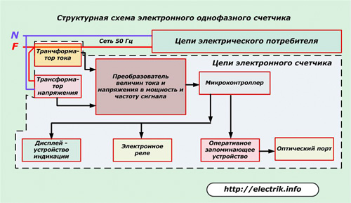
The microcontroller processes the signals coming from the current and voltage transformers through the converter and issues the appropriate commands to:
display with information display;
an electronic relay that switches the internal circuit;
random access memory device RAM, which has an information connection with an optical port for transmission technical parameters through communication channels.
Devices with built-in sensors
This is a different design of the electronic meter. Her circuit works based on sensors:
current, consisting of an ordinary shunt through which the entire load of the power circuit flows;
voltage, working on the principle of a simple divider.
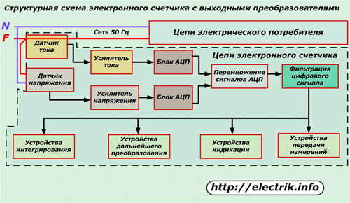
The current and voltage signals coming from these sensors are very small. Therefore, they are reinforced with a special device based on high-precision electronic circuit and served on the blocks of amplitude-digital conversion. After them, the signals are multiplied, filtered and output to the appropriate devices for integration, indication, transformation and further transmission to various users.
Meters operating on this principle have a slightly lower accuracy class, but they fully meet technical standards and requirements.
The principle of using current and voltage sensors instead of measuring transformers makes it possible to create metering devices for this type of circuits not only for alternating current, but also for direct current, which greatly expands their operational capabilities.
On this basis, meter designs began to appear that can be used in both types of DC and AC power supply systems.
Tariff modern appliances accounting
Due to the possibility of programming the operation algorithm, the electronic meter can take into account the power consumption by time of day. Due to this, the interest of the population is created to reduce electricity consumption during the most intense peak hours and thereby relieve the load created for energy supply organizations.
Among electronic metering devices there are models with different capabilities of the tariff system. The greatest abilities are possessed by meters that allow you to flexibly reprogram the counting device for changing tariffs of electric networks, taking into account the time of year, holidays, and various discounts on weekends.
The operation of electricity meters according to the tariff system is beneficial for consumers - money is saved for paying for electricity and for supplying organizations - the peak load is reduced.
See also on this topic:
Design features of industrial metering devices for high-voltage circuits
As an example of such a device, consider the Belarusian counter of the Gran-Electro SS-301 brand.
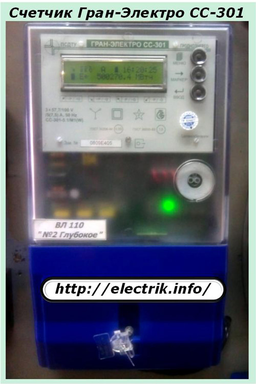
It has many useful features for users. Like ordinary household metering devices, it is sealed and undergoes periodic verification of readings.
There are no moving mechanical elements inside the case. All work is based on the use of electronic boards and microprocessor technologies. Measuring transformers are engaged in the processing of current input signals.
With these devices, special attention is paid to the reliability of operation and the protection of information security. In order to preserve it, the following is introduced:
1. two-level sealing system for internal boards;
2. A five-level scheme for organizing access to passwords.
The filling system is carried out in two steps:
1. access to the inside of the case of this meter is limited immediately at the factory after the completion of its technical tests and the end of the state verification with the execution of the protocol;
2. access to the connection of wires to the terminals is blocked by representatives of the energy supervision or the energy supply company.
Moreover, in the algorithm of the device operation there is a technological operation that records in the electronic memory of the device all events associated with the removal and installation of the terminal cover with an exact binding by date and time.
Scheme for organizing access to passwords
The system allows you to differentiate the rights of the device users, to separate them according to the possibilities of access to the meter settings by creating levels:
zero, providing the removal of restrictions on viewing data locally or remotely, time synchronization, correction of readings. The right is granted to users authorized to work with the device;
the first, which allows you to perform equipment adjustment at the installation site and write to the RAM the settings of operating parameters that do not affect the characteristics of commercial use;
the second, allowing access to the information of the device to representatives of energy supervision after its adjustment and preparation for commissioning;
the third, giving the right to remove and install the cover from the terminal block to access the clamps or the optical port;
the fourth, which provides access to the device boards for installing or replacing hardware keys, removing all seals, performing work with the optical port, upgrading the configuration, and calibrating correction factors.
Ways to connect industrial meters at energy enterprises
For the operation of metering devices, branched secondary circuits of measuring circuits are created through the use of high-precision current and voltage transformers.
A small fragment of such a circuit for the current circuits of the Gran-Electro SS-301 meter is shown in the picture. It is taken from the working documentation.
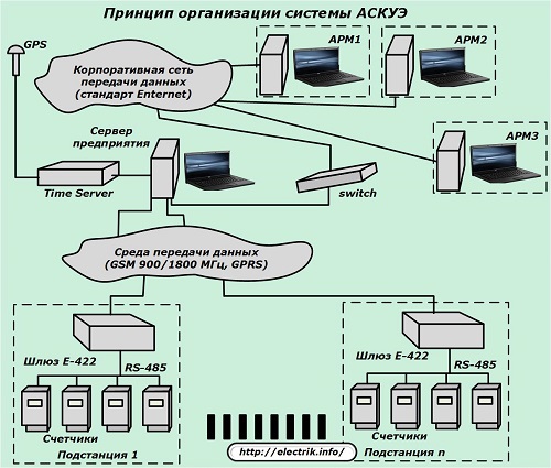
The main task of the ASKUE system is the rapid collection of information in a single control center. At the same time, it receives data streams from all consumers of operating substations. They contain information on the issues of consumed and supplied power with the possibility of analyzing the methods of its generation and distribution, calculating the cost and accounting for economic indicators.
To solve organizational issues of the ASKUE system, the following is provided:
installation of high-precision metering devices in places of electricity metering;
the transfer of information from them is carried out by digital signals using "adders" with RAM;
organization of a communication system via wire and radio channels;
implementation of the scheme for processing the received information.
DC electricity meters
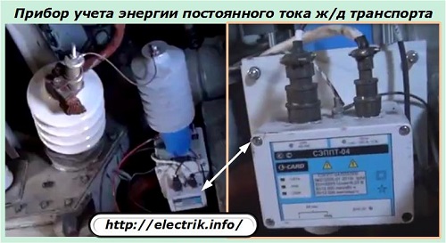
Models of meters of this class record energy in different technological modes, but most often they are used on the equipment of electric rolling stock of urban transport and on railways.
They are created on the basis of an electrodynamic system.
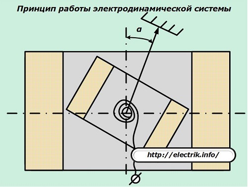
The basic principle of operation of such meters is the interaction of the forces of magnetic fluxes formed by two coils:
1. the first is fixed permanently;
2. the second one has the ability to rotate under the influence of magnetic flux forces, the magnitude of which depends proportionally on the value of the current flowing through the circuit.
The coil rotation parameters are transmitted to the counting mechanism and are taken into account by the consumption of electrical energy.
CLASSIFICATION AND TECHNICAL CHARACTERISTICS OF METERS
There are single-phase and three-phase meters. Single-phase meters are used to account for electricity from consumers who are powered by single-phase current(mostly domestic). For electricity metering three-phase current three-phase meters are used.
Three-phase meters can be classified as follows.
According to the type of measured energy - to active and reactive energy meters.
Depending on the power supply scheme for which they are intended, they are divided into three-wire, operating in a network without a neutral wire, and four-wire, operating in a network with a neutral wire.
According to the method of inclusion, the counters can be divided into
3 groups:
Meters of direct connection (direct connection), are included in the network without measuring transformers. Such meters are produced for 0.4 / 0.23 kV networks for currents up to 100 A.
Meters of indirect connection, with their current windings, are switched on through current transformers. The voltage windings are connected directly to the network. Scope - networks up to 1 kV.
Indirect connection meters are connected to the network through current transformers and voltage transformers. Scope - networks above 1 kV. Two types are produced.
Transformer meters - designed to be switched on through instrument transformers that have predetermined transformation ratios. These counters have a decimal factor (10 n).
Transformer universal meters and - are designed to be switched on through measuring transformers having any transformation ratios. For universal meters, the conversion factor is determined by the transformation ratios of the installed measuring transformers.
Depending on the purpose, the counter is assigned a symbol. In the designations of counters, letters and numbers mean: C - counter; O - single-phase; L -
active energy; P - reactive energy; U - universal; 3 or 4 for a three- or four-wire network. Designation example: SA4U-Three-phase transformer universal four-wire active energy meter.
If the letter M is placed on the meter plate, this means that the meter is designed to work and at negative temperatures(-15°+25°С).
Active and reactive energy meters equipped with additional devices are special purpose meters. Let's list some of them.
Two-tariff meters - are used to account for electricity, the tariff for which varies depending on the time of day.
Prepaid meters - are used to account for electricity of household consumers living in remote and hard-to-reach settlements.
Meters with a maximum load indicator - are used for settlements with consumers at a two-part tariff (for consumed electricity and maximum load).
Telemetering meters - are used for electricity metering and remote transmission of readings.
Special purpose meters also include exemplary meters designed for verification of general purpose meters.
The technical characteristic of the meter is determined by the following main parameters.
Rated voltage and rated current - for three-phase meters, they are indicated as the product of the number of phases and the rated values \u200b\u200bof current and voltage, for four-wire meters, linear and phase voltages. For example - 3x5 A; 3X380/220V.
For transformer meters, instead of the rated current and voltage, the rated transformation ratios of the measuring transformers are indicated, for which the meter is intended, for example: 3 x150/5 A. 3 x6000/100 V.
On counters called overload, the value of the maximum current is indicated immediately after the nominal, for example 5 - 20 A.
The rated voltage of the meters of direct and semi-indirect connection must correspond to the rated voltage of the network, and the meters of indirect connection - to the secondary rated voltage of the voltage transformers.
In the same way, the rated current of the indirect or semi-indirect meter must correspond to the secondary rated current current transformer (5 or 1 A). Counters allow long-term overload but current without violating the correctness of accounting: transformer and transformer universal -120%; direct connection meters - 200% or more (depending on type).
The accuracy class of a meter is its largest allowable relative error, expressed as a percentage. In accordance with GOST 6570-75 * active energy meters must be manufactured with accuracy classes 0.5; 1.0; 2.0; 2.5; reactive energy meters - accuracy classes 1.5; 2.0; 3.0.
Transformer and transformer universal meters for accounting active and reactive energy must be of accuracy class 2.0 and more accurate.
The accuracy class is set for working conditions called normal. These include: direct phase sequence; uniformity and symmetry of loads by phases; sinusoidality of current and voltage (linear distortion factor is not more than 5%); rated frequency (50Hz±0.5%); rated voltage (±1%); rated load; cosφ=1 (for active energy meters) and sinφ= 1 (for reactive energy meters); ambient temperature 20°±3°C (for meters indoor installation); absence of external magnetic fields (induction not more than 0.5 mT); vertical position of the counter.
The gear ratio of the counter is the number of revolutions of its disk, corresponding to the unit of measured energy. For example, 1 kWh is equal to 450 disk revolutions. The gear ratio is indicated on the meter plate.
The meter constant is the value of energy that it measures per 1 rotation of the disc.
- Single-phase induction (electromechanical) electric meter. The device and principle of operation of a single-phase induction meter.
The SO-505 electric meter is a device that records the electricity consumed in a single-phase AC network. Producer - OAO MZEP. To date, this model of an electric meter is quite popular, so below we decided to consider the technical characteristics of the CO-505, operating conditions and the device's switching circuit.
Design features
The SO-505 electric meter (single-phase) refers to induction-type devices, the object of measurement of which is the consumed electricity. The device of the induction measurement system is as follows. The current and voltage coils present in the meter create magnetic fluxes that cross the movable element of the electric meter - a rotating disk, inducing transformation currents in it. These currents create a disk torque proportional to the power drawn by the load. A rotating disk through a system of drive gears causes the rotation of the counting mechanism, on the scale of which the consumed electricity is displayed.
The current coil connected in series with the load is made of copper wire, designed for the maximum operating current of the meter. The voltage coil is connected in parallel and is made with a small cross-section wire.
The whole mechanism is enclosed in a shock-resistant plastic case that does not support combustion. To prevent a situation where electricity can be stolen, the CO-505 electric meter is equipped with a locking device. The stopper prevents the disc from rotating in the opposite direction. Some versions are distinguished by a transparent cover that allows you to see changes in the meter circuit made by an unscrupulous consumer.
The CO-505 has proven to be very reliable and durable despite the presence of moving parts. The electric meter has a service life of 32 years and a calibration interval of 16 years. Specifications, low cost, long service life, verification period, determine the great demand of household consumers for this device.
The disadvantages of the SO-505 electric meter include a low accuracy class, as well as dimensions that exceed electronic counterparts. Currently, the limit for this class of devices is the accuracy class 2.0.
There is a version of SO-505T, which is equipped with a telemetry port designed to transfer information to automated systems, in which the consumed electricity is controlled and taken into account. The design contains an optoelectronic device that counts the number of disk revolutions.
Installation dimensions and dimensions
The drawing shows the overall dimensions that the CO-505 electric meter has:
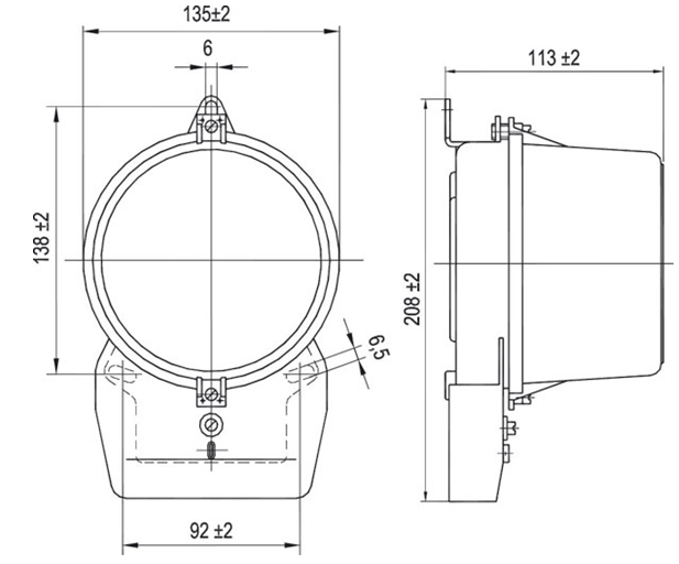
During installation, the meter is fastened with three screws. The SO-505 electric meter is mounted on a vertical surface. Also, deviations from the vertical in the installation plane are not allowed. This is because mechanical system may not work correctly, as a result of which the consumed electricity is reflected unreliably. When the device is skewed, additional braking moments of the disk occur, which can lead to its complete stop.
Specifications
The SO-505 electric meter is designed to work in electrical network voltage 220 volts and frequency 50 hertz. This meter is a direct connection device, that is, the measured electricity is transmitted directly through it. Rated value load current is 10 Amps, maximum admissible current can reach 40 amps. The minimum current at which the meter provides the necessary sensitivity is 0.05 Ampere. The senior category of the counting mechanism has a division value of 10,000 kW * h, the least significant category - 0.1 kW * h. The technical characteristics of the worm-gear transmission provide a change in the scale readings by 1 kWh at 600 revolutions of the disk. The metering device allows operation at a current of 120% of the maximum value for 4 hours.
The electrical power consumed by the CO-505 electric meter during operation is provided below.
Voltage circuits:
- full power - 4.5 V * A;
- active power - 1.3 W.
Current circuits:
- total power - 2.5 V * A.
The electricity consumed by the load connected through the CO-505 meter is measured with the declared accuracy in the supply voltage range from 176 Volts to 254 Volts. The electric meter has a mass of 1.2 kg.
Regarding the operating conditions, this machine is designed to operate at an ambient temperature of -20°C to +55°C.
Switching scheme
The figure shows how to connect the CO-505 electric meter:
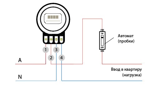
A single-phase meter has four terminals for connecting power wires and loads. Digital marking terminals is shown in the figure. If you place the device facing you, the terminals are numbered from 1 to 4 from left to right.
A phase wire is connected to terminal 1, through which electricity is supplied from the access shield or input to the house. From terminal 2, a phase is entered into the power circuit of an apartment or house. After the meter there is a circuit breaker, a fuse, or a switchboard that divides internal circuit into groups. Terminal 3 is connected to the neutral wire of the power input, terminal 4 is connected to the neutral wire of the input to the apartment or house.
Like( 0 ) I do not like( 0 )
We advise you to read
, diagnosis, treatment Treatment of urogenital chlamydia") Chlamydia urogenital - description, causes, symptoms (signs), diagnosis, treatment Treatment of urogenital chlamydia
Chlamydia urogenital - description, causes, symptoms (signs), diagnosis, treatment Treatment of urogenital chlamydia The benefits and significance of hydroamino acid threonine for the human body L threonine what
 To wait or not to wait for a guy from the army For what reason can they be commissioned from the army
 Baked apples with cottage cheese Baked apples with cottage cheese

