Models differ from each other in terms of rated voltage, resistance and overload. Modern devices are able to work in an economical mode. Ballasts are connected via controllers. As a rule, they are applied electrode type. Also, the connection diagram of the model involves the use of an adapter.
Standard device diagram
Electronic ballast circuits include a set of transceivers. The contacts of the models are of the switched type. A typical device consists of up to 25 pF. Regulators in devices can be used operational or conductor type. Stabilizers in ballasts are installed through the lining. To maintain the operating frequency, the device has a tetrode. The inductor in this case is attached through a rectifier.
Low efficiency devices
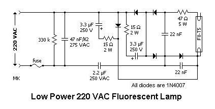
Electronic ballast (circuit 2x36) of low efficiency is suitable for 20 W lamps. Standard scheme includes a set of expansion transceivers. Their threshold voltage is 200 V. The thyristor in devices of this type is used on the lining. The comparator fights overloads. Many models use a converter that operates at a frequency of 35 Hz. A tetrode is used to increase the voltage. Additionally, adapters are used to connect ballasts.
High efficiency devices
The electronic ballast (the connection diagram is shown below) has one transistor with an output to the plate. The threshold voltage of the element is 230 V. For overloads, a comparator is used, which operates on low frequencies. These devices are well suited for lamps up to 25 watts. Stabilizers are often used with variable transistors.
Many circuits use converters, and their operating frequency is 40 Hz. However, it can increase with increasing overloads. It is also worth noting that ballasts use dinistors to rectify the voltage. Regulators are often installed behind transceivers. Operating taxes issue a frequency of no more than 30 Hz.
15 W device
Electronic ballast (2x36 circuit) for 15 W lamps is assembled with integrated transceivers. Thyristors in this case are mounted through a choke. It is also worth noting that there are modifications on open adapters. They are distinguished by high conductivity, but operate at low frequency. Capacitors are only used with comparators. during operation it reaches 200 V. Insulators are used only at the beginning of the circuit. Stabilizers are used with a variable regulator. The conductivity of the element is at least 5 microns.
20 W model
The circuit diagram of the electronic ballast for 20 W lamps implies the use of an expansion transceiver. Transistors are commonly used in different capacities. At the beginning of the circuit, they are set to 3 pF. For many models, the conductivity index reaches 70 microns. In this case, the sensitivity coefficient is not significantly reduced. The capacitors in the circuit are used with an open regulator. The lowering of the operating frequency is carried out through a comparator. In this case, the rectification of the current occurs due to the operation of the converter.
If we consider circuits on phase transceivers, then there are four capacitors. Their capacitance starts at 40 pF. The operating frequency of the ballast is maintained at 50 Hz. Triodes for this are used on operational regulators. To reduce the sensitivity factor, various filters can be found. Rectifiers are quite often used on linings and are installed behind the throttle. The conductance of the ballast primarily depends on the threshold voltage. The type of regulator is also taken into account.

36 W Ballast Schematic
Electronic ballast (2x36 circuit) for 36 W lamps has an expansion transceiver. The device is connected via an adapter. If we talk about the performance of ballasts, then the rated voltage is 200 watts. Insulators for devices are suitable for low conductivity.
Also, the 36W electronic ballast circuit includes capacitors with a capacity of 4 pF. Thyristors are often installed behind filters. To control the operating frequency there are regulators. Many models use two rectifiers. The operating frequency for ballasts of this type is maximum 55 Hz. In this case, the overload can increase significantly.
Ballast T8
The electronic ballast T8 (circuit shown below) has two low conductance transistors. The models use only contact thyristors. There are capacitors at the beginning of the circuit large capacity. It is also worth noting that ballasts are produced on contactor stabilizers. Many models maintain a Heat Loss Coefficient of around 65%. The comparator is set with a frequency of 30 Hz and a conductivity of 4 microns. The triode for it is selected with a lining and an insulator. The device is switched on via an adapter.

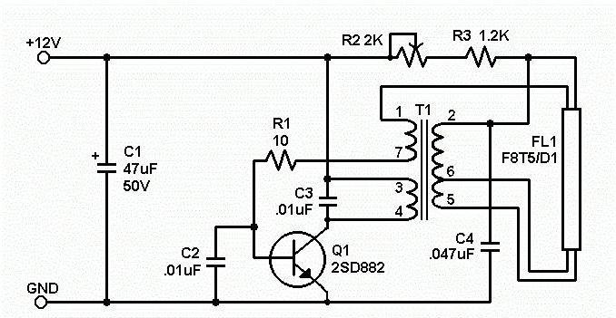
Using transistors MJE13003A
The electronic ballast (2x36 circuit) with MJE13003A transistors includes only one converter, which is located behind the throttle. The models use a variable type contactor. The operating frequency of the ballasts is 40 Hz. In this case, the threshold voltage during overloads is 230 V. The triode is used in devices of the pole type. Many models have three rectifiers with a conductivity of 5 microns. The disadvantage of the device with transits MJE13003A can be considered high heat losses.
Using N13003A transistors
Ballasts with these transistors are valued for good conductivity. They have a low heat loss coefficient. The standard device circuit includes a wire converter. The throttle in this case is used with a lining. Many models have low conductivity, but the operating frequency is 30 Hz. Comparators for modifications are selected on a wave capacitor. Regulators are only suitable for operating type. In total, the device has two relays, and contactors are installed behind the throttle.
The use of transistors KT8170A1
The ballast on the KT8170A1 transistor consists of two transceivers. The models have three filters for impulse noise. The rectifier is responsible for turning on the transceiver, which operates at a frequency of 45 Hz. Models use only variable-type converters. They operate at a threshold voltage of 200 V. These devices are excellent for 15 W lamps. Triodes in controllers are used as output type. The overload indicator may vary, and this is primarily due to the relay capacity. You also need to remember about the capacitance of the capacitors. If we consider wired models, then the above parameter for the elements should not exceed 70 pF.
The use of transistors KT872A
Schematic diagram of the electronic ballast on transistors KT872A involves the use of only variable converters. The bandwidth is about 5 microns, but the operating frequency may vary. The transceiver for ballast is selected with an expander. Many models use several capacitors of different capacities. At the beginning of the chain, elements with plates are used. It is also worth noting that the triode is allowed to be installed in front of the inductor. Conductivity in this case will be 6 microns, and the operating frequency will not be higher than 20 Hz. At a voltage of 200 V, the overload at the ballast will be about 2 A. To solve problems with reduced sensitivity, stabilizers on expanders are used.
The use of single-pole dinistors
An electronic ballast (2x36 circuit) with single-pole dinistors is capable of operating at an overload of more than 4 A. The disadvantage of such devices is a high heat loss coefficient. The modification scheme includes two low conductivity transceivers. For models, the operating frequency is about 40 Hz. The conductors are attached behind the throttle, and the relay is installed only with a filter. It is also worth noting that the ballasts have a conductive transistor.
Capacitor is used low and high capacitance. At the beginning of the circuit, 4 pF elements are used. The resistance in this section is about 50 ohms. It is also necessary to pay attention to the fact that insulators are used only with filters. The threshold voltage for ballasts when turned on is approximately 230 V. Thus, the models can be used for lamps of different power.
Circuit with a bipolar dinistor
Bipolar dinistors primarily provide high conductivity for the elements. Electronic ballast (2x36 circuit) is made with components on switches. In this case, the regulators are used operational type. The standard circuit of the device includes not only a thyristor, but also a set of capacitors. The transceiver is used in this case of a capacitive type, and it has a high conductivity. The operating frequency of the element is 55 Hz.
The main problem of devices is low sensitivity at high overloads. It is also worth noting that triodes can only operate at an increased frequency. Thus, the lamps often flash, and this is caused by overheating of the capacitors. To solve this problem, filters are installed on the ballasts. However, they are not always able to cope with overloads. In this case, it is worth considering the amplitude of the jumps in the network.
The class of gas-discharge light sources, which includes fluorescent lamps, requires the use of special equipment that carries out the passage of an arc discharge inside a sealed glass case.
Its shape is made in the form of a tube. It can be straight, curved or twisted.
The surface of the glass bulb inside is covered with a layer of phosphor, and tungsten filaments are located at its ends. The internal volume is sealed, filled with an inert gas of low pressure with mercury vapor.
The glow of a fluorescent lamp occurs due to the creation and maintenance of an electric arc discharge in an inert gas between the filaments, which operate on the principle of thermionic emission. For its flow through the tungsten wire, an electric current is passed, which heats the metal.
At the same time, a high potential difference is applied between the filaments, which provides the energy for the flow of an electric arc between them. Mercury vapor improves the current path for it in an inert gas environment. The phosphor layer transforms the optical characteristics of the flow of outgoing light rays.
Ensuring the passage of electrical processes inside a fluorescent lamp is engaged in ballasts. It is abbreviated as PRA.
Types of ballasts
Depending on the element base used, ballast devices can be made in two ways:
1. electromagnetic design;
2. electronic unit.
First models fluorescent lamps worked exclusively through the first method. For this they used:
starter;
throttle.
Electronic blocks appeared not so long ago. They began to be produced after the massive, rapid development of enterprises producing a modern assortment of electronic bases based on microprocessor technologies.
Electromagnetic ballasts
The principle of operation of a fluorescent lamp with electromagnetic ballast (EMPR)
The starter start circuit with the connection of an electromagnetic choke is considered traditional, classical. Due to its relative simplicity and low cost, it remains popular and continues to be widely used in lighting schemes.
After submission mains supply voltage is applied to the lamp through the inductor winding and tungsten filaments to. It was created in the form of a small-sized gas-discharge lamp.
The mains voltage applied to its electrodes causes a glow discharge between them, which forms the glow of an inert gas and heats up its environment. The person next to him perceives it, bends. changing its shape, and closes the gap between the electrodes.
In chain electrical circuit a closed circuit is formed and current begins to flow through it, heating the filaments of the fluorescent lamp. Thermionic emission is formed around them. At the same time, the mercury vapor inside the flask is heated.
The resulting electric current reduces the voltage applied from the network to the starter electrodes by about half. The glowing discharge between them decreases, and the temperature drops. The bimetallic strip reduces its bending, breaking the circuit between the electrodes. The current through them is interrupted, and an EMF of self-induction is created inside the inductor. It instantly creates a short-term discharge in the circuit connected to it: between the filaments of a fluorescent lamp.
Its value reaches several kilovolts. It is enough to create a breakdown of an inert gas medium with heated mercury vapor and heated filaments to the state of thermionic emission. An electric arc occurs between the ends of the lamp, which is the source of light.
At the same time, the voltage at the starter contacts is not enough to break through its inert layer and re-close the electrodes of the bimetallic plate. They remain open. The starter does not take part in the further work scheme.
After starting the glow, the current in the circuit must be limited. Otherwise, circuit elements may burn out. This function is also assigned to . Its inductive reactance limits the increase in current, preventing lamp failure.
Connection diagrams for electromagnetic ballasts
Based on the above principle of operation of fluorescent lamps, various connection schemes are created for them through ballasts.
The simplest is to turn on the throttle and starter for one lamp.
With this method, an additional inductive resistance appears in the power circuit. To reduce reactive power losses from its action, compensation is used by including a capacitor at the input of the circuit, which shifts the angle of the current vector in the opposite direction.
If the power of the inductor allows it to be used to operate several fluorescent lamps, the latter are assembled in series chains, and individual starters are used to start each.

When it is required to compensate for the action of inductive resistance, then the same technique is used as before: a compensation capacitor is connected.
Instead of a choke, an autotransformer can be used in the circuit, which has the same inductive reactance and allows you to adjust the output voltage. Compensation for active power losses on the reactive component is carried out by connecting a capacitor.
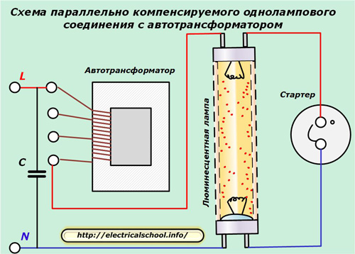
It can be used for lighting with several lamps connected in series.
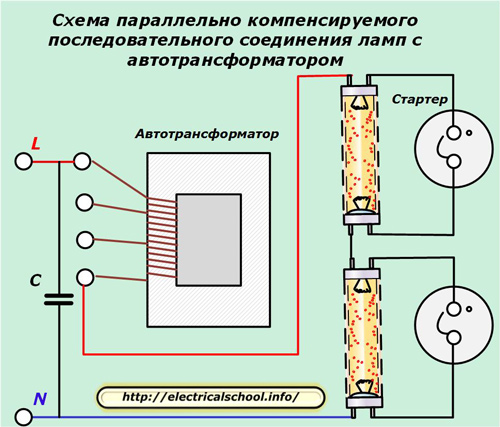
At the same time, it is important to create a reserve of its power to ensure reliable operation.
Disadvantages of operating electromagnetic ballasts
Choke dimensions require the creation of a separate housing for ballasts, which occupies a certain space. At the same time, it emits, albeit a small, but extraneous noise.
The design of the starter is not reliable. Periodically, the lamps go out due to its malfunctions. If the starter fails, a false start occurs, when several flashes can be visually observed before stable combustion begins. This phenomenon affects the life of the filaments.
Electromagnetic ballasts create relatively high energy losses and reduce efficiency.
Voltage multipliers in fluorescent lamp start circuits
This circuit is often found in amateur designs and is not used in industrial designs, although it does not require a complex element base, is easy to manufacture, and is efficient.

The principle of its operation consists in a stepwise increase in the mains supply voltage to significantly higher values, causing a breakdown of the insulation of an inert gas medium with mercury vapor without heating them up and ensuring thermionic emission of filaments.
This connection allows you to use even lamp bulbs with burnt out filaments. To do this, in their scheme, on both sides, the flasks are simply shunted with external jumpers.
Such schemes have heightened danger to hurt a person electric shock. Its source is the voltage coming from the multiplier, which can be increased to a kilovolt or more.
We do not recommend this scheme for use and publish it to explain the dangers of the risks it creates. We focus your attention on this issue specifically: do not use this method yourself and warn your colleagues about this main drawback.
Electronic ballasts
Features of the operation of a fluorescent lamp with electronic ballast (electronic ballast)
All physical laws that occur inside a glass bulb with an inert gas and mercury vapor to form an arc discharge and glow remained unchanged in the designs of lamps controlled by electronic ballasts.
Therefore, the algorithms for the operation of electronic ballasts remained the same as those of their electromagnetic counterparts. just old element base replaced by a modern one.
This ensured not only high reliability of ballasts, but also its small dimensions, allowing it to be installed in any suitable place, even inside the base of a conventional E27 light bulb, developed by Edison for incandescent lamps.
According to this principle, small-sized energy-saving lamps with a fluorescent tube of a complex twisted shape work, which do not exceed incandescent lamps in size and are designed to be connected to the 220 network through old cartridges.
In most cases, for electricians involved in the operation of fluorescent lamps, it is sufficient to provide a simple circuit connection, made with great simplification of several components.
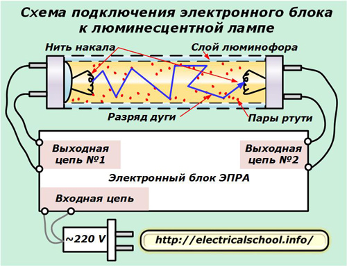
From the electronic ballast for operation stand out:
input circuit connected to a 220 volt power supply;
two output circuits No. 1 and No. 2, connected to the corresponding filaments.
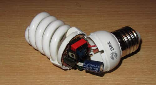
Typically, the electronic unit is made with a high degree of reliability, long service life. In practice, most often energy saving lamps during operation, depressurization of the flask body occurs for various reasons. Inert gas and mercury vapor immediately leave it. Such a lamp will no longer light up, and its electronic unit remains in good condition.
It can be reused, connected to a flask of the appropriate power. For this:
the lamp base is carefully disassembled;
an electronic ballast is removed from it;
mark a pair of wires involved in the power circuit;
mark the conductors of the output circuits on the filament.
Electromagnetic ballast device
Structurally, the electronic unit consists of several parts:
a filter that eliminates and blocks electromagnetic interference coming from the supply network to the circuit or created by the electronic unit during operation;
rectifier of sinusoidal oscillations;
power correction circuits;
smoothing filter;
inverter;
electronic ballast (similar to a throttle).
The electrical circuit of the inverter operates on powerful field-effect transistors and is created according to one of the typical principles: a bridge or half-bridge circuit for switching them on.

In the first case, four keys work in each shoulder of the bridge. Such inverters are designed to convert high power lighting systems into hundreds of watts. The half-bridge circuit contains only two keys, has a lower efficiency, and is used more often.
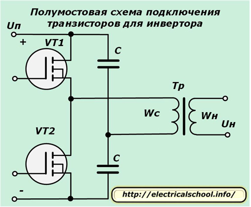
Both circuits are controlled from a special electronic unit - a microdriver.
How electronic gear works
To ensure a reliable glow of a fluorescent lamp, the electronic ballast algorithms are divided into 3 technological stages:
1. preparatory, associated with the initial heating of the electrodes in order to increase thermionic emission;
2. ignition of the arc by applying a high voltage pulse;
3. Ensuring a stable flow of the arc discharge.
This technology allows you to quickly turn on the lamp even when negative temperature, provides a soft start and the issuance of minimal required voltage between the filaments for a good arc glow.
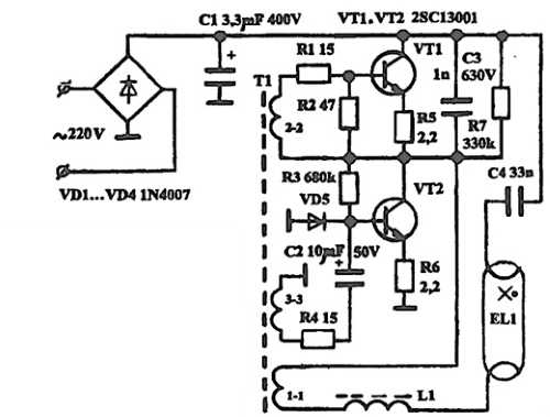
One of the simple circuit diagrams connecting an electronic gear to a fluorescent lamp is shown below.

The diode bridge at the input rectifies AC voltage. Its ripples are smoothed out by capacitor C2. After it, a push-pull inverter connected in a half-bridge circuit works.
It consists of 2 npn transistor that create vibrations high frequency, which are supplied by control signals in antiphase to the windings W1 and W2 of a three-winding toroidal H/h transformer L1. Its remaining winding W3 outputs a high resonant voltage to the fluorescent lamp.
Thus, when the power is turned on, before the lamp starts to ignite, a maximum current is created in the resonant circuit, which provides heating for both filaments.
A capacitor is connected in parallel with the lamp. A large resonant voltage is created on its plates. It starts an electric arc in an inert gas environment. Under its action, the capacitor plates are short-circuited and the voltage resonance is interrupted.
However, the glow of the lamp does not stop. It continues to work automatically due to the remaining share of the applied energy. The inductive reactance of the converter regulates the current passing through the lamp, keeping it in the optimal range.
Light sources, called luminescent, in contrast to their counterparts equipped with a filament, need starting devices called ballast to work.
Ballast for LDS (lamps daylight) belongs to the category of ballasts that are used as a current limiter. The need for them arises if the electrical load is not enough to effectively limit the current consumed.
An example is a conventional light source that belongs to the category of gas-discharge. It is a device with negative resistance.
Depending on the implementation, the ballast may be:
- normal resistance;
- capacitance (having reactance), as well as a choke;
- analog and digital circuits.
Consider the implementation options that have received the greatest distribution.
Ballast types
The most widely used electromagnetic and electronic implementation of the ballast. Let's talk in detail about each of them.
Electromagnetic implementation
This option is based on inductive reactance choke (it is connected in series with the lamp). The second necessary element is the starter, which regulates the process necessary for "ignition". This element is a compact-sized lamp belonging to the gas discharge category. Inside her flask there are electrodes made of bimetal (it is allowed to make one of them bimetallic). Connect the starter in parallel to the lamp. The two options are shown below.
The work is carried out according to the following principle:
- when voltage is applied inside the starter lamp, a discharge is produced, which leads to heating of the bimetallic electrodes, as a result of which they close;
- the short circuit of the starter electrodes leads to an increase in the operating current by several times, since it is limited only by the internal resistance of the throttle coil;
- as a result of an increase in the level of the operating current of the lamp, its electrodes are heated;
- the starter cools down, and its bimetal electrodes open;
- opening the circuit with the starter leads to the appearance of a high voltage pulse in the inductor coil, due to which a discharge occurs inside the source bulb, which leads to its “ignition”.
After the lighting device switches to normal operation, the voltage on it and the starter will be less than the mains by about half, which is not enough to operate the latter. That is, it will be in the open state and will not affect the further operation of the lighting device.
This type of ballast is easy to implement and low cost. But we should not forget that this version of ballasts has a number of disadvantages, such as:
- it takes from one to three seconds to "ignite", and, during operation, this time will steadily increase;
- sources with electromagnetic ballast flicker during operation, which causes eye fatigue and can cause headaches;
- the power consumption of electromagnetic devices is much higher than that of electronic counterparts;
- during operation, the throttle emits a characteristic noise.
These and other shortcomings of electromagnetic starting devices for LDS have led to the fact that at present such ballasts are practically not used. They were replaced by "digital" and analog electronic ballasts.
Electronic implementation
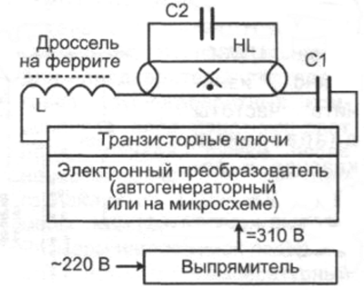
An electronic type ballast, in essence, is a voltage converter with which the LDS is powered. An image of such a device is shown in the picture.
There are many options for the implementation of electronic ballasts. It is possible to imagine a common characteristic for many devices of this type block diagram, which, with few exceptions, is used in all electronic ballasts. Her image is shown in the figure.

Many manufacturers add a power factor correction unit to the device, as well as a brightness control circuit.
There are two most common ways to launch LDS sources using an electronic ballast implementation:
- before applying the ignition potential to the LDS cathodes, they are preliminarily subjected to heating. Due to the high frequency of the incoming voltage, two goals are achieved: a significant increase in efficiency and the elimination of flicker. Note that depending on the design of the ballast, ignition can be instantaneous or gradual (that is, the brightness of the source will gradually increase);
- combined method, it is characterized by the fact that an oscillatory circuit takes part in the “ignition” process, which must enter into resonance before a discharge occurs in the LDS flask. During resonance, there is an increase in the voltage supplied to the cathodes, and an increase in current ensures their heating.
In most cases, with the combined start-up method, the circuit is implemented in such a way that the filament of the LDS cathode (after serial connection through the capacitance) is part of the circuit. When a discharge occurs in a gaseous medium luminescent source, this leads to a change in the parameters of the oscillatory circuit. As a result, it goes out of resonance. Accordingly, there is a voltage drop to the normal mode. An example diagram of such a device is shown in the figure.
In this circuit, the oscillator is built on two transistors. Power is supplied to the LDS from winding 1-1 (which is step-up for the Tr transformer). At the same time, such elements as capacitance C4 and inductor L1 are a series oscillatory circuit, with a resonant frequency different from that generated by the oscillator. Similar electronic ballast circuits are common in many budget table lamps.
Video: how to make a ballast for lamps
Speaking of electronic ballast, one cannot but mention the compact LDS, which are designed for standard E27 and E14 cartridges. In such devices, the ballast is built into the overall design.
As an implementation example, the ballast diagram of an energy-saving Osram LDS with a power of 21W is shown below.

It should be noted that due to the design features, serious requirements are imposed on the electronic elements of such devices. In products of unknown manufacturers, a simpler element base can be used, which becomes common cause failure of compact LDS.
Advantages
Electronic devices have many advantages over electromagnetic ballasts, we list the main ones:
- electronic ballasts do not cause flickering of the LDS during its operation and do not create extraneous noise;
- the circuit on electronic elements consumes less energy, weighs lighter and is more compact;
- the possibility of implementing a circuit that produces a "hot start", in this case, the LDS cathodes are preheated. Thanks to this switching mode, the service life of the source is significantly extended;
- an electronic ballast does not need a starter, since it is itself responsible for generating the voltage levels necessary for start and operation.
A fluorescent lamp (LL) is a light source from a sealed glass bulb, inside which an electric electrode discharge is created, flowing in a gaseous medium. On its inner surface there is a phosphorus-containing layer (phosphor). Inside the lamp is an inert gas and 1% mercury vapor. When exposed to an electric discharge, they emit visually invisible ultraviolet light, which causes the phosphor to glow.
Ballasts for fluorescent lamps
If even one fluorescent lamp breaks in a room, mercury vapor will exceed the permissible values by 10 times. Her bad influence stored for 1-2 months.
Application
The electrically conductive gaseous medium inside fluorescent lamps has a negative resistance, which manifests itself in the fact that with increasing current, the voltage between the electrodes decreases.

Scheme of operation of a fluorescent lamp
Therefore, a current limiter LL1 is connected to the circuit - a ballast, as can be seen from the figure. The device also serves to create a short-term overvoltage ignition of lamps, which is not enough in the current network. It is also called a choke.
The ballast also contains a small glow lamp E1 - starter. Inside it there are 2 electrodes, one of which is movable, it is made of a bimetallic plate.
In the initial state, the electrodes are open. When the mains voltage is applied to the circuit by closing the SA1 contact at the initial moment, no current passes through the fluorescent lamp, and a glow discharge is formed inside the starter between the electrodes. The electrodes heat up from it, and the bimetallic plate bends, closing the contact inside the starter. As a result, the current through the LL1 ballast increases and heats up the electrodes of the fluorescent lamp.
After the circuit, the discharge inside the starter E1 stops, and the electrodes begin to cool. In this case, they open, and as a result of self-induction, the inductor creates a significant voltage pulse that ignites the LL. At the same time, a current equal in magnitude to the nominal current begins to pass through it, which then decreases by 2 times due to the voltage drop across the inductor. This current is not enough to create a glow discharge in the starter, so its electrodes remain open while the fluorescent lamp is on. Capacitors C1 and C2 allow you to reduce reactive loads and increase efficiency.
Electromagnetic choke
The ballast limits the current flow. Part of the power heats up the device, which leads to energy losses. In terms of loss levels, the ballast for lamps can be as follows:
- D - normal;
- C - reduced;
- B - especially low.
When the ballast is connected to the network, the alternating voltage leads the current in phase. Its designation always indicates the cosine of the angle of this lag, called the power factor. The smaller its value, the more reactive energy is consumed, which is an additional load. To increase the power factor to a value of 0.85, a capacitor with a capacitance of 3-5 microfarads is connected in parallel with the network.
Any electromagnetic choke creates noise. Depending on how much it can be reduced, ballasts are produced with normal (N), low (P), very low (C, A) noise levels.
The power of lamps and ballasts must be selected in accordance with each other (from 4 to 80 W), otherwise the lamp will fail prematurely. They are supplied in a kit, but you can choose your own.
The classic starting device from an electromagnetic ballast and a starter (EMPRA) has the following advantages:
- relative simplicity;
- high reliability;
- small price;
- no repairs are required, because even with your own hands it will cost more than buying a new unit.
In addition, it has a whole host of disadvantages:
- long start;
- energy losses (up to 15%);
- noise during throttle operation;
- large dimensions and weight;
- unsatisfactory start at low ambient temperature;
- blinking lamp.
The shortcomings of the chokes led to the need to create a new device. Electronic ballast is an innovative solution that improves the quality of LL operation and makes it durable. The electronic ballast circuit (electronic ballast) is a single electronic unit that forms the sequence of voltage changes for ignition.
Block diagram for starting lamps with electronic ballasts
The advantages of electronic circuits are as follows:
- start can be instantaneous and with a delay;
- no need for a starter to start;
- due to the high frequency, there is no “blinking”, and the light output is higher;
- the design is lighter and more compact;
- durability due to optimal start-up and operation modes.
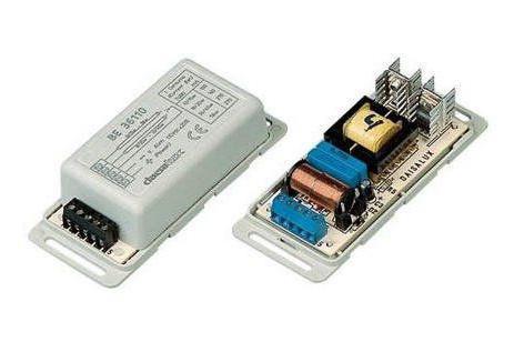
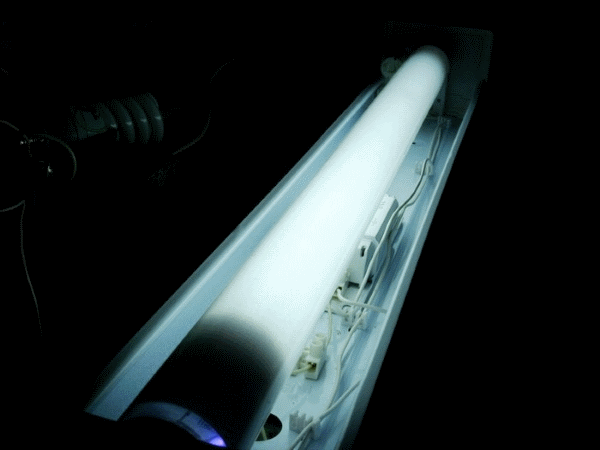
Externally, the electronic ballast looks as shown in the figure below.

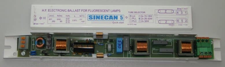
Electronic ballasts for fluorescent lamps
The disadvantage of electronic ballasts is the high price due to the complexity of the circuit.
Running lamps
The electrodes of the lamp are heated, after which they are supplied with high voltage through the control device. Its frequency is 20-60 kHz, which makes it possible to eliminate flicker and increase efficiency. Depending on the scheme, the launch can be instant or smooth - with an increase in brightness to the working one.
With a cold start, the service life of fluorescent lamps is significantly reduced.
An oscillatory circuit in the lamp power circuit is added to the process of heating the electrodes, which enters into electrical resonance before the discharge. In this case, the voltage increases significantly, the cathodes are heated more intensively, and as a result, ignition occurs easily. As soon as the discharge in the lamp begins, the oscillatory circuit immediately goes out of resonance and the operating voltage is established.
For cheap electronic ballasts or self-assembled ones, the principle of operation is similar to the choke option: the lamps are ignited with a high voltage, and the discharge is held with a small one.
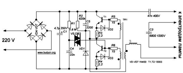
Diagram of electronic ballast
As in all electronic ballast circuits, the voltage is rectified by diodes VD4-VD7, which is then filtered by capacitor C1. The filter capacitance is selected at the rate of 1 uF per 1 W of lamp power. With smaller capacitor values, the glow will be dimmer.
As soon as the connection to the network occurs, the capacitor C4 immediately begins to charge. When 30 V is reached, the dinistor CD1 breaks through and the transistor T2 opens with a voltage pulse, then the half-bridge oscillator of transistors T1, T2 and the transformer TR1 with two out-of-phase primary and one secondary windings. The resonant frequency of the series circuit of capacitors C2, C3, inductor L1 and the generator are close in magnitude (45-50 kHz). When the voltage on capacitor C3 rises to the start value, the lamp lights up. This reduces the generator frequency and voltage, and the inductor limits the current. Due to the high frequency, its dimensions are small.
Faults and repairs
Burnt parts in the circuit are often visible. How to check the electronic ballast? Most often, transistors fail. A burnt part can be detected visually. When doing do-it-yourself repairs, it is recommended to check the transistor paired with it and the resistors located nearby. Burnt ones are not always visible on them. A swollen capacitor must be replaced. If there are several burnt parts, the ballast is not repaired.
Sometimes after turning off the electronic ballast, the lamp continues to flicker weakly. One of the reasons may be the presence of potential at the input when zero is turned off. The circuit must be checked and connections made by oneself so that the switch is set to phase. It is possible that a charge remains on the filter capacitor. Then it should be connected in parallel to the resistance for discharging at 200-300 kOhm.
Due to power surges, it is often necessary to repair luminaires with electronic ballast. With an unstable power supply, it is better to use an electromagnetic choke.
A compact lamp (CFL) contains an electronic ballast built into the base. LL repair of low price and quality is carried out for the following reasons: burning of a filament, breakdown of transistors or a resonant capacitor. If the spiral burned out, do-it-yourself repairs will briefly extend the service life and it is better to replace the lamp. It is also not advisable to repair LLs in which the phosphor layer is burned (blackening of the bulb in the area of the electrodes). In this case, a serviceable ballast can be used as a spare.
Burning of the phosphor on a fluorescent lamp
Repair of the electronic ballast will not be required for a long time if you upgrade the CFL by installing an NTS thermistor (5-15 Ohm) in series with the resonant capacitor with your own hands. The part limits the starting current and protects the filaments for a long time. It is also advisable to make ventilation holes in the plinth.

Do-it-yourself ventilation device for heat removal from ballast
Holes are carefully drilled next to the tube for better cooling, as well as near the metal part of the base to remove heat from the ballast parts. Such repairs are possible only in dry rooms. In the middle, you can make a third row of holes with a larger diameter drill.
Repair with the installation of a thermistor is carried out with soldering the conductor on the bottom platform with solder. Then the convex part of the base is bent from the glass bulb and the second wire is released. After the plinth is removed and access to printed circuit board. After the repair is completed, the base is installed in the reverse order.
DIY
Tubular LLs with a length of 1200 mm are inexpensive and can illuminate large areas. The lamp can be made by hand, for example, from 2 lamps of 36 W each.
- The body is a rectangular base made of non-combustible material. You can use a used lamp, for which repair is no longer required.
- ECG is selected according to the power of the lamps.
- For each of the lamps you will need 2 G13 cartridges, stranded wire and fixture.
- Sockets for lamps are mounted on the body after choosing the distance between them.
- The electronic ballast is installed in the zone of minimum heating from the lamps (usually closer to the center) and is connected to the cartridges. Each block is produced with a wiring diagram on the case.
- The luminaire is mounted on a wall or ceiling and is connected to a 220 V power supply through a switch.
- To protect the lamps, it is desirable to use a transparent cap.
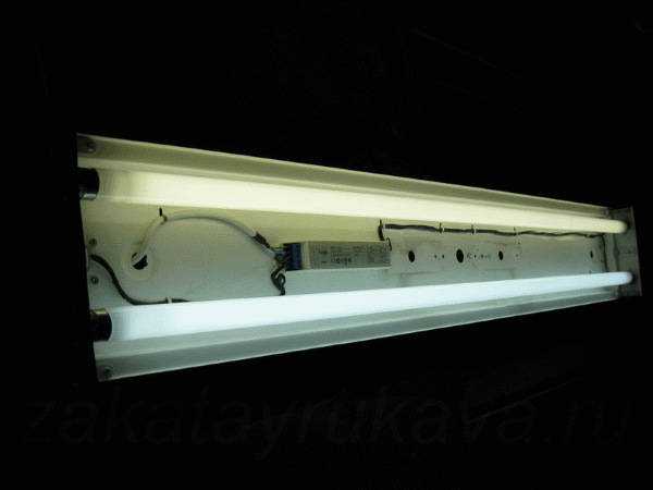
Homemade lamp
Replacement. Video
How to replace the electronic ballast in the lamp, this video will clearly tell.
LL should be fed with high frequency current, for which an electronic ballast is well suited. They contain little mercury vapor; here, heating of the filaments normalized in time and current is required to enter the operating mode.


