For the amount of torque induction motor the phase shift between the current I 2 and e has a great influence. d.s. E 2S rotor.
Consider the case when the inductance of the rotor winding is small and therefore the phase shift can be neglected (Fig. 223, a).
The rotating magnetic field of the stator is here replaced by the field of the N and S poles, rotating, let's say, in a clockwise direction. Using the rule of the right hand, we determine the direction e. d.s. and currents in the rotor winding. The rotor currents, interacting with the rotating magnetic field, create a torque. The directions of the forces acting on current-carrying conductors are determined by the left-hand rule. As can be seen from the drawing, the rotor under the action of forces will rotate in the same direction as the rotating field itself, that is, clockwise.
Consider the second case, when the inductance of the rotor winding is large. In this case, the phase shift between the rotor current I 2 and e. d.s. rotor E 2S will also be large. In FIG. 223, b, the magnetic field of the stator of an induction motor is still shown in the form of clockwise rotating poles N and S. The direction of e. d.s. remains the same as in Fig. 223, a, but due to the delay of the current in phase, the axis magnetic field the rotor will no longer coincide with the neutral line of the stator field, but will shift by some angle against the rotation of the magnetic field. This will lead to the fact that along with the formation of a torque directed in one direction, some conductors will create an opposite torque.
It can be seen from this that the total torque of the motor during a phase shift between current and e. d.s. the rotor is smaller than for the case when I 2 and E 2S are in phase. It can be proved that the torque of an induction motor is determined only by the active component of the rotor current, i.e. current I 2 cos and that it can be calculated by the formula:
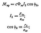
Ф m - stator magnetic flux (and also approximately equal to the resulting magnetic flux of the induction motor);
Phase angle between e. d.s. and winding phase current
C is a constant coefficient.
After substitution:
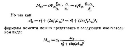
From the last expression it can be seen that the torque of the induction motor depends on the slip.
In FIG. 224 shows curve A of motor torque versus slip. It can be seen from the curve that at the moment of starting, when s=l and n = 0, the motor torque is small. This is explained by the fact that at the moment of starting, the frequency of the current in the rotor winding is the highest and the inductive resistance of the winding is large. As a result, cos has a small value (because
|
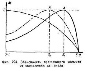
row 0.1-0.2). Therefore, although the starting current is large, the starting torque will be small.
With some slip S 1, the motor torque will have a maximum value. With a further decrease in slip, or, in other words, with a further increase in the speed of rotation of the engine, its torque will rapidly decrease.
To stagger and when sliding s = 0, the torque of the engine will also be equal to zero.
It should be noted that in an asynchronous motor, a slip equal to zero cannot practically exist. This is possible only if the rotor is externally supplied with a torque in the direction of rotation of the stator field.
Starting torque can be increased if, at the moment of starting, the phase shift between current and e. d.s. rotor. From the formula
it can be seen that if at a constant inductive reactance windings of the rotor to increase the active resistance, then the angle itself will decrease, which will lead to the fact that the engine torque will also increase. This is used in practice to increase the starting torque of the engine. At the moment of starting, an active resistance (starting rheostat) is introduced into the rotor circuit, which is then removed as soon as the engine increases speed.
Increasing the starting torque causes the maximum torque of the motor to be obtained with more slip (point S 2 of curve B in FIG. 224). By increasing the active resistance of the rotor circuit at start-up, it is possible to achieve that the maximum torque will be at the moment of start-up (s = 1 curve C).
The torque of an induction motor is proportional to the square of the voltage, so even a small decrease in voltage is accompanied by a sharp decrease in torque.
Power P 1 supplied to the stator winding of an induction motor is equal to:
![]()
where m 1 is the number of phases.
The motor stator has the following energy losses:
1) in the stator winding R es. =m 1 I 1 2 r 1 ;
2) in the stator steel and hysteresis and eddy currents P C .
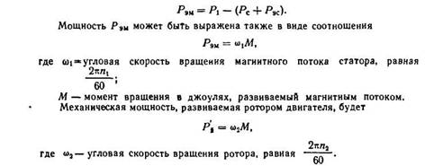
The power supplied to the rotor is the power of the rotating magnetic field, also called the electromagnetic power P eM .
The electromagnetic power is equal to the difference between the power supplied to the motor and the losses in the motor stator, i.e.
|
The difference between Р eM and represents the electrical losses in the rotor winding Р eP, if we neglect the losses in the rotor steel due to their insignificance (the frequency of remagnetization of the rotor is usually very small):
Therefore, the losses in the rotor winding are proportional to the slip of the rotor.
If from mechanical power developed by the rotor, subtract the mechanical losses R mx due to friction in the rotor bearings, friction on air, etc., as well as additional losses R D arising under load and due to rotor stray fields, and losses caused by: magnetic field pulsations in the stator teeth and the rotor, then there will be useful power on the motor shaft, which we denote by P 2 .
The efficiency of an induction motor can be determined by the formula:
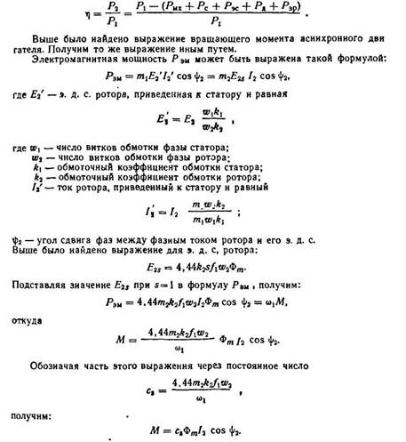
From the last expression it can be seen that the moment of rotation of an induction motor is proportional to the product of the magnitude of the rotating magnetic flux, the rotor current and the cosine of the angle between e. d.s. rotor and its current,
From the equivalent circuit of an asynchronous motor, the value of the reduced rotor current is obtained, which we give without proof.
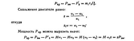
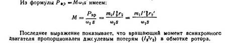
The moment developed by the motor is equal to the electromagnetic power divided by the synchronous speed of rotation of the electric drive.
M \u003d P em / ω 0
Electromagnetic power is the power transmitted through the air gap from the stator to the rotor, and it is equal to the losses in the rotor, which are determined by the formula:
P em \u003d m I 2 2 (r 2 '/s)
m is the number of phases.
M \u003d M em \u003d (Pm / ω 0) (I 2 ') 2 (r 2 '/s)
The electromechanical characteristic of an asynchronous motor is the dependence of I2' on slip. But since asynchronous machine works only as an electric motor, the main characteristic is the mechanical characteristic.
M \u003d Me m \u003d (Pm / ω 0) (I 2 ') 2 (r 2 '/s) - a simplified expression of the mechanical characteristic.
Substituting the current value into this expression, we get: M \u003d / [ω 0 [(r 1 + r 2 '/s) 2 + (x 1 + x 2 ') 2 ]]
Instead of ω 0, you need to substitute the mechanical speed, as a result of which the number of pole pairs is reduced.
M \u003d / [ω 0 [(r 1 + r 2 '/s) 2 + (x 1 + x 2 ') 2 ]] is the equation for the mechanical characteristic of an induction motor.
When the induction motor goes into generator mode, the rotation speed ω > ω 0 and the slip becomes negative (s When the slip changes from 0 to +∞, the mode is called "electromagnetic brake mode".
Given slip values from o to +∞, we obtain the characteristic:
Complete mechanical characteristic of an asynchronous motor.
As can be seen from the mechanical characteristic, it has two extrema: one in the segment of slip change in the area from 0 to +∞, the other in the segment from 0 to -∞. dM/ds=0
M max = / ] + refers to the motor mode. - refers to the generator mode.
M max \u003d M cr M cr - critical moment.
The slip at which the moment reaches its maximum is called critical slip, and it is determined by the formula: s cr = ±
Critical slip has the same value in both motor and generator modes.
The value of M cr can be obtained by substituting the value of the critical slip into the moment formula.
The moment when the slip is equal to 1 is called the starting torque. The expression for the starting torque can be obtained by substituting 1 into the formula:
M p \u003d / [ω 0 [(r 1 + r 2 ’) 2 + (x 1 + x 2 ’) 2 ]]
Since the denominator in the formula for the maximum moment is several orders of magnitude greater than U f, it is customary to consider M kr ≡U f 2 .
Critical slip depends on the value of the active resistance of the rotor winding R 2 '. The starting torque, as can be seen from the formula, depends on the active resistance of the rotor r 2 ’. this property of the starting torque is used in asynchronous motors with a phase rotor, in which the starting torque is increased by introducing active resistance into the rotor circuit.
7. Idling transformer
The idle mode of the transformer is called the mode of operation when one of the transformer windings is powered from a source with alternating voltage and with open circuits of other windings. This mode of operation can be in a real transformer when it is connected to the network, and the load fed from its secondary winding is not yet turned on. By primary winding transformer passes current I 0 , at the same time during secondary winding there is no current, because the circuit is open. Current I 0 , passing through the primary winding, creates a sinusoidally changing tray Ф 0 in the magnetic circuit, which, due to magnetic losses, lags behind the current in phase by a loss angle δ. 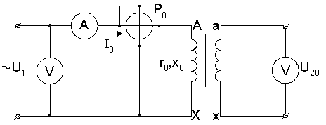
The magnitude of the torque of an induction motor is greatly influenced by the phase shift between the current I 2 and e. d.s. E 2S rotor.
Consider the case when the inductance of the rotor winding is small and therefore the phase shift can be neglected (Fig. 223, a).
The rotating magnetic field of the stator is here replaced by the field of the N and S poles, rotating, let's say, in a clockwise direction. Using the rule of the right hand, we determine the direction e. d.s. and currents in the rotor winding. The rotor currents, interacting with the rotating magnetic field, create a torque. The directions of the forces acting on current-carrying conductors are determined by the left-hand rule. As can be seen from the drawing, the rotor under the action of forces will rotate in the same direction as the rotating field itself, that is, clockwise.
Consider the second case, when the inductance of the rotor winding is large. In this case, the phase shift between the rotor current I 2 and e. d.s. rotor E 2S will also be large. In FIG. 223, b, the magnetic field of the stator of an induction motor is still shown in the form of clockwise rotating poles N and S. The direction of e. d.s. remains the same as in Fig. 223, a, but due to the phase delay of the current, the axis of the magnetic field of the rotor will no longer coincide with the neutral line of the stator field, but will shift by some angle against the rotation of the magnetic field. This will lead to the fact that along with the formation of a torque directed in one direction, some conductors will create an opposite torque.
It can be seen from this that the total torque of the motor during a phase shift between current and e. d.s. the rotor is smaller than for the case when I 2 and E 2S are in phase. It can be proved that the torque of an induction motor is determined only by the active component of the rotor current, i.e. current I 2 cos and that it can be calculated by the formula:
Ф m - stator magnetic flux (and also approximately equal to the resulting magnetic flux of the induction motor);
Phase angle between e. d.s. and winding phase current
C is a constant coefficient.
After substitution:
From the last expression it can be seen that the torque of the induction motor depends on the slip.
In FIG. 224 shows curve A of motor torque versus slip. It can be seen from the curve that at the moment of starting, when s=l and n = 0, the motor torque is small. This is explained by the fact that at the moment of starting, the frequency of the current in the rotor winding is the highest and the inductive resistance of the winding is large. As a result, cos has a small value (because
|
row 0.1-0.2). Therefore, although the starting current is large, the starting torque will be small.
With some slip S 1, the motor torque will have a maximum value. With a further decrease in slip, or, in other words, with a further increase in the speed of rotation of the engine, its torque will rapidly decrease.
To stagger and when sliding s = 0, the torque of the engine will also be equal to zero.
It should be noted that in an asynchronous motor, a slip equal to zero cannot practically exist. This is possible only if the rotor is externally supplied with a torque in the direction of rotation of the stator field.
The starting torque can be increased if, at the moment of starting, the phase shift between current and e is reduced. d.s. rotor. From the formula
it can be seen that if, with a constant inductive resistance of the rotor winding, the active resistance is increased, then the angle itself will decrease, which will lead to the fact that the motor torque will also increase. This is used in practice to increase the starting torque of the engine. At the moment of starting, an active resistance (starting rheostat) is introduced into the rotor circuit, which is then removed as soon as the engine increases speed.
Increasing the starting torque causes the maximum torque of the motor to be obtained with more slip (point S 2 of curve B in FIG. 224). By increasing the active resistance of the rotor circuit at start-up, it is possible to achieve that the maximum torque will be at the moment of start-up (s = 1 curve C).
The torque of an induction motor is proportional to the square of the voltage, so even a small decrease in voltage is accompanied by a sharp decrease in torque.
Power P 1 supplied to the stator winding of an induction motor is equal to:
![]()
where m 1 is the number of phases.
The motor stator has the following energy losses:
1) in the stator winding R es. =m 1 I 1 2 r 1 ;
2) in the stator steel and hysteresis and eddy currents P C .
The power supplied to the rotor is the power of the rotating magnetic field, also called the electromagnetic power P eM .
The electromagnetic power is equal to the difference between the power supplied to the motor and the losses in the motor stator, i.e.
|
The difference between Р eM and represents the electrical losses in the rotor winding Р eP, if we neglect the losses in the rotor steel due to their insignificance (the frequency of remagnetization of the rotor is usually very small):
Therefore, the losses in the rotor winding are proportional to the slip of the rotor.
If from the mechanical power developed by the rotor, subtract the mechanical losses R mx due to friction in the rotor bearings, friction on air, etc. field in the teeth of the stator and rotor, then there will be useful power on the motor shaft, which we denote by P 2.
The efficiency of an induction motor can be determined by the formula:
From the last expression it can be seen that the moment of rotation of an induction motor is proportional to the product of the magnitude of the rotating magnetic flux, the rotor current and the cosine of the angle between e. d.s. rotor and its current,
From the equivalent circuit of an asynchronous motor, the value of the reduced rotor current is obtained, which we give without proof.
We advise you to read
, diagnosis, treatment Treatment of urogenital chlamydia") Chlamydia urogenital - description, causes, symptoms (signs), diagnosis, treatment Treatment of urogenital chlamydia
Chlamydia urogenital - description, causes, symptoms (signs), diagnosis, treatment Treatment of urogenital chlamydia The benefits and significance of hydroamino acid threonine for the human body L threonine what
 To wait or not to wait for a guy from the army For what reason can they be commissioned from the army
 Baked apples with cottage cheese Baked apples with cottage cheese

