If the passport of the electric motor indicates, for example, 220/380 V, this means that the electric motor can be connected both to the 220 V network (the winding connection diagram is a triangle) and to the 380 V network (the winding connection diagram is a star). Stator windings asynchronous motor have 6 ends.
According to GOST, the windings of an asynchronous motor have the following designations: Phase I - C1 (beginning), C4 (end), Phase II - C2 (beginning), C5 (end), Phase III - C3 (beginning), C6 (end).
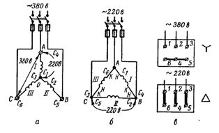
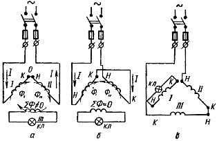
Rice. 1. Wiring diagram of the windings of an asynchronous motor: a - into a star, b - into a triangle, c - implementation of the "star" and "triangle" circuits on the terminal board.
If the voltage in the network is 380 V, then the motor stator windings must be connected according to the "star" scheme. With all this, either all the beginnings (C1, C2, C3) or all the ends (C4, C5, C6) are collected at a common point. A voltage of 380 V is applied between the ends of the windings AB, BC, CA. On each phase, in other words, between the points O and A, O and B, O and C, the voltage will be √3 times less: 380/√3 = 220 V.
Motor Connection Methods
If the voltage in the network is 220 V (with a voltage system of 220/127 V, which is actually nowhere to be found at the current time), the motor stator windings must be connected according to the “triangle” scheme.
At points A, B and C, the beginning (H) of the previous winding with the end (K) of the next winding and with the network phase are connected (Fig. 1, b). If we imagine that phase I is included between points A and B, between points B and C - II, and between points C and A - phase III, then with the "triangle" scheme, the following are connected: the beginning of I (C1) with the end of III (C6) , the beginning of II (C2) with the end of I (C4) and the beginning of III (C3) with the end of II (C5).
For some engines, the ends of the winding phases are brought to the clamp board. According to GOST, the beginnings and ends of the windings are output in the order as shown in Figure 1, c.
If now it is necessary to connect the motor windings according to the “star” scheme, the terminals to which the ends (or beginnings) are connected are closed to each other, and the network phases are connected to the motor terminals to which the beginnings (or ends) are connected.
When connecting the motor windings into a “triangle”, the vertical clamps are connected in pairs and the network phases are connected to the jumpers. Vertical bridges connect the beginning of I with the end of phase III, the beginning of II with the end of phase I, and the beginning of III with the end of phase II.
When determining the winding connection scheme, you can use the following table:
Passport of the electric motor
Determination of coordinated conclusions (beginnings and ends) of the phases of the stator winding.
The terminals of the stator windings of the motor usually have standard designations on iron compression rings. But these compression rings are lost. Then there is a need to find agreed conclusions. They do it in that order.
First, with the help of a test lamp, pairs of leads belonging to individual phase windings are determined (Fig. 2).
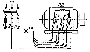
Rice. 2. Determination of phase windings using a test lamp.
One of the 6 terminals of the stator winding of the motor is connected to the network terminal 2, and one end of the test lamp is connected to the other network terminal 3. The other end of the test lamp alternately touches each of the other 5 leads of the stator windings until the lamp lights up. If the lamp lights up, it means that the two outputs connected to the network belong to the same phase.
It is necessary to look with all this so that the conclusions of the windings do not close together. Each pair of conclusions is marked (for example, by tying it in a knot).
Having determined the phases of the stator winding, they proceed to the 2nd part of the work - determining the agreed conclusions or “beginnings” and “ends”. This part of the work can be done in 2 ways.
1. Method of transformation. In one of the phases, a control lamp is turned on. The other two phases are connected in turn and connected to the network for phase voltage.
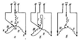
If these two phases turned out to be switched on so that at point O the conditional “end” of one phase is connected to the conditional “beginning” of the other (Fig. 3, a), then the magnetic flux ∑Ф crosses the third winding and induces an EMF in it.
The lamp will indicate the presence of EMF with a small glow. If the glow is invisible, then a voltmeter with a scale of up to 30 - 60 V should be used as an indicator.
Rice. 3. Determination of the beginnings and ends in the phase windings of the motor by the transformation method
If, for example, the conditional “ends” of the windings meet at point O (Fig. 3, b), then the magnetic fluxes of the windings will be oriented back to each other. The total flow will be close to zero, and the lamp will not glow (the voltmeter will show O). In this case, the conclusions belonging to one of the phases should be swapped and turned on again.
If the lamp has a glow (or a voltmeter indicates a certain voltage), then the ends should be marked. On one of the conclusions that met at a common point O, they put on a tag marked H1 (the beginning of phase I), and on the other conclusion - K3 (or K2).
Tags K1 and H3 (or H2) are put on the conclusions that are in common nodes (tied during the first part of the work) with H1 and K3, respectively.
To determine the matched conclusions of the third winding, the circuit shown in Figure 3, c is assembled. The lamp is included in one of the phases already marked with conclusions.
2. Phase selection method. This method for determining the matched conclusions (beginnings and ends) of the phases of the stator winding can be used for small power engines - up to 3 - 5 kW.
Rice. 4. Determination of the "beginnings" and "ends" of the winding by selecting the "star" scheme.
After the conclusions of the individual phases are determined, they are randomly connected into a star (one conclusion from the phase is connected to the network, and one at a time is connected to a common point) and the engine is connected to the network. If all conditional “beginnings” or all “ends” hit a common point, then the engine will work normally.
But if one of the phases (III) turned out to be “inverted” (Fig. 4, a), then the engine is very buzzing, although it can spin (but it can simply be slowed down). In this case, the conclusions of any of the windings at random (for example, I) should be swapped (Fig. 4, b).
If the engine hums again and does not work well, then the phase should be turned on again, as before (as in scheme a), but turn the other phase - III (Fig. 3, c).
If the engine still hums after that, then this phase should also be set as before, and the subsequent phase should be rotated - II.
When the engine starts to work normally (Fig. 4, c), all three outputs that are connected to a common point should be marked identically, for example, with “ends”, and the reverse ones with “beginnings”. After that, you can assemble the working circuit indicated in the motor passport.
Hello, dear visitors and regular readers of the Electrician's Notes website.
I continue the series of articles from the section "". In past articles, I told you about the device, its windings, and conducted an experiment.
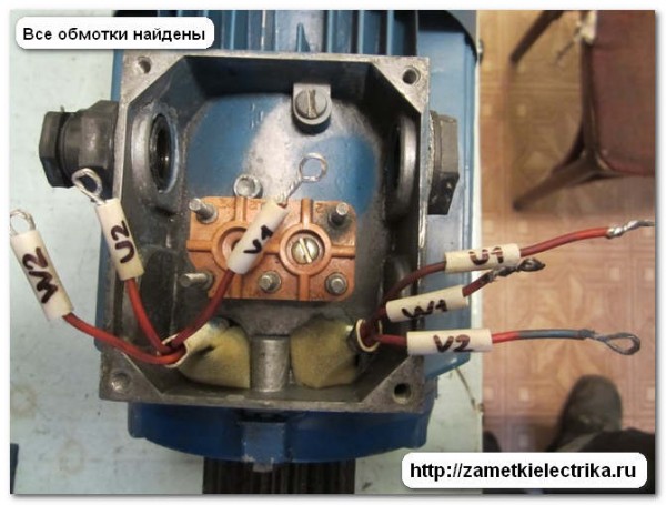
There are situations when you approach the engine in order to connect it to the network, and there are 6 wires in the terminal block, completely without tags and markings.
What to do in such a situation?
This is not very difficult to do. As an example, I will show you clearly how to determine the beginning and end of the windings of the AIR71A4 electric motor.
Step 1
The very first step in determining the beginning and end of the windings induction motor is the writing of labels (cambrics). To do this, use a PVC tube with a diameter of 5 (mm) and a marker.
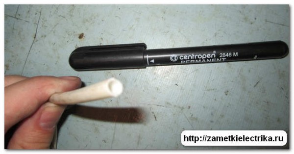
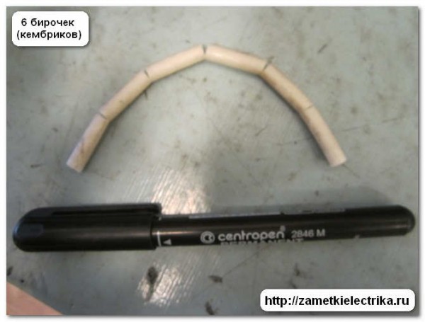
We cut six segments of the same length from the PVC tube and sign them with a marker.
I told you about the marking of the windings of a three-phase asynchronous motor in an article about. Who forgot, then follow the link and read.
Here's what happened.
Step 2
You already know that the stator winding of an induction motor consists of 3 windings shifted relative to each other by 120 electrical degrees. So the second step in determining the beginning and end of the windings of an induction motor is to determine whether all six leads belong to the corresponding windings.
How it's done?
You can use a regular ohmmeter, but I prefer to use a digital multimeter. By the way, an interesting and detailed article will soon be published about how, during the various kinds.
In order not to miss the release of new articles on the site, you need to subscribe to receive news at the end of the article or in the right column of the site.
So, using a multimeter, we determine the first winding. We set the multimeter operation mode switch to position 200 (Ohm).
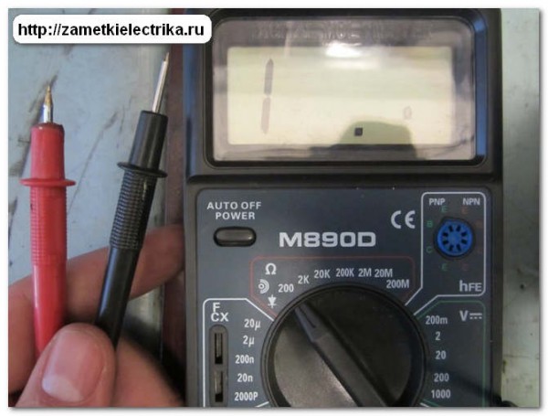
With one probe we stand on any of the six conductors. The second is looking for its end. As soon as we get to the desired conductor, the multimeter readings will show us a value other than zero. In my example, it is 14.7 (Ohm).
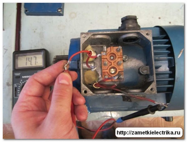
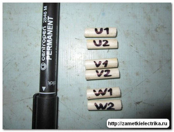
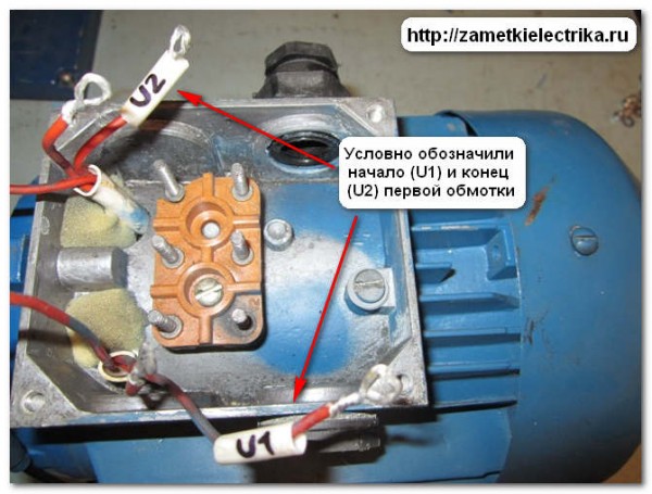
This is the first stator winding of our electric motor. We put U1 and U2 tags on it in random order.
Similarly, we continue to look for the other two windings.
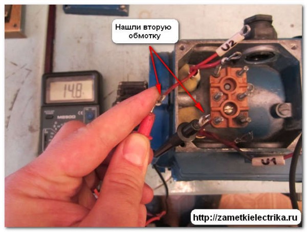
We put tags (cambric) on the found windings, respectively, V1, V2 and W1, W2.
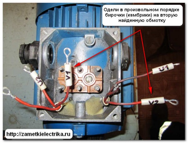
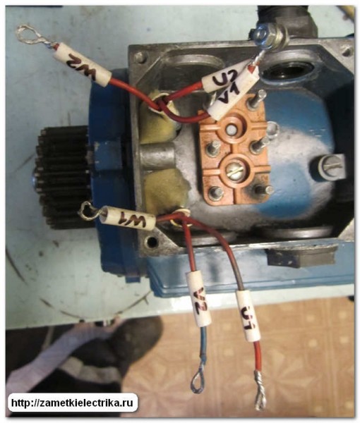
As a result, we get six wires with tags (cambric) put on them in an arbitrary form.
Step 3
To proceed to the third step of determining the beginning and end of the windings three-phase electric motor It is necessary to briefly recall the theory of electrical engineering.
So, two windings located on the same core can be connected either in coordination or in opposite directions.
With the coordinated inclusion of two windings, there will be electromotive force EMF, consisting of the sum of the EMF of the first and second windings. Thus, in these windings, the process of electromagnetic induction occurs, which induces an EMF in a nearby winding, i.e. voltage.
If two windings are connected in opposite directions, then the sum of the EMF of these two windings will be equal to zero, because The EMF of each winding will be directed at each other, and thus cancel each other out. Therefore, in a nearby winding, the EMF will not be induced or induced, but of a very small value.
Let's move on to practice.
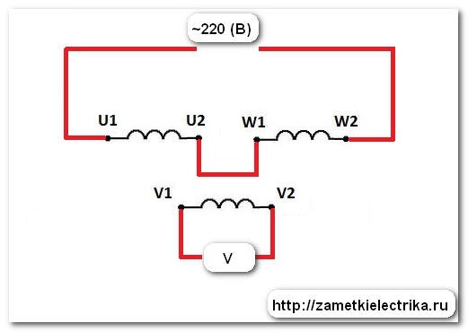
Take the first coil (U1 and U2) and connect it to the second one (V1 and V2) as follows. I remind you that these designations are conditional.
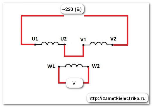
The same scheme in my example.
On the output U1 and V2 we supply AC voltage about 100 (B). You can apply voltage and 220 (V), but I limited myself to 100 (V).
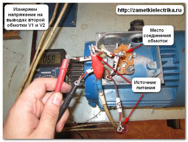
After that, using a voltmeter or multimeter, we measure the AC voltage at the terminals W1 and W2.
If the multimeter shows a certain voltage value, then the first and second windings are connected in coordination. If the voltage at the terminals is equal to zero or has a very small value, then the windings are connected in opposite directions.
Let's see what happened in our case.
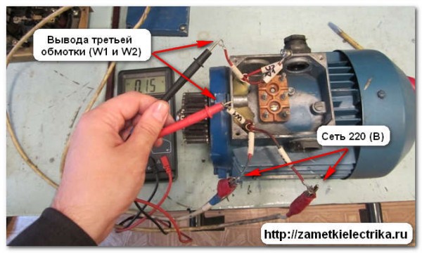
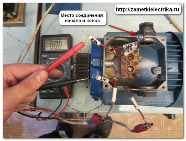
I measure the voltage at the terminals W1 and W2. I get a value of about 0.15 (V). This is a very small value, so I conclude that I connected the windings in the opposite direction. Therefore, on the second winding, I swap the tags V1 and V2 and take the measurement again.
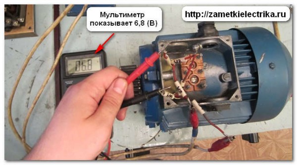
After replacing the terminals W1 and W2, I measured the voltage of the order of 6.8 (V). This is already something like the truth.
I conclude that the first (U1 and U2) and second (V1 and V2) windings are connected in coordination, which means that this marking of their beginnings and ends is correct.
The only thing left is to find the beginning and end of the third winding (W1 and W2). We do everything in the same way, only we connect them according to the diagram below.
It turned out a voltage of 6.8 (V). So the marking of the beginning and end of the third winding is correct.
Step 4
After determining the beginning and end of the windings of a three-phase asynchronous motor, you need to check yourself. To do this, we connect the windings with a star or a triangle, depending on the type of motor and the mains voltage. In our case, I connected the motor windings with a triangle.

I apply a three-phase supply voltage to the windings - the engine is running.
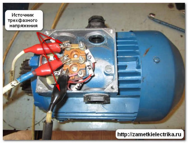
We can conclude that we found the beginnings and ends of the motor windings correctly.
There are several other ways to determine the beginning and end of the motor windings, but I personally use this one.
P. S. If the article was useful to you. then share it with your friends on social networks. And if you have any questions about the material of this article, then ask them in the comments.
238 comments on the entry “Determining the beginning and end of the motor windings”
Hello. I have a question on a slightly different topic. There is a 220 5 kW brush motor, can I make an alternating current generator out of it?
And what is the engine? Three-phase or single-phase…
So you can do it in any case, only there will be no power.
very simple and fast way determining the beginning and end of the winding. Quite often I have to deal with such a problem, thanks for sharing your experience, I'll take note !!!
Well explained - understandable)))). There is a way to use a 9 volt battery when 220 (V) is not available.
zdravstvuyte,ya jivu v baku,ya toje na workote stalkivayus s takoy problemoy,vaw sayt 4asto pomogaet mne)o4en polezniy sayt,spasibo vam
Please. Very glad to hear it.
Yes, the site is really great. Thank you! I will periodically read, gain information.
and if the motor is assembled into a star and the beginning and end on all windings are swapped, the motor will rotate in the opposite direction?
Thanks. cool, i just understand
Respect to the creator of the site, interesting and informative, I accidentally came in and now I can’t tear myself away, a lot of useful information. Question: if in a 3-phase motor one winding is opposite. Why is it dangerous?
The same wiring diagram for 220????
Alexey, I do not quite understand you. What circuit are you asking about - to determine H and K windings?
on the last photo, the connection diagram is a triangle, but connected to 380, it was necessary to connect a star then, maybe I'm confusing something? And if, when determining the beginning and end of the windings, the multimeter shows some voltage, then the beginning of the windings will be the ends on which power is supplied (as in the photo)? Is it possible to use a battery or something else as a source?
Interested in how to properly connect start capacitors to an electric motor. and a worker to operate the motor from 220 (maybe there are any photos?) It is planned to install a 1.5 kW motor on a compressor with a belt drive, so a powerful start is needed.??????
In the last photo, the motor windings are assembled into a triangle, and 220 (V) can be applied to them. Yes, there is a way to determine the beginning and end of the windings using a battery, but this is a topic for a separate article.
I determined the beginnings and ends of the phases, connected a triangle for 220 according to the scheme. After a minute of idling, the motor gets very hot, maybe a winding malfunction or something else?
Is the ohmic resistance of the motor windings the same?
yes the same on all 3 phases.
Alexey, what type of engine are you trying to connect?
Thank you for the interesting and visual presentation of the material)
Good afternoon.
All very helpful thanks.
Tell me what is the reason, I decided to check the windings of the asin of the engine that I inherited from the garage, I found the 1st pair quickly, but the second winding led me to a dead end, two windings reacted to the beginning of the winding showing approximately the same resistance, less than on the first winding .
I think it could be an interturn short circuit. Describe the symptoms of a burnt engine, I think for many this information may be useful. Thank you.
Vyacheslav, the symptoms can be different. For example, there may be a break in one of the sections of the winding, in this case, in one phase, with a “ring”, the multimeter will show a break. There is also often an interturn short circuit in the windings, in which case the resistance in such a winding will be less than in the others. Another option short circuit two windings, in this case, two windings will “ring” at once with each other.
Good afternoon, there is a good way to assemble an open triangle, that is, the windings are assembled in series, we apply a voltage of 220v to the ends of the assembled circuit with a multimeter, we measure the voltage at the ends of the windings on all three windings, the voltage should be the same if not, then we change the ends in places and measure again when the condition is reached, mark from left to right start end, start end
Thanks, I'll try this method.
You wrote that you are changing the tags V1 and V2, probably you are changing the conclusions of V1 and V2 themselves in places?
tell me whether it was possible to find what you were looking for using the proposed method conveniently or not
well said!
if you already have a multimeter, then, after determining the windings and putting on the tags, simply connect the two windings and measure the resistance, in case serial connection the resistance doubles: R1 + R2, or otherwise decreases according to the formula: R1 * R2 / R1 + R2 (it will be visible to the eye that it is really less) .. no need to connect a voltage of 100 - 220 volts, a light bulb through a battery ..
With a multimeter, we measure the resistance of two windings, and we need the winding direction of the motor windings. And these are completely different things - do not confuse.
But what if you still mix up one winding ...? How will the electric motor behave and what will happen if it works like this for 4 hours ...?
thanks for good article and a cool site, quite often I sit on it, although I have a higher Electromechanical education and work as an Electromechanic on a ship.
At the university, they give knowledge, but they still need to be comprehended, now I have access to practice again, I'm starting to learn to understand and comprehend the basics!
The most important thing is that there is an opportunity to go and take and conduct such experiments to consolidate in the head, you need to do it with your hands!
The question is, that is, we supply the supply voltage in the terminal block to the winding rings? with numbers 2 (U2,W2,V2) ??
And we were also taught to put a dot on the winding diagram, this shows its beginning.
The same, but I think it’s not important, we were taught to supply power to the winding which is itself, and to measure voltages on 2 others - well, that one doesn’t matter, because so why does our ED work like a transformer?
Please do not take my writings as a remark! This is just communication, reasoning.
Thanks again for the article!
Another question, I hope the topic is why the location of the windings on the terminal goes obliquely u1-w2; v1-u2; w1-v2.
Is this the wiring diagram?
The thing is, if we just connect U2-U1; V2-V1; W2-W1, then the motor will simply be energized and there will be no torque! So there is no electrical EMF shift of 120 degrees?
Please clarify my theoretical gaps!
Sincerely, Eugene!
The terminals are set so that it is convenient to switch between star and delta. If you connect terminals U2-U1; V2-V1; W2-W1 between themselves and apply a supply voltage to them, then nothing will happen at all, because the same voltage will be applied to each winding, respectively, there will be no current in them. The engine doesn't even twitch.
Please tell me, if you turn on two arbitrary windings in series with each other, turn on the lamp in series with them, and apply voltage to this circuit, then when turned on in the opposite direction, the lamp should not light up, but when it is turned on, should it?
This is a question, not a statement. The course of my reasoning: with a coordinated inclusion, the current will flow through the windings, and with a counter-EMF, induced in the windings will mutually "eat" each other and the current will not flow.
I wonder if I'm right or not? And then I feel that somewhere before the "worm" is in my reasoning, but I can not understand where exactly.
Alexander, in principle, a good idea, but how do you determine the required nominal lamp voltage - 12 (V), 24 (V) or 36 (V)? Isn't it easier with a multimeter?
Hello! ... then, according to your theory, if the windings are not closed in series, then there is no induction ... then the engine will not turn, right? that when one of the three windings is connected to any of the two, the value somehow changes (a little more actively) ... in general, I spat and connected it, as I connected it for the first time, it seems to pull the load .. - now think whether the multimeter is completely Chinese or with an engine something, not that ..., whether I'm a fool or all together)))
P.S. ... and how many degrees -C should the heat-resistor be connected and where should it be effectively located, in relation to the engine?
Koly Palkin, are you asking about thermistors (with a positive temperature coefficient - PTC resistors) that fit into the motor winding or about a thermal relay?
And as for the multimeter, it’s not always at hand. They call and ask to drop in for a minute to help, but I don’t always carry this device with me in my pocket. Therefore, I would like to calculate the “handy” method)))
Dmitry, you still didn’t answer, you tried the method I described above about the open triangle
Good afternoon! There is a three-phase 380v motor, but without a tag. What are the parameters of the motor and in what way can I determine it myself? Thank you.
Alexander.
Then you can take templates for speed calibration, print and stick with tape on the end of the motor shaft, and then turn it on under fluorescent lamp. If the image of the template is visible, then the revolutions matched.
And you don't need any more information.
alexander the speed of a 3-phase conductor can be determined by the number of poles
the three-thousander has 2 of them
so say the rewinders.
Thanks Dmitry, I really liked your article. Although I myself use the method using a battery to find the ends of the windings. And to make sure that the ends are found correctly, I assemble the windings into a star, I connect the tester with probes to a common point and one of the three remaining terminals, and connect the battery to the other two terminals, if the ends are consistent, then the tester for opening the battery does not respond if the windings are assembled on the opposite side, then the arrow instrument is rejected
kivin, the rewinders are of course right, but you mixed up:
3000 has 3 pairs of poles, and 1500 has six pairs of poles, and so on - with a decrease in revolutions, the number of pairs of poles increases.
But the question is, how to see and count them? Yesterday I looked at 3 stators and only in one I managed to see 12 clearly expressed windings. At the same time, I'm not sure if I counted them correctly.
alexander, of course, I meant 2 poles per phase
but this is not the essence, but an occasion to reflect - suddenly it will dawn on someone
by the way about serial connection 2 windings and lamps:
you probably used AC voltage for power supply
Could this be the reason for the failed experiment?
kivin, a worthwhile thought with tension, I'll try tomorrow. Thank you.
Alexander:
12/14/2013 at 00:30
Admin, today I tested my theory with a light bulb in series in practice. The theory does not work. The 220 volt lamp burns brightly with ANY windings turned on. I tried to supply both 220 and 380. By the way, the engine rotates slowly (about 120 rpm) the inclusion of two windings, which is quite surprising ...
Dmitry is right. When the specified circuit is turned on, 3.4 V is induced on each winding; they either add up with a coordinated inclusion - 6.8V, or subtract (extinguish each other). 0.15V is obtained due to differences in winding resistances - hundredths of an ohm. Each engine, if I may say so, has its own coefficient. transformation U1 / U2 and the voltage is not 6.8V, but different. you can use a light bulb, but a multimeter is better. When one of the windings is turned on, oppositely relative to 2, according to those turned on, many motors begin to rotate (at idle), the speed is less than the nominal one. It is necessary to look for an error in the connections. The windings are designated C1-C4, C2-C4, C3-C6. The theory always works.
I'm waiting for Dmitry to calculate compensation currents - over a 6 kV network?
Alexander:
02/06/2014 at 00:20
Alexander.
You can include it in a 3-phase circuit, measure the current in the motor phase with clamps, and from here calculate the power:
The formula for calculating 1.73 (root of three) * I * 380 (W) - we get the power. There is still “cos φ”, but we take it as a unit, so we don’t take it into account in the formula, for an approximate definition it will do ...
I will add:
P \u003d 1.73 x 380 x I x cosf
cosf - 0.9-0.7, take the average value or look at the size of the engine. For powerful engines, cosf is closer to 0.9, for small engines it is closer to 0.7
Alexander, however, nothing will work out for us - this is how we find out the idle power of the engine. And how do we find out its rated power?
Good afternoon, there is a two speed polish motor. There are no tags and pads. So I understand that the ends of the windings are hidden inside. Come out 6 ends. 3 ends of the windings of a star for 3000 revolutions and 3 ends of the windings of the second star for 1200 revolutions. Most likely, the common twists of the stars are hidden inside ... Is it possible to connect such an engine to 220. Thank you
Nikolai, how do you know that the engine is two-speed, even if there are no tags on it. At a minimum, you need to know at least its type in order to accurately answer your question.
very well shown, did everything)) works
The method is fast if the electric motor is 1-speed and if like I have 12 of them
As I see in the pictures, an engine of less than 5 kV with a power, there is an even simpler way to start the same way as you have a continuity of the windings and determine the ends to a certain winding. Then you connect with a star and turn on the voltage if the engine heats up and makes a noise. and makes noise you return to the place of the next one you change places .... a total of 3 attempts are possible, provided that if it fails, the windings will be returned to their place. REPEAT THIS IF THE ELECTRIC MOTOR IS 5 KV
In the camets there was a question how to change the rotations To change the rotation, it will be possible to precisely change the 2nd phase in places
(sorry for ignorance)
Everything is well and accessible explained, but I would like to make a comment.
In the literature and in technology, the designations of the beginning and ends of the windings are designated as follows: C1, C2, C3; C4, C5, C6.C
Sincerely, Vasily.
Thank you, Vasily. But before making reasonable comments, study the new GOSTs. According to GOST 26772-85, new designations for the outputs of the windings of electric motors have been introduced. I wrote about this in an article about.
I accept criticism in my address (according to the designation of the ends of the terminals of the windings of the electric motor), which means I am a little behind ...
Sincerely, Vasily.
Tell me, please, what ohmic resistance should the multimeter show for good windings of a three-phase asynchronous motor with a power of 4 kW? Thank you.
Dmitry, it all depends on the specific type of engine. The measured ohmic resistance of the motor windings should not differ from the factory value by more than 2%. For example, AOL2-32-2, 4 (kW), 220/380 (V), 1.19 (Ohm). Another example, 4A100L4, 4 (kW), 220/380 (V), 3.36 (Ohm).
The thing is that the type of engine is unknown, three wires are brought out, how it is connected inside is unknown, but I think that it is a star. If so, then the resistance measurement gave the result of two windings connected in series. About 3 ohm. After removing the covers on the ends, a rather large amount of moisture and wood dust was found (the engine was running on a circular). The engine suddenly failed - the machine just began to cut down. Is it possible to hope that after drying it will work, if it is known for sure that it did not smoke, does not stink of burning and windings without visible darkening? Sorry for the wordiness, thanks in advance.
Dmitry
Addition. The engine has been running for several years. three-phase network 380 V outdoors (not indoors).
Dmitry
Dmitry, after drying, it may well work. At our work, the pump motors are constantly drowning in water. We disassemble, dry, and as soon as the insulation is restored, we turn it on again.
Thank you very much for your advice.
Dmitry
Tell me, there is an engine (1.5 kW, 380). It was connected to a star, having disassembled it, brought the ends out from one point to connect with a triangle of 220, I measure the resistance of the windings 1st shows 6.0 Ohm, 2nd -0.5 Ohm, 3rd -- 0.6 Ohm. Does such winding resistance mean that the motor is faulty?
The winding resistance must be the same. In your case, the resistance is different, and one winding has much more than the others. This should not be - such an engine cannot be turned on.
Admin Dmitry, I completely agree with you, the engine is faulty. I just can’t imagine what kind of malfunction it is, in which the resistance increases? When it breaks, it is much larger, when it turns, it is less ... Could you explain if you know?
A very useful site, I would like to know the winding data of two high-speed engines. They brought it to me for rewinding, and there the whole circuit practically burned down, only one output end remained. Engine type M132JST. 3.7/2.0kw
A real electrician always helps another electrician. thank you.
Hello! My engine is buzzing, the resistance of C2 with C1 is 1.4 ohm and C2 and C3 are 10 ohm, but relative to C3 on C1 and C2 the resistance is the same, 10 ohm. Does this mean that the ends of the windings are not correctly defined beginning and end? Or something else?
Andrew. This means that your motor has died. Turn circuit of the winding C1.
Good day, I have a compressor for the Carrier air conditioner, we have 6 pins marked 123 and 789, but they only call each other, i.e. 1co2.1s3.2s3 and 7s8.7s9.8s9. On the motor nameplate 380YY. How to connect it correctly? Thanks
I think 7,8,9, close to a star, and to 1,2,3, supply three phases. Or vice versa. If it is very bad to cool, then assemble a triangle from them. my thoughts. We are waiting for specialists.
Oops. I'm wrong! cannot call from 3. Sorry, there is something more serious.
you most likely have a two-speed two-star engine, you can first apply phases to 123 to try one speed
a ground wire to the zero case is not needed, since its resolving zero will appear there at the point of contact of 3 windings
Good afternoon. The problem is this, the generator is synchronous single-phase without brushes. They brought from the repair with cut off phase tags, you need to find the beginning and end
alexey t,a why do you need the beginning and end of the winding in single-phase? It is SINGLE-PHASE ... As I understand it, there are two windings: one power and one capacitor. They can be distinguished by the cross section of the wires. If I am mistaken, correct, we will figure it out together.
all the more interesting we have 3 windings: 2 - 110v each and one capacitor. cond-th is not difficult to find with power is more difficult.
Well, then turn on both power supplies in series, with each other and a light bulb. Apply a change of any value and measure the output with a voltmeter. voltmeter. Then turn over one of the windings and measure again. In which case there will be more, that is the agreed inclusion.
but I don’t understand why there are 2 power windings. but these are already trifles.
My personal opinion, I can be wrong, I have never seen such a generator. If you still want to do such an experiment, please unsubscribe, I'm wondering if this method works.
Those. Measure on a capacitor winding?
It is possible on it, but I meant on a light bulb. But you are right, it will be even better on a capacitor.
A question. How long can voltage be applied to two windings in series? (220 volts, to determine the voltage on 3 windings)
Only 15 minutes on your site, and I learned so much!) Thanks for the article, I will wait for new ones!
10/28/2014 at 18:04
"A question. How long can voltage be applied to two windings in series? (220 volts, to determine the voltage on 3 windings) "
At least how much.
If Un -380, and new motors are tested for 1.3 Un (495V) 1 min or less depends on the ratio of In and I at 495V.
Therefore, 220V motor windings "withstand" at least 24 hours with any connection.
To look at the tester (or light bulb) oncoming or consonant connection of 2 windings, 2-3 seconds are enough.
We apply an alternating voltage of the order of 100 (V) to the output U1 and V2. You can apply voltage and 220 (V) - we supply line voltage? or from phase and zero?
It is safer to apply a phase voltage of 220V if the motor has Un - 220 or 380V
I have such a question that the ohmic resistance to direct current of the electric motor exceeded instead of 2%, it turned out to be 9.9%, what is the problem? This is a coil circuit, the test of 13 kV of a change, all three windings withstood, and both insulation and absorption leave much to be desired to abs = 2.08, the motor after a complete rewind
Diaz, if the engine is after rewinding, then most likely this is not an inter-turn short circuit, but a winder error, which may not have wound the winding sections correctly or took slightly different wire sections. So it turned out that you have different ohmic resistance in different phases. With such a difference of 9.9%, it is forbidden to turn on the engine.
This is why it is necessary to measure the ohmic resistance of DC windings, because during a high-voltage test, a conclusion is made about the insulation of the windings relative to the motor housing, and absorption shows the moisture content of the insulation.
Good day, please tell me how to connect a pointer ammeter to a 4kw electric motor from 220v (homemade DC)
Sergey Alekseevich, if the ammeter is direct-on, then take the ammeter with a limit of up to 25-35 (A) - this will be enough. The ammeter is connected in series, i.e. into a gap, for example, a phase wire.
If the ammeter is a transformer inclusion, then they all go to the secondary current 5 (A), the difference will be only the limits on the scale of the device. Such an ammeter is connected to the secondary outputs of the current transformer.
Good day!
I came across a two-speed engine manufactured in 1968 by AO 31-4-2T at 380v.
6 wires marked 2s1, 2s2, 2s3, 4s1, 4s2, 4s3 are brought into the box. Is it possible to connect it to single-phase network 220v.
P.S. the tag shows the stator winding connected in a triangle with vertices 4c1, 4c2, 4c3.
4c2
/ \
2s3 2s2
/ \
4s1- 2s1- 4s3
and the possibility of connecting a triangle and YY is indicated
Tell me how to properly connect a two-speed electric motor, the speed ratio is 1 to 2, that is, 750 and 1500 rpm. min. Six outputs on which there are no tags, only wires are connected in two groups of three. Does it matter which group to connect to a triangle, and the second to a double star, if it does, then tell me how to determine these groups, which is connected to a triangle, and the second to a double star
Anatoly, I need photos of the tag and the boron engine. Email them to me and I'll take a look.
Thank you Admin, using a practical poke method, when connecting the voltage, it seems to have figured out, it turned out according to the Dahlander scheme with a constant moment, that is, a triangle and a double star, everything works fine
Maybe my question is a little childish))) but still. As I understand it, the beginning and end are conditional in the engine, that is, one of the two ends of one winding can be taken as the beginning (even if it was originally the end), and from it already dance, the main thing is that a consistent current flows through the windings?
Alexander:
03/18/2015 at 12:50
Yes, absolutely conditional.
Good day, please tell me a single-phase motor with a working capacitor of 50 microns, if you look at the engine from the side of the pulley, then spin to the right side with good power, it starts the milling machine with a belt in the load, though with an 80 microns conder, 4 wires come out of the engine, two yellow blue and black blue and the yellow one hangs on the condeconder and the black one and the yellow one for the network I change the black one for the conder blue for the network it turns the other side but there is no power without a belt, it starts up, I start to tighten the belt, the engine goes out, tell me how to figure out how to connect it so that the engine with Chinese turns to the left side with normal power high pressure washers some kind of aquarace or something like that on the body of the sink it says 2500 watts
Vladimir:
03/20/2015 at 22:50
Could you add commas? And then you "execute cannot be pardoned" turns out. I am from Ukraine, I welcome people who do not know Russian. But the rules for placing commas in these languages are the same.
If I understand the question, I will try to answer, but so far I have not succeeded.
Although we have ealex special in such riddles. Maybe he'll figure it out.
If I suddenly understood correctly, turn off everything and give us data on the windings. It seems that there should be two, absolutely independent.
And something else, the capacitor you have is too large for a single-phase motor. Although again, we do not know the power.
Good day. please tell me a single-phase motor with a working capacitor of 50 microns, if you look at the engine from the side of the pulley, then spinning to the right with good power starts a milling machine with a belt in the load, though with an 80 microns conder. 4 wires come out of the engine, two yellows blue and black, blue and yellow hangs on the condeconder, and black and yellow on the network, I change black to conder blue to the network turns the other side but there is no power, without a belt it starts up, I start to pull the belt the engine goes out. tell me how to figure out how to connect so that it turns to the left side with normal power. the engine is from a Chinese high-pressure washer (some kind of aquarace or something like that) 2500 watts is written on the body of the sink, there are no tags on the engine, but on the body of the sink itself on the tag 2500 watts, there was such a conder 50 microns. I climbed on your site like I found a shot, you mention about the connection in the engine, I guess that I also probably connected everything inside and brought everything out ready for the right direction of rotation. sorry for the comma and so on, I write on android so I barely get the letters, I rarely use the sensor, but there is no Internet on the laptop, they stole the cable on the 400 m line
If the working capacitors (capacity 10 + 10 + 50 = 70 uF) were selected according to the simplified formula (C = 66 * Pnom), then it turns out that the power of your engine is 1.1 (kW), although it may be 0.75 (kW), and 1.5 (kW). In general, if there is no tag on the engine, then the engine power is determined by its overall dimensions, according to the reference book.
the admin wanted to ask, in the article you assembled it into a triangle and applied 3 phases, that is, did you make the voltage phase 220 and linear in the region of 100V?
Are you on this 220 V. Wiring one phase one zero? Or how ... And there is also a cross-section of the wiring?
If you already have a multimeter, then, after determining the windings and putting on the tags, simply connect the two windings and measure the resistance, in the case of a series connection, the resistance doubles: R1 + R2, or otherwise decreases according to the formula: R1 * R2 / R1 + R2 it can be seen that it is really less) .. no need to connect a voltage of 100 - 220 volts, a light bulb through a battery. Next answer With a multimeter, we measure the resistance of two windings, and we need the winding direction of the motor windings. And these are completely different things - do not confuse. Answer We measure the resistance of two windings AS SERIES OR PARALLEL?
Hello. I need advice on how to find the beginning and end of the windings. There is an electric motor, after rewinding. Two speed. 9 outputs in a terminal box. How to find the beginning and end of the first speed and the second?
Michael:
06/09/2015 at 13:22
It may very well be that you don’t need to look for anything - there are already two windings connected in series 3 phases + 3 phases with a lead between them. Two star engine. The middle terminals are connected to a star for one speed, and the extreme ones are connected to a star for another speed. I have these on the cooling tower - 30 / 7.5 kW.
Thanks for the answer. The problem is how to determine which pin refers to which speed and where the start and end are. Two-speed motor, one speed is twice the other. It is connected through three contactors. One triple to the contactor to the network, the other triples of conclusions, each to its own contactor and briefly between them. For spin-up, the power contactor is closed and one of them is short-circuited, as the motor is untwisted, the other contactor is switched on shortly. Motor 200 kW. After rewinding, 9 pins stick out and that's it.
Michael:
06/09/2015 at 23:50
In principle, everything converges with my version. The fact that "shortly" - this is the star. But two stars are used for continuous operation at any of the speeds. But that's the little things.
In fact, you need to find three branches with maximum ohmic resistance. These will be the desired (as in my circuit) windings.
Next, you need to exclude “average” conclusions from the search. Elimination method - in each found branch there will be a conditional beginning and a conditional end. The output that rings with the beginning and end of one branch will be the middle output that we do not need.
After such manipulations, we "get" a conventional motor with six leads.
And then, to find the real beginnings and ends, we act as described by the author of the topic.
Next, we determine the speeds (here we need the middle output that we “discarded” at the beginning) - the part of the winding responsible for the low speed will have a higher ohmic resistance than the part that is high-speed. multimeter will not help you. Measure only with a bridge.
Please do not take these arguments as an axiom, take them as a direction for reflection. I am not an experienced electrician - I describe my actions when manipulating my engines specifically, but they are German.
Hello. Tell me what to do. I was going to connect the motor. into a triangle (I saw how to do it on YouTube, it was shown there using the example of three windings), I dismantled all the twists there turned out to be 12 ends. I don’t know what to do now, I won’t even do it how it was. It needs to run on 220V. Motor 380V, 1410 rpm, Y, 2.2 kW. There were three outputs on the terminal block. Thank you.
... name, sister, name! ... Does the motor have a full name?
diman, you obviously have a nameplate on the motor. Give us everything that is written on the nameplate.
4AMX90L4U3 is this what?
Diman, yes, this one. The rest you mentioned in your last post.
But I am a pass. I can’t understand where you managed to find 12 ends, but I believe that this is so.
maybe someone else can help you...
On the net regarding this type of motors there are words about built-in temperature sensors, maybe there is one here? In general, climbing into such things with the help of all sorts of Tyrnetov's advisers ... And even if your hands itched, what was it worth taking a marker and a sheet of paper?
surfactant,
There are no sensors there. An ordinary old four-pole motor under a star, about 85 years old. A person most likely climbed into the windings, and there, if there are side cutters in his hands, you can find 112 ends.
the diman must first be restored as it was. disassemble the electric motor so that the ends of the stator windings can be seen
and look carefully. each motor winding is shifted
in relation to another with the same step
the engine is without a nameplate, it’s old, it’s quite difficult to understand its type, because it’s not a specialist. There are 6 conclusions. There was a triangle connection.. I disassembled the connection, it was twisted. I tried it and it gets warm, even the smoke went, the smell .. what could be the reason ..
There is only one reason, if you are 146% sure that it is in good condition, to the point that the windings are turned on incorrectly. You have to get used to doing everything new and unknown with marking conclusions and drawing, and better - photo, each step, then it is much easier to understand the incomprehensible, and now there is only one way out - to look for an experienced and competent electrician.
Sasha:
07/26/2015 at 22:55
Once you saw the smoke, then you no longer need to find out the reasons. Into the trash.
At our enterprise, from rewinding, motors come with a certain beginning and end of windings and even included in a star or triangle, which is quite natural. But there are times when, for some reason, the ends stick out unsigned. To connect the engine in this situation, I always use the following method. After determining the coils, I turn the ends into desired scheme(star or triangle), then I connect it to the network and start the engine. When connected correctly, the motor runs smoothly, but if the ends of the windings do not match, the motor will hum. Then I take any winding and change its ends in places. If the situation does not change and the engine hums terribly, I put the ends of this winding in place. I perform the same operation with the next winding. And so on, until the engine runs correctly. Everything about everything takes a maximum of twenty minutes. The method is acceptable for engines of any power. Does not bring any harm to equipment and personnel (subject to safety precautions). This method can be used both in laboratory conditions and at the place of installation of the electric motor.
Vitaly
genius method. Did you develop it yourself?
No, not by myself. What about problems?
Vitaly:
not that problems, but a strong discomfort from such a method. We have a hydraulic fitter. If the machine breaks down, he doesn’t think either, probably your friend))). He stupidly begins to change everything in a row. And in the end, the machine starts working. We laugh at him, but his method, like yours, is trouble-free)). if you suffer for a long time, something will work out))
There is an old book on the repair of electric / motors, three beautiful classical methods for determining the windings are described there, I can throw it off to the admin for general disgust.
surfactant:
Can i? If you fill in somewhere, or at least give a name for the search engine, I will be grateful.
Alexander:
In my method, everything does not change in a row - only the location of the ends of the windings changes. I personally have been using this method for more than twenty years - no problems, discomfort, etc. At least not worse than sticking an untested engine into the network and observing the smell and smoke from it (see comments above).
Alexander, I'll try to scan the pages somewhere, then we'll decide. So far I can only take a photo, but the quality is unlikely to be at the level. And I can’t give links, because. snatched from a neighbor - she melted the stove in the country, no name, no exit. No data. The book was on the repair of email. motors and rewind to other wires and voltages. There are winding data for some types of motors A, AO, 4A, please ask. Now such data is difficult to find.
Vitaly:
I criticized in vain. I thought about it - disconnecting the windings according to your method is probably even faster and more convenient than using the method described on the topic. And less "smut" with appliances.
surfactant:
Then do not strain with scanning - I am purely for curiosity. Old books are very intelligible and simply explain everything.
Vitaly suggested a simple and effective way. I will try and apply it in my practice.
Admin:
Dmitry, sometimes it becomes necessary to determine the number of engine revolutions with a lost nameplate. Would you like to create a topic about this? I don't know your location, the link is not available outside of Ukraine. If anything, the title of the topic (for the search engine) is "Disks for determining the speed of rotation of an induction motor."
Alexandru, Admin:
Thanks for the feedback!
The problem with determining the speed of rotation of the motor shaft is really relevant. I will also look forward to articles on this topic.
In one of the comments on the site, I already said that we still use the tachometer of the “Soviet era” TCh10-R, although modern digital tachometers are also on sale on the market. Also, the engine rotation speed can be determined in other ways without special devices, for example, using the disks that Alexander mentioned, or by the stator winding, or ... general ways there is. I will write about it in my free time.
Vitaly, do you need to determine the speed under load, or at idle? If on XX, then there are few options 750 (rarely), 1500 and 3000.
If there is no normal tachometer, and often necessary, I would adapt an automobile speed sensor with a Hall sensor and a tester frequency counter, there are many Chinese ones. DS is available at 4.6, 10 imp. per turnover, import and other values. The only thing is to power it from any unit, even a charger with a voltage of 5 ... 12 volts.
SAW, thanks for the advice on the car sensor. I'll try. The need to measure the speed arises in different cases: At idle, for example, when selecting an engine, if there is no tag (nameplate) on it. I have a tachometer, the same one mentioned by the Admin, but he (the tachometer) has recently become "moping" (which is why he supported Alexander's question about other ways to measure speed). It is not always possible to disassemble the engine to look at the stator. But here you noticed correctly: there are few options - you can determine by eye when connecting to the network. A much bigger problem is under load. Here on the "eye" will not work.
Admin, what's with the disks? If possible in more detail.
Thank you!
There is another way - on some washing machines there is a tachogenerator on the shaft - a post generator. current with a fairly linear characteristic, a simple voltage meter is already enough for him, and it is not difficult to obtain a characteristic in volts per revolution - on the same well-known motor in XX mode.
Thanks again, PAV! I will definitely try this method as soon as I get to washing machine:)
You just look carefully, there may be alternating current.
Vitaly:
I gave a link, but the admin removed it for some reason, his right.
Either wait for his topic, or, if urgent, type in Google "Disks for determining the speed of rotation of an asynchronous motor" and the first result will be shown on my page in the EX.UA file hosting.
There, the meaning is primitive - print a disk template on a printer, tape it to the end of the engine shaft, and turn on the engine. It is only important to illuminate the end of the shaft with a fluorescent lamp. If the rotations indicated in the template match the actual rotations, you will see a pattern on the rotating template. If they don't match, you won't see anything. Stroboscopic effect, as when shooting a helicopter propeller on TV - the helicopter flies, but the propeller does not move.
PAVu: Thank you!
Alexandru: I went to your page, downloaded and printed some CDs. I'll experiment just in case. Thank you!
Hello. And what are the most practical ways to determine the beginning and end of the motor windings?
Hello dear and seasoned to us boobies Admin! (deflection counted)))))
I am very interested in a question that does not give me peace of mind. There is an engine, approximately 2.2 sq. The tag is missing. I have been tormenting him for several days, with the connection. Why, when connected with a star and starting from a 100 microfarad conduit, it works fine, quietly, and absolutely does not heat up. But how do I connect it with a triangle (if I don’t confuse it with wires) with the same launch from a 100 microfarad conduit, does it HEAT in 5-10 minutes? Of course, I immediately remove this conder from the circuit, that is, only for launch. I need the engine itself like emery. The load will be minimal. So why connect with a triangle if it works quietly from a star?
Denis:
very valid question! there really is no need to connect a triangle. work on a star. Engines are initially made under a star or a delta. don't mess with the tech.
Oh stop it! If INITIALLY, then there would be either THREE or FOUR wires / outputs !!! And so, six, and here options are possible. The difference between a star and a triangle must be both known and understood, then you can write about your understanding.
In this case, there are two options for switching on, the current and torque are different. With such defective / defective circuits, the capacitor first of all determines the direction of rotation of the rotor, then the rest. There will be no capacitor - the rotor has one fig where to turn.
surfactant:
(c) Oh, stop it! If INITIALLY, then there would be either THREE or FOUR wires / outputs !!! And that's six."
You are wrong (IMHO). Sometimes the engine starts on a star, but works on a triangle. If you stupidly attach it to a star, it will warm up.
This is far from everyone, but only a powerful engine, or a loaded one, and it starts on the contrary - a triangle and then, with the rotor spinning through several. seconds - transition to a star. However, it will not heat up, this is a normal operating mode, long.
But you talked about the ORIGINAL, and you continue about something completely different.
Not vice versa, but exactly as I wrote - the start is on a star. Here I am sure, because almost every day I am poking around in their launchers. By the way, you involuntarily reminded me that it is necessary to create a topic on the forum for disassembling the DILM-40 starter. And then the pictures on the mobile have been lying for a long time, but I forget everything.
So, sometimes the nameplate of the engine indicates: star-660 Volts, triangle-380 volts. And if you include it in a star, but apply 380, then it will warm up. Checked multiple times.
Sometimes six-ended motors come from the factory assembled in a triangle. We foolishly first switched them to a star, and they warmed up. In this case, I'm talking about low-power -1.5kW.
In this case, if we are talking about the question of Denis, and not in general, there are no launch switches. Only under a specific voltage, and most often not 660 volts. There's probably 220/380 and nothing more. Both the capacitance of the capacitor / moat and the power on the shaft will depend on the choice of the switching circuit. For a grindstone, a pseudo-star is also quite tolerable, but the start will be sluggish with a massive stone, so a triangle is better.
Hello! I would like to ask a couple of questions about my motors, I hope you can help.
1. Yes three-phase motor. On the nameplate: AOM 11-2, 3ph, 380 V, star, 0.35 kW, 2700 rpm, 1A, 50 Hz. In fact in terminal box 6 wires (were not connected in any way), rang, found all pairs, all 24.9 ohms. The last winding closes to the case and gives 25 ohms (W1 and case), and 0.1 ohm (W2 and case). Haven't taken the engine apart yet.
Question: I am going to run this engine at 220 V, and sell this engine in the future, which is more expedient: rewind the third winding or sell it to the same buyers as is?
2. Yes single phase motor. There is no nameplate (it was, but I tore it off, it was no longer possible to read anything there). In general, 4 wires stick out - 2 with thick insulation and 2 with thin ones. With thick insulation it gives out 2 ohms (starting), with thin insulation 22 ohms (working).
Question: if you mix up the conditional beginnings and ends of the working and starting windings, there will be nothing terrible, the rotor will simply rotate in the other direction? Will there be problems with the fields, like with a wrong connection in a three-phase motor?
After starting such an engine according to the scheme with a working capacitor on the starting winding, is the circuit with this capacitor and the winding itself completely disconnected, or is only the capacitor disconnected?
There are 5 capacitors MBGCH 250 V, 10 uF, will they go to start such an engine or not? If not, is it possible to assemble a higher voltage battery from them and how exactly, or is it better to buy one for 450 V and about 50 microfarads?
I don’t know the type of engine itself, maybe it will work fine and without capacitors, but still I would like to know.
Thanks in advance!
Yes, in the previous message I mixed up the starting and working windings, with a thick section of 2 Ohm - working, with a thin 22 Ohm - starting.
For the first engine:
Rather, it makes sense to open the covers and view the terminal wires up to the windings. Judging by the resistance, the winding sat on the case at the very end, most likely the insulation was wiped off directly on the outgoing wire.
For the second engine:
a) if you confuse the ends, only reverse will occur, everything is in order.
b) according to the scheme with a working capacitor, the auxiliary winding is constantly connected through the capacitor. It doesn't need to be turned off.
Here is the topic
c) From 4 capacitors MBGCH-250 V at 10 microfarads, you can assemble a battery of 20 microfarads at 500v. The fifth capacitor is out of place. Therefore, if you need exactly 50 microfarads, then just buy. I just don't know how much capacity is needed for this engine. By the active resistance of the windings, this cannot be determined.
We need a selection by typing in the direction of increasing the capacity.
Vyacheslav, on a post dated 03/11/2016 at 04.27- If desired, such a motor can be started at 220, making one winding working, another through a capacitor to obtain the required direction. It’s just not possible to load much, so it’s a grindstone ...
Alexander:
03/11/2016 at 12:13
Thank you very much for the prompt reply. Even if the insulation is worn out - at least it can be wrapped with electrical tape, it won’t melt, what do you think?
Or smear it with silicone? Or which is better?
And how do you connect the capacitors? One pair in series, the second pair in series, and then these two pairs are parallel to each other?
With parallel, it is clear that the capacitance is summed up, the voltage does not change, but what about in series? The capacitance does not change, but the voltage does not seem to grow, or is it somehow wrong?
Vyacheslav:
03/12/2016 at 23:10
1. Must not melt. But suddenly something happens black rag tape, or put preshpan, or varnished cloth, or asbestos. At worst, hammer a wooden wedge.
2. Yes, that's how you connect.
And according to the final value of capacitors, I advised you garbage last time
The formula for calculating the capacity of two series capacitors is C= C1*C2 / C1+C2, i.e. 10*10=100 . Further under the fraction 10+10=20. We divide 100/20 \u003d 5 microfarads.
We have two batteries of two series capacitors with a total capacity of 5 microfarads with a voltage of 500V
Next, we connect these batteries in parallel and get 10 microfarads per 500V.
10 microfarads at 500 volts
Alexander, thanks!
Perhaps it’s better to buy a couple of capacitors of a higher voltage and high capacitance, otherwise if I need somewhere around 30-50 microfarads in total, then I will have to collect a lot of such batteries ...
I can’t even imagine how many of them will be needed there, I turned on this single-phase today directly without conduits, the lights almost went out, the engine made a few turns and then the wire from the power button to the motor burned out, I had to stop.
And I dismantled the three-phase, everything seems to be normal there, the turns are intact, there is nothing to shorten the body ...
Vyacheslav,
You need to look not at the turns themselves, but at the twist where the turns connect to the lead wire. On this twist, the cambric is dressed.
This “voltage” is not needed there, 400 ... 450 V is enough, some work with a working 350 V. but the capacity is needed calculated or close.
surfactant,
yes, 400V is quite enough, but 350 is already risky. The motor is still an inductance with a sufficiently large number of turns. When disconnected, there is a risk of breakdown by reverse voltage, it is much higher than the working one.
It all depends on the material of the dielectric in the capacitor. There are industrial devices where the shift capacitor has 315 volts, and nothing. If we take the Soviet ones, there are types that allow 20% excess of the rated voltage at 50 Hz, and there are 100%, it all depends on the specific type.
For example, there is such a thing: 100uF 250VAC (DUCATI 4.12.80.3.410)
Brand: DUCATI
Starting film capacitor for motors 100uF; 250V; ±10%
I think it all depends on the voltage. If the capacitor is 200 volts, but can tolerate 100% - that is, 400 volts, then why did they write the number 200 on it? I don't see the logic.
The material is a good thing, BUT this is how it determines the amount of voltage that will be written on board the capacitor.
10-20% spread is normal, and then it concerns the capacitance, not the breakdown voltage.
“There are industrial devices where the shift capacitor has 315 volts, and nothing”
I have not met, but I believe that they are. However, I am sure they do not stand in serious inductances.
For example, I (at work) had only 200 volt conduits in the induction furnace, with an operating voltage of 130 volts. The current there was in kiloamperes.
But in the furnace there are only 20 turns of the winding, and there will be no reverse breakdown voltage. And try to put a conduit with such a primitive margin, for example, on a compensator for DRL lamps. Shoot for sure.
Engine DPT-P-22-4, 380V., 0.55/0.37 kW., 3000/1500 rpm YY/Triangle
6 pins, box broken. I assume that all 6 windings are in a ring. How to check? I want to connect to a chastotnik with a power of 0.55. Which scheme is better to choose for the best torque at low speeds, I want to overclock to 4000 rpm. Are there frequency limits?
Thanks for your work.
People, how to check the winding for penetration into the body?
I have a three-phase AOM 11-2, one of the windings called to the case, dismantled the motor - it seems like everything is whole, nothing rings on the stator case with a multimeter. I stick indicator screwdriver into the wire and start to drive my fingers outside the wiring to search for penetration - it doesn’t work, the screwdriver is constantly glowing with a dim light. How to check where the insulation is damaged?
A place where, you are unlikely to find, you can only have a breakdown. This is done not with a multimeter, but with a megohmmeter, or a 220/25 watt lamp and two wires to it. Observing TB !!! - the motor is on an insulated table, etc., gloves - at least the neutral of the network - on the motor housing, then in turn touch the terminals of the windings with a lamp, the second wire of which is connected to the phase wire of the network. The lamp does not light / shine - there is no breakdown, it burns / shines - there is. And detailing is tricky.
Vyacheslav,
If after disassembly nothing rings, then you need to collect and call in stages. When installing which part, it will again begin to give the body - that part to the winding and leans.
And there are already two details - two shields and it is difficult not to notice the place where the winding touches.
surfactant:
Already three, you forgot about boron))
And also track each turn? Clearly, to search means to search everywhere.
Hello, please explain what an additional contact block is and how to connect it to the starter
It is difficult to answer unequivocally, perhaps this means the possibility of increasing the contact groups in the contactors. NOT for everyone, but there is one - just another add-on is installed on top. Give me an e-mail, I'll show you if we are talking about the same thing.
It is also possible to include in series with the working contacts and thermal protection.
Create the material you profile in electronics, the usual additional contact block PKI-22NO 2NZ, please, it’s clear that it is intended for multiplying contacts, so here’s where to connect it to the starter, there, for example, take an intermediate relay, the relay has a coil when it is energized, it closes and opens its contacts, but this additional contact block does not have a coil, how to connect a photo in a comment, please post it!
If you have related questions, then ask them in the comments to that article. Thank you.
such a question - if, when connected by a star, the voltage is connected not to three beginnings, but to three ends (respectively, three beginnings in a bunch) ... will something change in the operation of the engine?
Good day. There is an engine, the tag says that it is 220, three-phase. Only three ends come out. I would like to connect it to one phase. In this regard, I wondered what scheme it is connected to, a star or a triangle. Is there any way to determine this? There are no corresponding markings on the tag. The engine is from a deep vibrator IV ... I don’t remember how it goes on.
Can a star be connected to a single-phase network?
What else, besides "it says that 220" is written, are there any icons?
Maybe a star, depending on what. If it’s for a grinder, it’s fine, if something powerful, it’s unlikely, it’s hard to say without knowing the power.
There are no icons, it says 220v 3 50 ~ Hz. The rest is all the power, year, model of the device, etc. There are no inscriptions anywhere else, neither on the cover nor under it ... in general, nowhere. I'll look at the exact model, I'll write. I just don't know if it's a star or a triangle. I know how to connect a triangle to one phase. I found a schematic on this site, it seems like a star is also connected. I just have doubts, I've never heard of such a thing. I myself am not professionally connected with this, so there is almost no experience with electric motors.
Yes, it doesn’t matter, one phase can be used for one exchange. and two turn on, the rest through the capacitor. The rotor will spin, only the moment on the shaft is different.
Try to measure the resistance.
The engine itself is a kilowatt, only the vibrator will turn, the load is not large.
Igor, most likely your motor windings are assembled with a star for a voltage of 220 (V), i.e. 127 (B) is applied to each motor winding when connected by a star. I have a similar engine (AOL 22-4) discussed in articles about: and connection.
Hello, tell me pzhl. When a voltage of 380 is applied to the second ends of the engine windings, how much will be at the first ends, is it possible to burn the controller if these ends were mistakenly connected to a 24 volt controller?
There are no jumpers in boron, the role of jumpers is performed by contactors, star-delta circuit
hello everyone, I have a question, I connected a motor on which nothing is really written, 400V + 10% and there is no star, no triangle, there are 6 ends, I found windings 1,2,3, started looking, I connected the beginning of the ends through a lamp to one of windings, 4 wires left, 2 connected measured - 0, then changed the wires, measured, 2.2V, changed - 0, set so when it was 2.2V more high voltage in a difference from zero, it turns out that I found the beginning and end (let's say) of the first and second windings, how can I understand which of those two wires will be the beginning and ends of those that I found by measuring, for example. (it turns out NOT THAT which was originally called when measuring resistance?) help a novice electrician)))
If you found three windings, equal in resistance, independent, why should you look for something else? Turn them on either with a triangle or a star and apply voltage. The rotor must rotate in any direction. If this direction does not suit you, turn over the leads of one winding and get reverse rotation.
in the end, when I figured it out, the engine was already closed, but still my question remains, how to understand where the beginning is and where the end is. I measure u--u1+c1--c. I measure, I get u and c as a result I get a higher eg, and then what will be the beginning and end for c and u?
SAW, that is, it turns out when I find the windings by measuring the resistance, will it be the beginning and end? called 3 windings of 25 ohms connected them into a star and applied 3 phases and everything?))
then why is this whole topic with a voltage of 100 volts, or as I did through a lamp so as not to apply 220 to the winding
Ilya, where else is more detailed ?! If you have a three-phase motor and there are 6 ends in the terminal block, then proceed sequentially, according to this article. You found three different windings, they have the same resistance and that's good. And then you write that you apply voltage to one winding. Why for one?! Take a closer look at the diagram in the article - we apply voltage to both windings by connecting them in series. And we measure the voltage already on the third winding, and so on.
that's it, I figured it out, I'm sorry for my carelessness, I connected a 3-phase fan, thank you! scheme works)
Alexander:
08/11/2016 at 20:37
there is a single-phase motor with windings of 1.6 ohms and 6.7 ohms, without a capacitor (working and starting). Suggest a reverse scheme with a block of buttons “Stop”, Back”, Forward”
Alexander, I propose to read a bunch of material in the topic "reverse single-phase motor"
Please tell me how to properly connect an inductive motor for 3 phases cos 0.08, 90 kilowatts
How to understand "inductive" and cos 0.08 ??? There is no such cosine.
To what network?
The method is good for motors with the same winding resistance, but motors for home fans have 4 pairs and different winding resistances, the battery method (intermittent connection) will probably be better here and follow where the instrument arrow deviates (digital will not work).
And why in such an engine to determine the polarity of the windings?
Hello! I have this question. I gave a 3-phase asynchronous motor 3000 rpm to rewind. 0.79 kW. Asked to connect with a triangle. After rewinding, 6 ends are brought out and twisted in pairs. means the beginning and end of each winding are twisted together. Run like this or look for the beginning and end of each winding? How will it work if left as is? Please clarify as I am not an electrician.
Why did you decide that way - ... it means the beginning and end of each winding are twisted together ... (c) Check first, make sure.
Hello! there is an asynchronous motor 2.2 kW, it is in the gearbox for drilling. The resistance of all windings to direct current is 2.8 ohms. The resistance between the windings relative to each other and the housing was measured with a megohmmeter at 500 V. Norm. Problem: At idle, the engine runs, turns. Under load, it does not develop the required power. First connected via frequency converter for 220 V, delta connection, does not drill. then, for the experiment, they connected a star to 380V, the same picture, it dies under load, although there are no comments at idle. The gearbox itself is in perfect condition. Tell me what to do? could the problem be with the rotor? it is unlikely that all three windings could burn equally to 2.8 ohms. And in general, what orders should there be resistance? thanks in advance!
Hello! I'm an electrician, but this is the first time I've seen this. The engine came from a rewind, 380 V, when it gave it away, there were three outputs in the borne, and it came from the 9th. The first pair with a tag is the second 2 ° 5, the third 3 ° 6, and plus three more wires without a name, question! How to understand it? What to twist with what and where to apply voltage
Are you kidding??? Isn't it easier to ask the winder?
hello, tell me, the engine looks similar to the AOP 22-4 (aluminum corps from the frame)
THERE IS NOTHING else. WINDINGS MEASURED: 1-35.6 ohm; 2-38 ohm; 3-35 ohm. Based on all the explanations on the site, I understand (maybe NOT CORRECT) that the resistance of one winding
differs from others by approx. 7-8 percent (instead of 2) and is it still NOT big
resistance? question: what could be the reasons (such a difference and such resistance) and is it possible to do something or throw it away7! Thank you. And the site is from-
personal, BIG THANKS TO ADMIN and others for their patience and explanations!
Good health to everyone! I want to apologize for the wrong information about the existing engine (from 09/17/2016 to 21.08).
L-250; d-14; h-90 and there is NO box (ONLY CONCLUSIONS), OUTER DIAMETER-150; BED DIMENSIONS (Twisted) -165 by 150. Question: what kind of movement? And about the resistance windings:
35.6; 38; 35th
Sorry. Thank you.
Hello! The method mentioned in the article does not work for me! For the sake of experiment, I decided to try this method on an engine with marked beginnings and ends of the windings. The first motor is 0.25kw/380v. I did everything as indicated in the diagram in the article - first I connected v1 to u2 (according to the article, on the opposite side), applied 220V to v2 and u1, measuring the voltage on w1-w2 showed 16.5V (?!). Next, v2 connected to u2 (consistently) and applied 220V to v1-u1 - the measurement on w1-w2 showed 0.6V (?!). That is, the results were exactly the opposite. At the same time, the engine hummed like a tractor.
The second motor is 1.3kw/380V. Connected in the same way as on the first engine. Both with the opposite and with the coordinated connection of the windings, the measurement results gave a voltage close to zero. Can you explain where the dog is buried?
Good day! The article is very helpful and clearly explains everything. Thanks to the AUTHOR! Does anyone know how to do homemade device to determine the beginning and end of the windings. To do without a mileAmp Volohmmeter. I want to make for an enterprise. The problem with the definition of windings appears quite often. I want everything to be simple and understandable even to a non-specialist. Thanks to all.
Alexander, look again at the connection diagram of the beginning and end of the windings in the article! In your first case, you just connected the end of U2 in a consistent manner, connected it to the beginning of V1 and applied voltage to the beginning of U1 and the end of V2 (as in the diagram). And in the second case, the magnetic flux of the windings is directed towards each other, and the result on the multimeter is obvious. But with the second engine is not clear. Look again at the beginning and end of the windings.
I have been using this method for a long time, it is very simple. Thanks for the article, it was interesting to read. I really like how the author thoroughly explains everything, we were not taught TOE at the institute like the author in his articles)
Hello.
The method described in the article is applicable for finding the beginning / end of high power EM windings, for example, 250 kW? Thank you.
Valentine, this method is applicable to engines of absolutely all capacities.
Hello.
Very good site, lots of useful information.
While waiting for an answer, I managed to test the theory with practice. I did not manage to use this method on a 250 kW engine. Low winding resistance leads to short circuit. I used the “reverse” method, we supply 12 (or so) Volts to one of the windings, we measure the voltage on the other two, if the windings are connected in a consistent manner, then the voltmeter will show something (several Volts).
In the first figure, the phase U1-U2 is the end numbered correctly? And in the V1-V2 phase, they simply changed the tags and now connected the end of U2 to the end of V2 (which was more precisely V2) got confused ...
And so that there is no short one, can you still turn on the lamp in series?
I want to add a little. You can find the beginnings and ends of the windings even with the help of simple improvised means, for example, using a simple 220V light bulb. It is necessary to connect all three windings in series and connect to a 220V network. And then simply connect the light bulb in turn to each of the three windings connected in series. If the light bulb is lit on all three windings in the same way, then the windings are connected correctly and it remains only to mark the beginnings and ends of the windings. And if on one of the windings the light bulb burns dimmer or does not burn at all, then the ends of this winding just need to be swapped.
I want to fix it up a bit. The voltage on an incorrectly connected winding will not be lower, but higher. Therefore, the light bulb will burn on this winding not dimmer, but much brighter than on the other two.
I live in Toronto, mechanic. I checked all the engines, I barely found a European one with 6 ends. He applied 120 volts to 1 winding, connected the other two in series, froze - 23 volts. If the two windings are turned on oppositely, then I got about 1.5 volts.
Other motors have 9 terminals, 6 windings, the ends of three are connected inside the motor, there are also motors with 12 terminals, i.e. 6 windings - what to do in these cases?
Thank you.
Why do you need all these measurements? Is it a problem to turn on at random, make sure the rotation is correct / incorrect and throw the roots of the horde winding?
Does the European frequency coincide with the Canadian one?
The electricians are right - they don’t fool their heads with this.
Nikolai, the definition of the beginnings and ends of the windings of multi-speed motors is done in a similar way. Of course, this must be considered individually, but the meaning remains the same - to determine the direction of the windings of each section.
Thanks, Admin, but the question is with a 9-pin motor. Here they are marked as follows: the first main winding is the beginning - 1 end 4, respectively, the second main 2 and 5, the third main 3 and 6. Additional windings 7 and 10, 8 and 11, 9 and 12. The ends will be supplemented. windings 10, 11 and 12 are already connected inside the engine, I don’t see them, i.e. there will be a star connection, so we have only 9 pins. I called and found 1, 2 and 3 windings and the beginning of additional 7, 8 and 9, but now how to connect the main and additional? I understand that the first main winding must be connected to the first additional winding in series, i.e. the end of 4 must be connected to the beginning of 7? How to find it or not, and I can connect the first main with the beginning of the third additional, etc.? Thank you.
Found on a Canadian site using your method, one Canadian suggested the idea of using an analog multimeter (by the way, the multimeter sounds correct in English). He swapped the test wires on the multimeter (I don’t understand why, I’m not an electrician), applied power from a 9 volt battery and looked in which direction the arrow deviated, determining the ends and beginnings of the windings, although the digital one also seems to have a plus and a minus when measure voltage direct current. Thank you.
And turn it on at random, make sure of the correct / incorrect rotation and throw the roots of the horde winding - is it a problem?——- SAW, we determine not the correct rotation, but the correct connection of the windings, the correct or opposite connection, read the article.
In the book L.G. Prishchep Moscow Agropromizdat 1986. The textbook of a rural electrician on pages 255-256 describes all three methods for determining the beginnings and ends of the windings. The first method described by the administrator is called the transformation method, when 220v is applied to the coils and when the EMF is induced on the control light, the spiral glow will be noticeable, no EMF no glow. The second method is called the method of selecting ends, which Vitaliy described above, that is, we stupidly connect the ends with a “star” and apply 380v to the remaining three ends if the engine is running normally. then we are lucky, if one winding is turned upside down, the engine “mumbles” in 2-3 seconds. do not burn, change the ends of one winding, earned guessed no, return everything back, work with the other winding, only attempts three times. and the third method is the “open triangle” method, which was also discussed above.
Others help asynchronous electric motor star connection, measured by a tester 1 winding + 1 winding is equal to 3 ohms. working engine or dead?
Hello Admin. Wanted to ask a question. The electric motor without designation, judging by the wires, is single-phase, two-winding (working and starting). With centrifugal release mechanism. Outside to the exit 6 ends. Plus 2 capacitors of different capacities. Question: is there a beginning and end of the windings? How to define it? How to determine the working and starting winding? And what's the right way to turn it all off? Thanks in advance.
Andrew-
1- are the capacitors there full-time or self-made / self-propelled? Why are you asking? Because you can find the AOLB motor circuit and there is simply no place to turn it on, and there is no need if there is a starting winding.
2- usually working winding wound with a thicker wire and has less resistance than starting or starting-shifting.
3- you don’t need to look for the beginnings and ends - on the working one - arbitrarily, and the direction of launch and rotation will be determined by the launcher, see the diagram for AOLB.
4- are there 6 winding leads or just 6 studs?
Hello! I'm trying to find the beginning and end of phase windings according to your article. I connected the electric motor according to the first scheme, applied 220V voltage, the engine is buzzing, tell me this is normal, it will not burn out?
The stator winding (CO) of such motors includes three windings - according to the number of phases. Traditionally, they can be connected to a three-phase network either as a star or a delta.
Since, during the operation of an asynchronous motor, the direction is very important lines of force electromagnetic field, it is very important to turn on CO in a coordinated manner. In other words, each of them has a beginning and an end, and confusion in this matter is unacceptable.
When connecting with a “star”, the beginnings of all windings are connected at a common neutral point, and the phase conductors of the supply cable are connected to the ends (it can be considered vice versa - this is not important).
And when connecting with a “triangle”, the end of each is connected to the beginning of the next. Each such output - the top of the triangle - is connected to one of the phases of the network.
The ends of CO motors are marked at the factory with special crimp tags. The marking is standard and has the following form: the beginning of the first - C1, the end of the first - C4; the beginning of the second - C2, the end of the second - C5; the beginning of the third - C3, the end of the third - C6. However, marking tags are often lost during engine operation. In such cases, you have to search and mark the ends and beginnings yourself.
To do this, first of all, it is necessary to determine each pair of conclusions belonging to one of the COs. This can be done with a conventional multimeter, or with a test lamp connected to the network. For people familiar with the basics of electrical engineering, this is not a problem.
The ends that managed to “ring out” must be immediately marked, for example, with colored electrical tape. To determine the end and beginning in each pair, you can use one of two methods: the transformation method or the phase selection method.
This method uses general principles operation of the voltage transformer and electric motor. If two motor windings are connected to the network and their inclusion is consistent, then they induce some EMF in the third.
In the case of a mismatched inclusion of the first two windings, the magnetic fluxes created by them will be counter and will mutually compensate each other. Then the EMF in the third will be absent.
Thus, including in the network two COs in series to two of the three phases, we must control the presence / absence of EMF in the third one using a multimeter (voltmeter), or a test lamp.
A weak glow of the lamp or the presence of voltage, according to the readings of the device, will indicate that at the common point of the windings connected to the network, the beginning of one of them and the end of the other are connected. If there is no glow or readings, then either two “ends” or two “beginnings” “met” at the connection point.
 Any of the windings can conditionally be considered the first, second, or third. Therefore, having found out that the beginning of one and the end of the other are connected at a common point, we randomly hang tags on these two outputs in accordance with GOST: C1 and C5.
Since we have previously called pairs of leads for each winding and marked them, we hang tags C4 and C2, respectively, on their opposite ends.
Thus, we have already decided on two of the three windings. The position of the third is determined similarly. You can, for example, connect one of its outputs to output C2, and connect the second output to one of the phases of the network.
Pin C5 will be connected to the other phase, and pins C1 and C4 will be connected to a voltmeter or test lamp. If the device (lamp) detects the presence of EMF in the first winding, then the output C2 is connected to the end of the third (C6). If EMF does not occur, then output C3 is connected at the common point.
Phase selection method. To some extent, we are all well acquainted with this method for a long time, knowing it as a “scientific poke method”. The essence of the phase selection method is that the CO of the engine are assembled into a star at random.
Then the motor is connected to a three-phase network. If the connection of the windings is not coordinated, then the motor will hum strongly. At the same time, its working shaft may even rotate, however, the moment will be very small - up to the possibility of stopping it by hand.
If all these “effects” are observed, then one of the included windings must be “turned over” - its beginning and end should be swapped. After that, the engine is again connected to the network, its operation is monitored and a conclusion is made about the consistency of the CO switching on. And if the result is the same, then the “inverted” winding returns to its original position, and another one turns over.
“Rollovers” are performed until the engine starts to work normally. Then the outputs connected at a common point can be marked as "ends" ("beginnings"), and the outputs connected to the network - as "beginnings" ("ends").
Due to the specifics of the phase selection method, it is not recommended to use it for motors with a power of more than five kilowatts: you can burn the stator windings. After all, the inconsistent mode is similar to the open-phase mode of operation of the engine. And the negative aspects associated with this mode of operation are most pronounced for powerful engines.
Several general recommendations . It is better to make labels for marking conclusions in advance from soft metal, and to knock out the designations on them with the help of stamps. On each output, the tag must be properly crimped, it must not dangle and move along the wire. Although there are no strict standards in this respect, of course.
When determining the conclusions of the windings, regardless of the method you use, you must be extremely careful: connect to the network only through overcurrent protection devices, do not perform any connections and operations under voltage, be extremely careful and remember general rules electrical safety.
The winding of the stator of the electric motor is somewhat more complicated than it was shown in Fig. 10-1.
Rice. 10-4. Stator winding section.
Rice. 10-5. Connection of two sections.
Rice. 10-6. Section designation.
Each phase of a three-phase winding consists of separate sections, similar to the armature sections of a DC machine (see Figure 4-9).
On fig. 10-4 shows a section consisting of four turns, which will occupy two slots on the stator.
The same four turns can be divided into two sections, as shown in Fig. 10-5. They are connected in series in order to e. d.s. sections were folded. All section wires are insulated together and in the future each section will be depicted as single-turn regardless of the number of its turns (Fig. 10-6).
The active sides of the sections can be placed in the grooves in one layer (Fig. 10-1) or, more often, in two layers, as in the armature of a DC machine (Fig. 4-8, 4-10).
Rice. 10-7. Development of a two-layer winding.
We will show how the number of stator slots for a three-phase motor winding is calculated. If the number of poles of the machine is the number of phases, then from each phase, each pole must have a certain number of grooves, which are specified when calculating the machine. Then the total number of stator slots is equal to:
Let it be specified that All number of slots If the winding is two-layer, then the number of sections is also 12. Such a winding is shown in fig. 10-7. Each phase has sections grouped into two coils located in the sphere of action of opposite poles, i.e., on two pole divisions m. The pole division is always equal to 180 ° el.
The breakdown of the grooves into phases is as follows. Since it can be arbitrarily considered that on the first pole division, phase A belongs to grooves 1, 2. On the second pole division, phase A belongs to grooves
Rice. 10-8. Stator of asynchronous motor without winding.
Rice. 10-9. Steel sheet of the stator core.
Rice. 10-10. Three-phase asynchronous squirrel-cage motor.
7, 8, since the teeth. Phase B is shifted in space by 120 ° or by, i.e., by a tooth, and occupies grooves 5, 6 and 11, 12. The marking is carried out along the upper layer of the active sides. Obviously, phase C is located in the remaining grooves - 8, 9 and 3, 4. In order for e. d.s. the phases were formed, the sections are connected into coils in series - the end of the first with the beginning of the second, and the pieces are opposite - the end of the first with the youngster, the second. (Fig. 10-7), for example:
To connect the winding to a three-phase network, it is connected to a star or a triangle.
The stator of an asynchronous electric motor without winding is shown in fig. 10-8. It has an external cast-iron, aluminum or steel body 1 with a core 2 pressed into it, assembled from stamped steel sheets (Fig. 10-9). The sheets are isolated from each other with a special varnish.
For closed type motors, the outer ribbed surface of the stator is blown by a fan for better cooling. The assembled engine is shown in fig. 10-10.
There are situations when the marking of the terminals of the stator winding of the electric motor is missing or broken, and for correct connection asynchronous motor into the network, it is necessary to correctly determine the beginning of the stator winding and its end.
Let's determine the belonging of the conclusions to the corresponding windings using a multimeter for this. Before starting the measurement, we switch the multimeter to 200 ohms and touch any of the six leads with one of the probes, and with the second probe we look for the end of this winding. When you find the conductor you are looking for, the reading on the multimeter display will change to something other than zero. In our case, this is 14.7 ohms.
You have found the first stator winding of the electric motor. I propose to mark the conclusions with segments of cambric (or in any way convenient for you) marked U1 and U2.
In a similar way, we find the remaining two windings.
We mark the second winding with a cambric (or in any way convenient for you) V1 and V2, and the third W1 and W2, respectively.
As a result, we found three windings and labeled their conclusions in random order.
Now let's move on to the next step in which we will determine the beginning of the stator winding and its end, but first a little theory.
In electrical engineering, two windings that are on the same core can be connected in coordination or in opposite directions. Thus, with a coordinated connection of two windings, an EMF (electromotive force) arises, which is the sum of the EMF (electromotive force) of the first and second windings. That is, the process of electromagnetic induction arising in the first two windings will induce an EMF in the adjacent winding, that is, voltage.
If you connect two windings opposite, it turns out that the EMF of each of the windings will be directed at each other and its sum from these two opposite windings will be equal to zero. Therefore, in the adjacent winding, no electromotive force is induced or only a small value is induced.
Now put all the above into practice .
The conclusions U1 and U2 of the first winding are connected to the conclusions V1 and V2 of the second winding, as shown below. Remember that the designations applied to the conclusions are rather conditional.
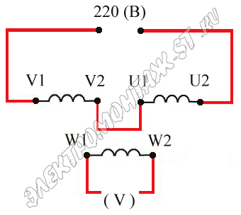 We connect the terminals of the windings U2 and V1 to each other, and apply a voltage of 220 volts to the terminals U1 and V2.
Then we measure the voltage at the terminals of the winding W1 and W2, in the first case it turned out to be 0.15 Volts. The resulting voltage is very small, so we can conclude that the windings are connected in opposite directions. We turn off the voltage and change the conclusions V1 and V2 in places.
After repeated measurement, 6.8 volts are obtained. So the windings are connected correctly, and their marking is correct (fig.1) .
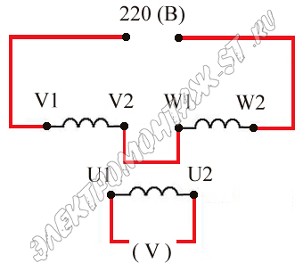 In a similar way, we look for the beginning and end of the winding with terminals W1 and W2, all connections are made according to the diagram below (fig.2)
.
In a similar way, we look for the beginning and end of the winding with terminals W1 and W2, all connections are made according to the diagram below (fig.2)
.
If, when measuring voltage, you received 6.8 Volts, then the marking and connection of the windings is correct.
After starting the electric motor, it is necessary to pay attention to the direction of rotation of the shaft and, if necessary, change the phases in places to change it.
Materials close
We advise you to read
, diagnosis, treatment Treatment of urogenital chlamydia") Urogenital chlamydia - description, causes, symptoms (signs), diagnosis, treatment Treatment of urogenital chlamydia
Urogenital chlamydia - description, causes, symptoms (signs), diagnosis, treatment Treatment of urogenital chlamydia The benefits and significance of hydroamino acid threonine for the human body L threonine what
 To wait or not to wait for a guy from the army For what reason can they be commissioned from the army
 Baked apples with cottage cheese Baked apples with cottage cheese

