AC chokes are widely used in various electrical installations and in the circuits of radio devices, for example, in ballast, current-limiting, in antenna circuits of powerful generators, in bandpass filters of powerful amplifiers, etc. Wide application recently chokes have found a modeling technique.
Chokes are made to be included in electrical circuits with power from several voltamperes to with inductance from 0.01 to currents from up to 10 a. Choke insulation is designed for various meanings permissible operating voltage - up to 2500 V for low-voltage and higher for high-voltage. In the following, only low-voltage single-phase chokes are considered.
The inductor is basically a coil with a ferromagnetic core that is flowed around with alternating current. The latter sharply increases the magnetic field. With the same parameters, a choke with a ferromagnetic core is incomparably more compact than a coil without a core. We emphasize that, other things being equal, inductive reactance the greater the choke, the better the magnetic properties of the ferromagnet, i.e., the greater its magnetic permeability.
All characteristics of the inductor are determined by the properties of its ferromagnetic core.
The current-voltage characteristics in this case can be close to linear, and can be significantly non-linear.
The properties of a non-linear choke are different from those of a linear choke. So, at a given frequency, the resistance of a non-linear inductor is a non-constant value, depending on the magnitude of the applied voltage. Typically, the inductive reactance of the inductor is much less with a saturated than with an unsaturated core. The shape of the curve of the current flowing through the winding of a non-linear choke depends on the shape of the curve of the applied voltage and on its magnitude. If the voltage is sinusoidal and the core is unsaturated, then the shape of the current curve is almost sinusoidal, with a saturated closed core, the current is non-sinusoidal.
The non-linearity of the throttle in some cases is an undesirable factor. At the same time, it determines the use of a choke in some devices of modern automation and radio electronics.
Some linearization of the current-voltage characteristic of the inductor can be obtained if its magnetic circuit is made with a non-magnetic gap. The inductor in this case becomes a limitedly linear element, the inductive resistance of which is constant when the current of the inductor changes within certain limits.
The use of a non-magnetic gap is also advisable to obtain more magnetic energy in the inductor. The magnetic circuits of the chokes of electronic equipment usually have these gaps. The non-magnetic gap introduces a number of features into the operation of the throttle. In particular, with it, the phenomenon of “broadening”, or “buckling”, of the magnetic flux is also observed. It should be pointed out that even a large gap in the magnetic circuit does not make the inductor a completely linear element, since Electric Energy, spent to cover the losses in the core, is not proportional to the square of the current. When designing close to linear chokes, one inevitably has to take into account the non-linearity of the ferromagnetic core.
In principle, three types of chokes should be distinguished: simple AC chokes, often called ferromagnetic core inductors, smoothing chokes for rectifiers, and controlled chokes, or saturation chokes.
Only simple single-phase low-power AC chokes are considered below.
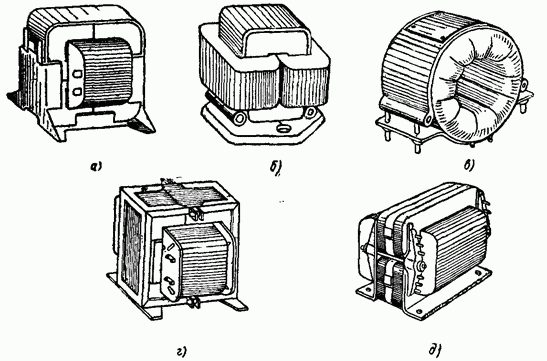
Rice. 1.1. Typical designs of open-type single-phase chokes: a - armored with a tape magnetic circuit; b - rod with tape cores and two coils; c - toroidal; g - bromine with a core of stamped plates; d - armored with plastic mounts.
Chokes, depending on the operating conditions of the equipment for which they are intended, can be divided into three groups:
a) chokes for equipment operating under normal conditions (temperature humidity);
b) chokes for short-term operation under conditions other than normal;
c) chokes for electronic equipment operating for a long time in difficult conditions - at high temperatures environment(up to) or in a tropical climate at a humidity of 98% and a temperature of 40 ° C. Chokes of the first group have, as a rule, open structure, the second group - open, waterproof and the third - closed, usually sealed. The most typical open-type chokes are shown in fig. 1.1.
AC chokes are usually divided according to the following criteria:
a) in terms of power - low-power (up to) and powerful (over);
b) by frequency - industrial (50 Hz), increased (400-1000 Hz) and high (over 1000 Hz);
c) according to the design of the power line - armored, rod and toroidal (in armored chokes, the core covers the winding, and in others - vice versa);

Rice. 1.2. Schematic representations of three types of chokes: a - with a closed ferromagnetic core; b - with a magnetic circuit having a gap; c - with an open magnetic circuit.
d) according to the design of the windings - coil, biscuit, etc.;
e) according to the type of core material - from electrical steel or from ferrite;
f) according to the material of the winding - from a wire or from a foil;
g) by design - open; open, but waterproof and closed.
Inductors can also be distinguished by the way the magnetic circuit is made: with a closed ferromagnetic core;
with magnetic circuits having non-magnetic gaps, and, finally, with completely open magnetic circuits (Fig. 1.2). The latter are not discussed in this book.
Inductors can also be subdivided according to the type of ampere characteristic: linearized - with a gap in the magnetic circuit or with an unsaturated closed core, and non-linear - without a gap in a saturated magnetic circuit or with a highly saturated core with a gap. The non-linearity of the throttle is sometimes regulated: quadratic, power, etc.
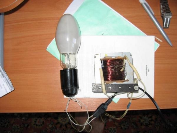
No fluorescent discharge lamp (household or office lamp, Street light) will not work without a throttle. This is a kind of quencher or voltage limiter, which is fed into the bulb of a gas-discharge lamp. Or rather, on its electrodes. In principle, this word is translated from German. But this is not the only function of this device. The inductor also creates a starting voltage, which is necessary for the formation of an electric discharge between the electrodes. This is how it ignites luminescent source Sveta. By the way, the starting voltage is short-term, lasting a fraction of a second. So, a choke is a device that is responsible for both turning on the lamp and for its normal work.
Throttle - a device responsible for the normal operation of lamps
Principle of operation
It is necessary to immediately make a reservation that the principle of operation of this device is based on the self-induction of the coil. If we consider the choke device, then this is an ordinary coil that works like an electrical transformer. That is, you can safely use the term choke transformer in a conversation. Although the design contains only one winding.
In fact, the coil is a core of steel or ferromagnetic plates that are isolated from each other. This is done specifically so that Foucault currents do not form, which create great interference. This coil has a very high inductance. At the same time, it actually acts as a powerful restraining barrier when the voltage in the network decreases, and especially when it grows strongly.

But it is this design that is considered low-frequency. Why does she have such a name? The thing is that the alternating current that flows in household networks- this is a wide range of fluctuations: from one to a billion hertz and above. The limits of the range are very large, therefore, purely conditionally, fluctuations are divided into three groups:
- Low frequencies, they are also called sound, have a range of oscillations from 20 Hz to 20 kHz.
- Ultrasonic frequencies: 20 kHz to 100 kHz.
- Ultra high frequencies: over 100 kHz.
So the above design is a low-frequency choke transformer. As for high-frequency devices, their design is distinguished by the absence of a core. Instead of them, as the basis of winding copper wire, plastic frames or conventional resistors are used. In this case, the choke transformer itself is a sectional (multilayer) winding.
 According to the device, the choke is an ordinary coil that works like an electrical transformer.
Chokes are very carefully calculated according to the set parameters that will support the operation of the lamps. daylight. This is especially true of the beginning of the glow, where it is necessary to pierce the gaseous medium with a discharge. Required here high voltage. After that, the device, on the contrary, becomes a restraining device. After all, in order for the lamp to glow, a lot of voltage is not needed. Hence the cost-effectiveness of lamps of this type.
Choke core
The core material is also represented by several items. His choice underlies the dimensions of the throttle itself. For example, a magnetic core is an opportunity to reduce the size of the inductor to a minimum. In this case, the inductance indicators do not change.
The best option for high-frequency devices is cores made of magnetodielectric alloys or ferrite. By the way, it is alloys that make it possible to use cores of this type in almost all ranges.
Characteristics
It is necessary to choose a transformer choke according to several characteristics, the main of which is inductance (measured in Henry H). But besides this, there are others:
- Resistance. Taken into account at direct current.
- Voltage change (permissible).
- Bias current, nominal value applies.
Type of chokes
Fluorescent lamps are presented on the market in a large assortment. And each type of fluorescent lamp has its own choke transformer. For example, a DRL and DNAT lamp cannot be ignited from the same type of throttle. It's all about the different parameters of starting and maintaining combustion. Here, the voltage is different, and the current strength.
But the MGL lamp can also work from the throttle DRL lamps, and from DNAT. But there is one moment. The brightness of the glow of this light source will depend on the applied voltage. Yes and Colorful temperature will be different.
Attention! Any inductor transformer in terms of service life will “survive” several lamps. Of course, with the reservation that the operation of the lamp is carried out correctly.

But you have to take into account the fact that the lamp "ages" over the years. On tungsten electrodes fluorescent lamps daylight, a special alkali metal paste is applied. So this paste gradually evaporates, the electrodes are exposed, which means that the voltage rises, which leads to overheating of the inductor. The end result can be two options:
- There will be a break in the coil winding, which will turn off the voltage supply to the electrodes.
- The coil will close. And this is the connection of the lamp directly to the AC mains. The lamp will burn out - that's for sure, or it may explode, which will lead to damage to the lamp as a whole.
Therefore, advice - do not wait until the lamp itself burns out. There is a special replacement schedule, which is determined by the manufacturer, and which must be strictly adhered to. Experienced electricians during preventive maintenance must check these lighting devices for a voltage parameter. If it approaches the limit of the norm, then the lamp is changed even before the service life. It is better to replace an inexpensive lamp than an expensive inductor transformer.

We add that manufacturers today offer improved protection systems for fluorescent lamps. Safety circuit breakers were added to their design, which are triggered by an increase in voltage inside the gas-discharge light source.
Separation by purpose
In fact, all chokes are divided into two main groups, like the lamps in which they are installed.
- Single-phase. They are used in household and office lamps with a connection to a 220 volt network.
- Three-phase. Connect to a 380 volt network. These include DRL and DNAT lamps.
According to the place of installation, these devices are also divided into two groups:
- Embedded. They are also called open. Such chokes are installed in the lamp housing, which protects it from moisture, dust, and wind.
- Closed (sealed, waterproof). These devices have a special box that protects them. Such models can be installed outdoors under the open sky.
Electronic analogues
The bulk of the chokes are fairly large devices. To reduce their size, but at the same time not change the parameters, it is necessary to replace the inductor with a semiconductor stabilizer, which, in principle, is a high-power transistor. That is, in the end, an electronic choke is obtained.
In fact, the installed transistor stabilizes voltage surges (fluctuations), reduces its ripple. But you have to take into account the fact that the electronic choke is still a semiconductor device. So it makes no sense to use it in high-frequency devices.
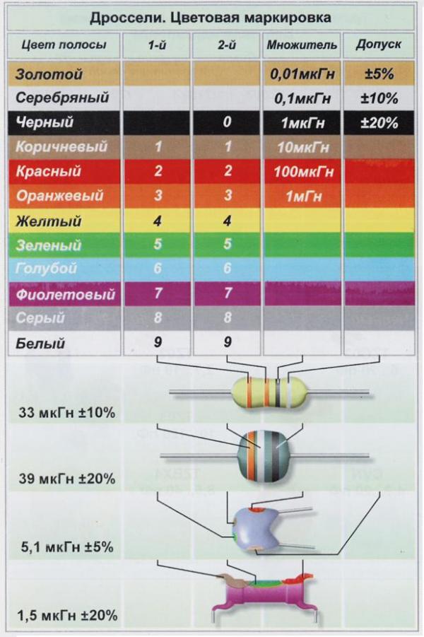
Like many electronic devices, chokes are marked depending on their parameters. This is a rather complicated abbreviation that will be incomprehensible to inexperienced electricians. Therefore, color coding was introduced. That is, several colored rings are applied on the device, which determine the inductance of the device. The first two rings are the nominal inductance, the third is the multiplier, the fourth is the tolerance.
Attention! If there are only three colored rings on the throttle, then by default it is assumed that its tolerance is 20%.
Color coding is convenient, especially for those who are starting to understand the field of electrics. With its help, you can accurately select the parameters of the installed devices (transistor, electronic choke, resistor, and so on).
Conclusion on the topic
So, we have determined the value of the throttle, its device, principle of operation and classification. As practice shows, this device can work for decades if the lamp itself is properly operated. Even the largest voltage surges are perfectly damped by the choke. And, therefore, the lamp will shine for a long time and without problems.
Related posts:
This material is about various types windings manufactured by the industry winding products.
An increase in the operating frequency and power of the converters leads to the fact that the number of turns of the transformer decreases, and they cannot fill the entire layer along the width of the winding. In this case, instead of winding wire it is better to use foil, and its width is chosen in such a way as to fill the entire layer in width. This is necessary in order to reduce the leakage inductance of the winding. The number of foil layers coincides with the number of turns and it remains only to choose the thickness of the foil. In low frequency transducers, the foil thickness can be chosen to fill the entire window. This reduces the ohmic resistance of the winding and, consequently, the losses in it. However, in high frequency converters this rule is no longer valid due to the skin effect. When evaluating the influence of the skin effect, it is necessary to take into account the shape of the current, which in some converter topologies can differ significantly from the sinusoidal one, for example in a bridge converter (see Fig. rice. one). The value of inductance and capacitance of the filter in this figure is chosen for the input and output values shown for current and voltage shown there.

Rice. 1. Bridge converter
Rice. 2. Transformer window on EC70 core
On the figure 2 the transformer window is shown on an EC70 core, the primary and secondary windings consist of four layers of foil each. The figure shows that the winding fills the entire window, but it is unlikely that in a real high-frequency transformer the number of layers and the thickness of the foil are so large as to fill the entire window.
Before choosing the thickness of the foil, it is necessary to determine the currents in the windings and the harmonic content of the current. The best way to do this is with a simulator and at the same time make sure that there are no pronounced oscillations in the converter in the steady state with a closed feedback loop. Simulation can be done, for example, using POWER 4-5-6
. The graphs show the results of the simulation.
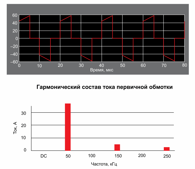
Rice. 3. Current waveform primary winding bridge transformer
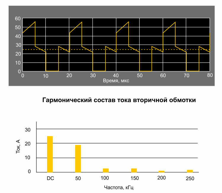
On the Figure 3 shows the current of the primary winding of the bridge transformer (see Fig. rice. one) and its harmonic content at maximum input voltage and maximum load. Of course, there is no direct current component, the frequency of the fundamental harmonic is 50 kHz. In addition, the spectrum contains two odd harmonics with a frequency of 150 and 250 kHz. On the figure 4 shows the current of one of the secondary half-windings. The filter inductance current is given in figure 5. Highest value has a constant component and a current ripple with a double operating frequency.
Rice. 4. Current of the secondary half-winding of the bridge transformer

Rice. 5. Bridge filter inductance current
The choice of foil thickness depends on the magnitude of the DC component of the current and the value of the harmonics of the AC components, as well as on the magnitude of the allowable losses in the windings.
Mathematical methods of analysis are complex and do not have an analytical solution. Can be used for analysis Dowell curves , but this method is rather tedious and cumbersome.

Rice. 6. Results of calculation on the simulator
The calculation results are presented on figure 6. It shows graphs of loss versus foil thickness for the primary and secondary windings of the transformer and for the winding of the filter inductor. Note that the graphs for the transformer windings have extrema of the minimum type, but for the inductor winding they do not.
For the primary winding of the transformer, the minimum losses are observed at a foil thickness of 0.35 of the penetration depth, which is about 0.2 mm. Since the currents secondary winding contain a significant DC component, for the secondary winding the nominal foil thickness is greater than and equal to about half the penetration depth at an operating frequency of 50 kHz.
Rice. Fig. 7. Transformer window with foil winding with a thickness selected according to the calculation results
On the figure 7 shows a transformer window with a foil winding with the thickness indicated above. As you can see, the window filling is less than 20%. With a small filling of the window, the leakage inductance increases. To reduce it, it is possible to complicate the winding by alternating the primary and secondary layers. However, in this case, firstly, the cost will increase, and secondly, the throughput capacity will increase. You can also use the sandwich winding method .
Since the inductor winding is different from the transformer winding, because In the inductor winding, mainly direct current flows, it is possible to increase the thickness of the winding foil and minimize losses in it. In this case, the foil thickness was chosen to be 0.7 mm, which is 3.4 times the penetration thickness at 100 kHz. In this case, the choke window with the RM12 core is completely filled.
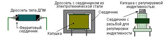
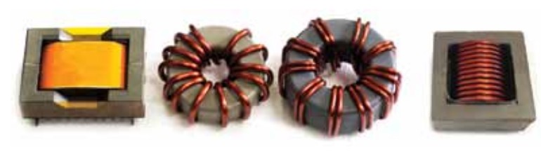
The design of chokes is quite diverse. The choice of choke type depends on the application. In addition to the obvious parameters - inductance, maximum current, saturation current, it is also necessary to take into account the harmonic composition of currents, because inductor losses alternating current significantly higher than the losses at direct current.
If a choke is needed for the circuit direct current where the amount of current ripple is small, you can use a drum core choke (drum core). It got its name because of the external resemblance to the corresponding percussion instrument. The low-profile core of such a choke consists of two flat discs on top and bottom and a narrow rod between them. The design feature provides more current without core saturation than in a toroidal choke.
Rice. 8. Choke with drum core
However, as can be seen from figure 8, which shows a core with a winding, the use of such a choke in an alternating or direct current circuit with large ripples is undesirable, since the alternating current losses are high due to the proximity effect in a multilayer winding.
Such chokes are currently manufactured by many companies. Among them is Ferroxcube, a little-known company in Russia that produces miniature drum-type cores with a height of 0.8-3 mm and a diameter of 3.5-8 mm from a new type of ferrite ZS92 . The maximum frequency for which this material is designed reaches 400 kHz, the saturation induction at 25 ° C is 0.47 T, and the power density at 100 ° C, a frequency of 100 kHz and an induction of 0.2 T reaches 350 kW / m 3.
But the main "highlight" of this ferrite is its good temperature properties. At a temperature of 175°C, the inductance of a choke with such a core will only halve, while for traditional MnZn ferrites it will drop to 10% of the initial one. The advantages of ZS92 ferrites over traditional ones begin to appear at a temperature of about 120°C.
Rice. 9. Inductors tested in the West Coast Magnetics experiment
In today's converters, a foil-coiled choke is often used (see far right choke on rice. 9). A choke with such a winding is considered in detail in . In the same place, a comparative calculation of the parameters of chokes with a spiral foil winding and a choke with a traditional foil winding was carried out.
From this calculation it follows that at a frequency of 400 kHz, the ratio between the winding resistance at alternating and direct currents for a spiral wound choke is R AC \u003d 20.2R DC, and for a conventional foil wound choke R AC \u003d] 0] R DC. In this case, in the first case, the resistance value was approximately 11.6 mOhm, and in the second case, it exceeded 62 mOhm. The advantage of the spiral wound choke is explained long distance between layers. In the example above, it was 4 mm, which is about 38 times the penetration depth at 400 kHz. In this case, the proximity effect is practically not manifested, therefore, the resistance of the winding on alternating current decreases.
The advantage of a spiral wound inductor is also confirmed in. In this work, chokes for the power factor corrector were investigated. Helical-wound chokes, conventional foil-wound chokes, and wire-wound chokes have been tested. The minimum resistance R DC \u003d 2.92 mOhm turned out to be in a choke with a spiral winding, for the other two chokes, the resistance value was 3.92 mOhm. In all cases, the windings consisted of 16 turns.
An interesting experiment was conducted at West Coast Magnetics . The engineers of this company conducted comparative tests of four types of chokes (see. rice. 9), designed for converters with a power of 1-100 kW. From left to right in this figure, the following devices are located.
Inductor on an E-shaped core with a gap of zinc ferrite with a winding of six layers of copper foil, made according to the company's proprietary technology. The initial magnetic permeability of the ferrite is 2000. The cross-sectional area of the inductor winding is 31600 circular mils (circular mil equals the area of a circle with a diameter of 1 mil, or 5.07-10 -4 mm2).
- Low permeability iron-nickel toroidal choke with 13 turns of 10 AWG wire.
- Iron-nickel toroidal choke with a high iron content and bifilar wound 10 turns of 7 AWG wire.
- Purchased chokes with a flat spiral winding. Two chokes of this type were used in the experiment: with 22 turns and a winding cross section of 22600 circular mils and with 12 turns with a winding cross section of 38200 circular mils. The tests were carried out at a current
65 A, the minimum inductance of the chokes at this current was at least 10 μH. The test circuit was quite simple - a resonant LC circuit: in parallel with the inductor, two capacitors connected in series with a capacity of 0.1 F were connected with a small equivalent series resistance(ESR). The results of the experiment are shown in Figure 10 with graphs of the losses in the inductor depending on the amplitude of the current ripples at frequencies of 100 and 250 kHz. In this figure, the following notation for graphs is adopted.
1 - choke on a W-shaped core;
2 - inductor on a toroidal core with a high iron content;
3 - choke with a spiral winding of 12 turns;
4 - choke on a toroidal iron-nickel alloy core;
5 - choke with a spiral winding of 22 turns.
As can be seen from the results of the experiment, the smallest losses were observed in the choke, manufactured using the proprietary technology of West Coast Magnetics. Good results with a small amplitude of ripples and with a choke with a spiral winding of 12 turns, however, with an increase in the amplitude of pulsations, it begins to yield to chokes on toroidal cores. Large losses in a choke with a spiral winding of 22 turns are understandable - with an increase in their number, the distance between the layers decreased and the influence of the proximity effect increased.
Note that in two of the three examples given in the article, the helical-wound choke outperformed the traditional foil-wound choke. However, in these examples, the comparison was carried out according to the resistance of the windings on alternating and direct currents, and in the third example, it was a full-scale experiment in which the chokes were tested in a working circuit, i.e. In addition to losses in the winding, losses in the core were also taken into account. In addition, chokes with a different number of turns took part in the tests, and the West Coast Magnetics choke had the smallest number, which, most likely, largely predetermined its results.
Based on the testing of chokes from various manufacturers, it is not yet possible to draw a conclusion about the advantage of one or another type of winding. For example, Coilcraft's latest helical-wound chokes, which have not been tested, look very promising.
Nevertheless, certain conclusions can be drawn from this article.
Low profile drum core chokes are best used in DC circuits with low ripple amplitude.
- Flat spiral wound chokes are suitable for use in circuits where the current ripple does not exceed 5-10%.
- In circuits with a large ripple amplitude, for example in resonant converters, it is desirable to use chokes with a large core height, because this reduces the number of winding layers. Winning in the tests of West Coast Magnetics inductor of its own design is largely due to the smallest number of winding layers - six.
- If a core with a non-magnetic gap is used, then in order to avoid edge effects, it is desirable to remove this gap away from the winding conductors.
We advise you to read
 Healthy eating scenario "Vitamins visiting children
 How to quickly and easily wake up in the morning - easy and effective tips
 Psychological characteristics of children in adolescence
 Transferring a child to another school - the procedure and necessary documents Whether to transfer a child to another school