The impressive power of an asynchronous electric motor, which transforms electricity into rotational energy, is not created due to any mechanical components: for such a powerful rotation, only electromagnets are used in its “stuffing”.
Induction motor rotor: design
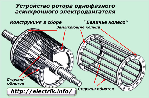
Rotor - an element of an electric motor rotating inside the stator (fixed component), the shaft of which is connected to the parts of working units, for example, saws, turbines and pumps. The laminated core is made from individual plates of electrical steel with semi-closed or open slots.
The motor is an electromechanical device that converts electrical energy into mechanical energy. and a three-phase motor running at synchronous speed is called a synchronous motor. When two opposite poles come close to each other, if the magnets are strong, there is a huge force of attraction between the two poles. In this state, two magnets are called magnetic.
Principle of synchronous rotation
How does the rotor rotate at synchronous speed? Now, to understand the concept of synchronous motor operation, consider a two-pole simple rotor. The synchronous motor is a double excited machine with two electrical inputs attached. Therefore, a synchronous motor rotates at one and only one speed, i.e. synchronous speed. But all this depends on the presence of magnetic locking between the stator and rotor poles. It is virtually impossible for the stator poles to pull the rotor poles from their stationary position into a magnetically latched state. this is the reason why synchronous motors do not start themselves.
The massive rotor is a solid steel cylinder placed inside the stator, with a core pressed onto its surface.
Contactless, not connected to any external electrical circuit the rotor winding creates torque and is of two types:
- short-circuited (short-circuited rotor);
- phase (phase rotor).
squirrel-cage rotor
Highly conductive copper rods (for machines of high power) or aluminum rods (for machines of lower power) soldered or poured into the surface of the core and short-circuited from the ends with two rings play the role of electromagnets with poles facing the stator. This design is called the "squirrel cage", given to it by the Russian electrical engineer M. O. Dolivo-Dobrovolsky.
Methods for starting a synchronous motor. After a while, when magnetic blocking occurs, the supply to the external motor is cut off from the clutch. Application of synchronous motors. It is used where high power at constant speed is required.
Because a synchronous motor is capable of both leading and lagging power factors, it can be used to improve the power factor. An unloaded synchronous motor with a leading power factor is connected in a power system where static capacitors cannot be used.
The winding rods do not have any insulation, since the voltage in such a winding is zero. More commonly used for medium power motor rods, easy-melting aluminum is characterized by low density and high electrical conductivity. To reduce the higher harmonics of the electromotive force (EMF) and eliminate ripple magnetic field, the rotor rods have a certain calculated angle of inclination relative to the axis of rotation.
Rotary rotor induction motor design
The synchronous motor finds application where the operating speed is lower and high power is required. In my last article, we discussed which type. This engine is the one that uses the wound rotor. Rotary rotor asynchronous motor is also known as asynchronous motor slip. As with other induction motors, the main parts are the stator and rotor. The stator of this motor is the same as in induction motors with squirrel-cage rotor. The rotor is the part that makes it different from other induction motors.
In low-power engines, the core grooves are usually closed: separating the rotor from the air gap - a steel plate allows you to additionally fix the windings, but at the expense of some increase in their inductive resistance.
phase rotor
It is characterized by practically no different from the three-phase stator winding (in more general case- multi-phase) winding laid in the grooves of the core, the ends of which are connected according to the "star" scheme. The winding leads are connected to contact rings fixed on the rotor shaft, to which, when the engine is started, stationary graphite or metal-graphite brushes connected to the rheostat are pressed and slide.
Wound rotator induction motor stator
Let me give you a brief introduction to the stator and then tell you about the structure of the rotor.
Wound rotator induction motor rotor
In a rotary rotor induction motor, the rotor has three-phase winding similar to the stator winding. The winding is placed evenly on the grooves of the rotor. connected with 3 slip rings. It's all about the construction of the rotor. Now let's discuss how it works.Operation of an induction motor with a wound rotor
The stator magnetic field and the rotor magnetic field interact and result in a torque that will turn the rotor.- The rotor is also cylindrical and has winding holes.
- These slip rings are mounted on the shaft.
- Each phase is connected to one of the three slip rings.
- These slip rings are connected to the brushes.
- The three slip rings rotate with the rotor while the hands remain stationary.
- This magnetic field is called the magnetic field of the rotor.
To limit the resulting eddy currents, an oxide film applied to the surface of the windings is usually sufficient, instead of insulating varnishes.
A three-phase starting or adjusting resistor added to the rotor winding circuit allows you to change the active resistance of the rotor circuit, helping to reduce high starting currents. Rheostats can be used:
Speed and torque can be controlled in these motors by changing the resistance. Some of the characteristics of rotary rotor induction motors are presented below. Wound Rotor induction motor requires extra maintenance due to slip and brushes. This motor consumes less current at start compared to squirrel-cage induction motors. The rotary rotor induction motor is less efficient than squirrel-cage induction motors.
- You can control the speed of these motors.
- The moment can also be controlled.
- These motors have high starting torque.
- Such motors are more expensive than other induction motors.
- Maintenance costs are also taken into account.
- These motors have a low power factor.
- metal wire or stepped - with manual or automatic switching from one resistance level to another;
- liquid, the resistance of which is regulated by the depth of immersion in the electrolyte of the electrodes.
To increase the durability of the brushes, some models of phase rotors are equipped with a special squirrel-cage mechanism that raises the brushes after starting the motor and closes the rings.
And where squirrel-cage induction motors cannot be used due to their high starting currents. The wound rotor induction motor is used in applications requiring soft start and variable speed. Some of the applications for this engine include cranes, mills, hoists and conveyors. The rotary rotor induction motor is also used in fans, blowers and mixers. They are used in large pumps in the water industry.
- They are used in places where high starting torque is required.
- These motors are used with high inertial loads.
Asynchronous motors with a phase rotor are characterized by a more complex design than with a squirrel-cage, but at the same time, more optimal starting and control characteristics.
Principle of operation
The stator electromagnets are located close to the rotor bars and transmit electricity to them to rotate it. The magnetic field induced in the rotor will follow the magnetic field of the stator, thus carrying out the mechanical rotation of the rotor shaft and associated units. At the same time, the electromagnetic induction created by the stator coils pushes the current on the rods strictly away from itself. The value of the current in the rods changes with time.
They are used in a variety of industrial applications but can be protected from various hazards such as mechanical electrical faults to help their purposes. This article discusses the system for protecting asynchronous motors from occurring failures. This motor is experiencing Various types electrical faults such as overvoltage, under voltage, overload, unbalanced voltage, phase ground fault and single phase. These electrical faults cause the motor windings to heat up, resulting in reduced motor life.
Write comments, additions to the article, maybe I missed something. Take a look at, I will be glad if you find something else useful on my site. All the best.
The very name of this electrical device indicates that Electric Energy, which arrives at it, is converted into rotary motion rotor. Moreover, the adjective "asynchronous" characterizes the discrepancy, the lag of the armature rotation speeds from the stator magnetic field.
The degree of an induction motor depends on the costs and features of the motor. The directional system is designed to protect the asynchronous motor from overheating and single-phase. The protection system using multiple motors for production is very important in industries.
The main design plan for this project is to ensure safety in the industries. If the motor temperature during the process exceeds the threshold value, the motor stops without delay. The system uses a 3-phase power supply to which 3-phase transformers are connected. If any of the phases is not available, then the equivalent transformer ends, supplying power to the circuit.
The word "single-phase" causes an ambiguous definition. This is due to the fact that in electrics it determines several phenomena:
shift, angle difference between vector quantities;
potential conductor two, three or four-wire electrical circuit alternating current;
one of the stator or rotor windings three-phase motor or a generator.
The main relay is powered through a set of 4-relays, which are disconnected due to the fact that one relay is not controlled by the power supply. Thus, the main relay provides three-phase power to the motor, which is switched off. The thermistor is connected to the body of the induction motor to sense the temperature. If the temperature rises, the 4th relay is de-energized.
Further, this design can be developed using current sensors for overload protection and a phase sequence sensor to protect the motor from incorrect phase sequence. Thus, all this concerns the protection system of asynchronous motors. We hope you understand this concept better.
Therefore, we immediately clarify that single-phase electric motor it is customary to call the one that works from two-wire network alternating current, represented by phase and zero potential. The number of windings mounted in various stator designs does not affect this determination.
Motor design
According to its technical device, an asynchronous motor consists of:
The use of a phase-shifting winding in the stator
Its main characteristics are: Reliability Low cost of acquisition and maintenance Possibility of speed control. Pumps and compressors Fans Milling machines Treadmills, conveyors and elevators Grinders and grinders Saws, lathes and grinders.
The operation of all electric motors, including the three-phase asynchronous motor, is based on the magnetic field created by the electric current circulating in the windings of the machine. As for the three-phase induction motor, it has three windings in a structure called a stator.
1. stator - a static, fixed part, made by a body with various electrical elements located on it;
2. a rotor rotated by the forces of the electromagnetic field of the stator.
The mechanical connection of these two parts is made by rotation bearings, the inner rings of which are seated on the fitted sockets of the rotor shaft, and the outer rings are mounted in protective side covers fixed on the stator.
The resulting magnetic field generated by each electric current is of a rotating nature and at a constant speed. How can we find the resulting field? When a coil is driven by an electric current, a magnetic field is created along the axis of the coil and has a value proportional to the current.
The three-phase winding consists of three single-phase 120 ohm spacers. These fields are located at a distance of 120 degrees from each other. This magnetic field attracts a moving structure called a rotor, causing it to rotate. The synchronous speed of the rotating field is given as follows.
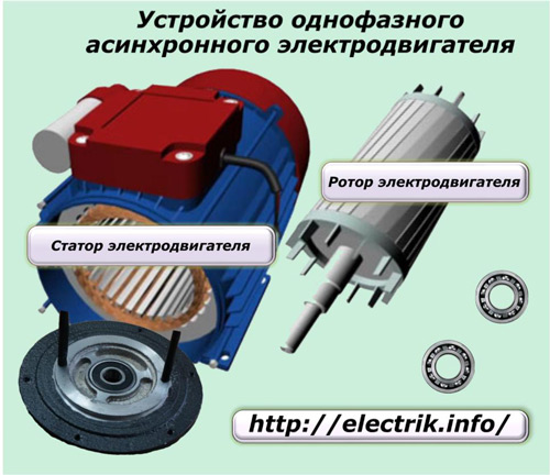
Rotor
Its device for these models is the same as for all asynchronous motors: a magnetic circuit is mounted on a steel shaft made of laminated plates based on soft iron alloys. On its outer surface, grooves are made into which winding rods made of aluminum or copper are mounted, shorted at the ends to the closing rings.
The most common pole values are 2, 4, 6 or 8 poles. The moving part, called the rotor, responsible for the transmission mechanical movement to a load such as an elevator. Obviously, all the devices that interest me are equipped with an asynchronous motor.
Principle and operation of an induction motor
What are the advantages of this type of engine? Here are some answers. The induction motor is a high performance motor often used in the fields of transportation, industry and household appliances. Consisting of two separate parts called rotor and stator, the induction motor owes its name to the difference in power measured on each of these parts. Indeed, although the stator rotates at a certain speed determined by the electric current, the rotor, meanwhile, generates its own magnetic field and has its own rotation speed, which is not proportional to the stator speed.
flows in the rotor winding electricity, induced by the magnetic field of the stator, and the magnetic circuit serves to good passing the magnetic flux created here.
Separate rotor designs for single-phase motors can be made of non-magnetic or ferromagnetic materials in the form of a cylinder.
Asynchronous motor and food processor
This difference, called the phase shift, is typically between 2 and 10%. The induction motor is widely used in the home appliance world, mainly for washing machines, dishwashers and dryers. This type of motor is very robust and provides relatively quiet operation. In the case of household robots, having an induction motor has an important advantage: because the two parts of the motor rotate at a different speed, the robot's blades can adapt their speed to the contents in the bowl itself when the device is running at full power.
stator
The stator design is also presented:
body;
magnetic circuit;
winding.
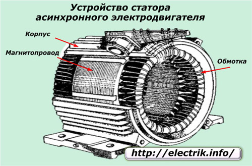
Its main purpose is to generate a stationary or rotating electromagnetic field.
The stator winding usually consists of two circuits:
In other words, the denser the cooking, the slower the robot turns, even if it is set to maximum power. The asynchronous motor also offers the possibility to adapt the speed of the device to the amount of products present in the container. In short: robots that have an asynchronous motor are intelligent robots. Another significant advantage: the asynchronous motor of home robots makes these devices quieter. Selection criterion for Sunday morning cooking without waking up the whole house!
1. worker;
2. launcher.
For the simplest designs, designed for manual unwinding of the armature, only one winding can be made.
The principle of operation of an asynchronous single-phase electric motor
In order to simplify the presentation of the material, let's imagine that the stator winding is made with just one turn of the loop. Its wires inside the stator are carried in a circle by 180 angular degrees. An alternating sinusoidal current passes through it, having positive and negative half-waves. It creates not a rotating, but a pulsating magnetic field.
How magnetic field pulsations occur
Let us analyze this process using the example of the flow of a positive current half-wave at times t1, t2, t3.
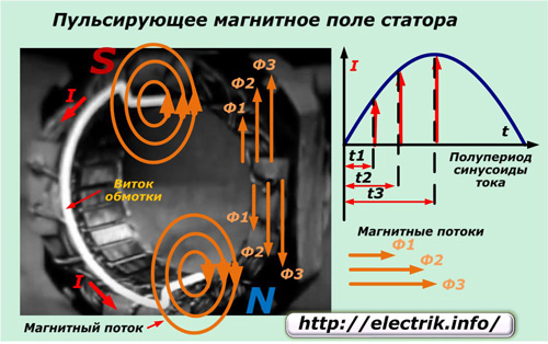
It runs along the upper part of the conductor towards us, and along the lower part away from us. In the perpendicular plane represented by the magnetic circuit, magnetic fluxes F arise around the conductor.
The currents changing in amplitude at the considered moments of time create electromagnetic fields of different magnitude F1, F2, F3. Since the current in the upper and lower half is the same, but the coil is bent, the magnetic fluxes of each part are directed oppositely and cancel each other's action. You can determine this by the rule of the gimlet or the right hand.
As you can see, with a positive half-wave of rotation, the magnetic field is not observed, but only its pulsation occurs in the upper and lower parts of the wire, which is also mutually balanced in the magnetic circuit. The same process occurs in the negative section of the sinusoid, when the currents change direction to the opposite.
Since there is no rotating magnetic field, the rotor will remain stationary, because there are no forces applied to it to start rotating.
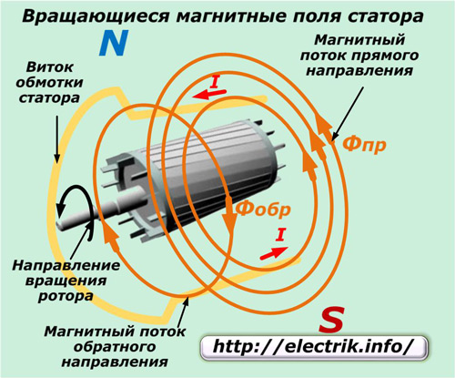
How the rotation of the rotor is created in a pulsating field
If we now give the rotor rotation, even if by hand, then it will continue this movement.
To explain this phenomenon, we show that the total magnetic flux changes in the frequency of the current sinusoid from zero to a maximum value in each half-cycle (with a change in direction to the opposite) and consists of two parts formed in the upper and lower branches, as shown in the figure.
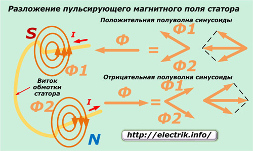
The magnetic pulsating field of the stator consists of two circular ones with amplitude Фmax/2 and moving in opposite directions with the same frequency.
npr=nrev=f60/p=1.
This formula indicates:
npr and nrev of the frequency of rotation of the stator magnetic field in the forward and reverse directions;
n1 is the speed of the rotating magnetic flux (rpm);
p is the number of pairs of poles;
f is the frequency of the current in the stator winding.
Now we will give the motor rotation by hand in one direction, and it will immediately pick up the movement due to the occurrence of a rotating moment caused by the sliding of the rotor relative to different magnetic fluxes of the forward and reverse directions.
We accept that the magnetic flux of the forward direction coincides with the rotation of the rotor, and the reverse, respectively, will be opposite. If we denote by n2 the frequency of rotation of the armature in rpm, then we can write the expression n2< n1.
In this case, we denote Spr \u003d (n1-n2) / n1 \u003d S.
Here, the indices S and Spr are the slips of the induction motor and the rotor of the relative magnetic flux of the forward direction.
For the reverse flow, the sliding Srev is expressed by a similar formula, but with a change of sign n2.
Srev \u003d (n1 - (-n2)) / n1 \u003d 2-Spr.
In accordance with the law of electromagnetic induction, under the action of direct and reverse magnetic fluxes in the rotor winding, electromotive force, which will create in it currents of the same directions I2pr and I2arr.
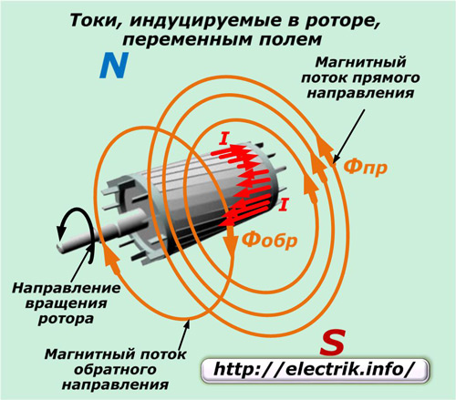
Their frequency (in hertz) will be directly proportional to the amount of slip.
f2pr=f1∙Spr;
f2rev=f1∙Srev.
Moreover, the frequency f2rev, formed by the induced current I2rev, significantly exceeds the frequency f2rev.
For example, the electric motor is running on a 50 Hz network with n1=1500 and n2=1440 rpm. Its rotor has slip relative to the forward direction magnetic flux Spr=0.04 and current frequency f2pr=2 Hz. Reverse slip Srev=1.96, and current frequency f2rev=98 Hz.
Based on Ampère's law, when the current I2pr interacts with the magnetic field Фpr, a torque Mpr will appear.
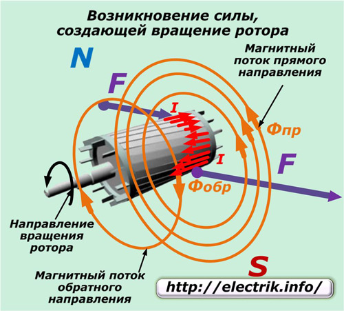
Mpr \u003d cm ∙ Fpr ∙ I2pr ∙cosφ2pr.
Here, the value of the constant coefficient cM depends on the design of the engine.
In this case, the reverse magnetic flux Mobr also acts, which is calculated by the expression:
Mobr \u003d cm ∙ Fabr ∙ I2 arr ∙ cosφ2 arr.
As a result of the interaction of these two flows, the resulting one will appear:
M= Mpr-Mobr.
Attention! When the rotor rotates, currents of different frequencies are induced in it, which create moments of forces with different directions. Therefore, the motor armature will rotate under the action of a pulsating magnetic field in the direction from which it began rotation.
During overcoming the rated load by a single-phase motor, a small slip is created with the main share of the direct torque Mpr. The counteraction of the braking, reverse magnetic field Mobr affects very little due to the difference in the frequencies of the currents of the forward and reverse directions.
f2reverse current significantly exceeds f2reverse, and the generated inductive reactance X2obr greatly exceeds the active component and provides a large demagnetizing effect of the reverse magnetic flux Fobre, which eventually decreases.
Since the power factor of the motor under load is small, the reverse magnetic flux cannot have a strong effect on the rotating rotor.
When one phase of the network is fed to a motor with a fixed rotor (n2=0), then both forward and reverse slips are equal to one, and the magnetic fields and forces of the forward and reverse flows are balanced and rotation does not occur. Therefore, it is impossible to unwind the armature of the electric motor from the supply of one phase.
How to quickly determine the engine speed:
How is the rotation of the rotor created in a single-phase asynchronous motor
Over the entire history of operation of such devices, the following design solutions have been developed:
1. manual spinning of the shaft by hand or cord;
2. the use of an additional winding connected at the time of launch due to ohmic, capacitive or inductive resistance;
3. splitting by a short-circuited magnetic coil of the stator magnetic circuit.
The first method was used in the initial development and was not used further due to the possible risks of injury during launch, although it does not require additional chains to be connected.
The use of a phase-shifting winding in a stator
To give the initial rotation of the rotor to the stator winding, in addition, at the time of launch, another auxiliary one is connected, but only shifted in angle by 90 degrees. It is performed with a thicker wire to pass larger currents than those flowing in the working one.
The connection diagram of such a motor is shown in the figure on the right.
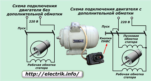
Here, a button of the PNVS type is used to turn on, which is specially designed for such engines and was widely used in the operation of washing machines manufactured in the USSR. This button immediately turns on 3 contacts in such a way that, after pressing and releasing, the two extreme ones remain fixed in the on state, and the middle one closes for a short time, and then returns to its original position under the action of the spring.
Closed extreme contacts can be turned off by pressing the adjacent "Stop" button.
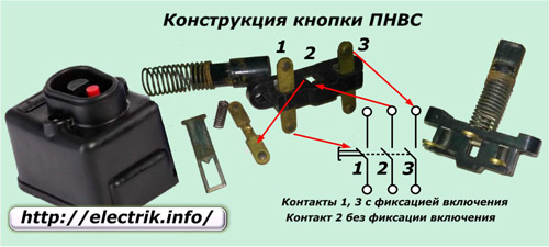
In addition to the push-button switch, to disable the additional winding in automatic mode, the following are used:
1. centrifugal switches;
2. differential or current relays;
To improve engine starting under load, additional elements in a phase-shifting winding.
In such a circuit, an ohmic resistance is mounted in series to the stator additional winding. In this case, the winding of the turns is carried out in a bifilar way, which ensures the coefficient of self-induction of the coil is very close to zero.
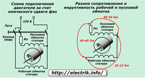
Due to the implementation of these two techniques, when currents pass through different windings, a phase shift of the order of 30 degrees occurs between them, which is quite enough. The angle difference is created by changing the complex resistances in each circuit.
With this method, there may also be starting winding with low inductance and high resistance. For this, winding with a small number of turns of wire of an underestimated cross section is used.
Capacitive phase shift of currents allows you to create a short-term connection of a winding with a series-connected capacitor. This circuit only works while the engine is on mode, and then turns off.
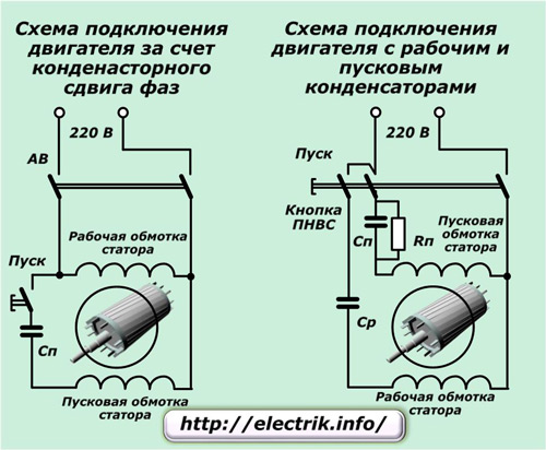
Capacitive starting produces more torque and higher power factor than resistive or inductive starting. It can reach 45÷50% of the nominal value.
In separate circuits, capacitance is also added to the chain of the working winding, which is constantly on. Due to this, currents in the windings are deflected by an angle of the order of π/2. At the same time, a shift in the amplitude maxima is very noticeable in the stator, which provides a good torque on the shaft.
Due to this technique, the engine is able to generate more power during start-up. However, this method is only used with heavy starting drives, for example, to spin the drum. washing machine filled with linen with water.
Capacitor start allows you to change the direction of rotation of the armature. To do this, just change the polarity of the connection of the starting or working winding.
Connecting a single-phase shaded pole motor
In asynchronous motors with a small power of about 100 W, splitting of the stator magnetic flux is used due to the inclusion of a short-circuited copper coil in the pole of the magnetic circuit.
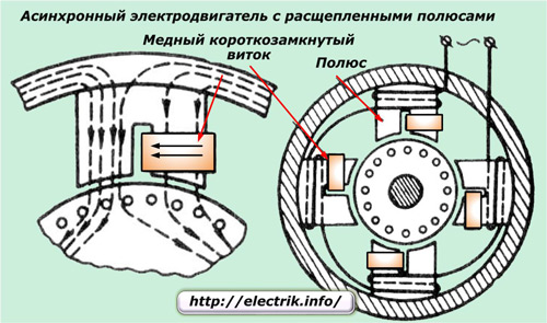
Such a pole cut into two parts creates an additional magnetic field, which is shifted from the main one along the angle and weakens it in the place covered by the coil. This creates an elliptical rotating field that generates a torque of constant direction.
In such designs, one can find magnetic shunts made of steel plates that close the edges of the tips of the stator poles.
Engines of similar designs can be found in fan devices for blowing air. They do not have the ability to reverse.
We advise you to read
 Record grain harvest will lead to deflation
 Record grain harvest will lead to deflation Grain harvest in a year
 The history of the appearance of the first knives and their development by era Make a stone knife with your own hands
 How to make a ceramic grindstone and sharpen a knife on it with your own hands DIY stone knife

