1) What are the consequences of increased voltage in the network?
All manufacturers of electrical equipment give an acceptable range of supply voltage changes, within which their equipment operates normally. For example, if the device can operate at a voltage of 220 V ± 10%, this means that the minimum supply voltage is 220 - 22 = 198 V, and the maximum is 220 + 22 = 242 V. It is clear that if the supply voltage is lower than 198 V or above 242 V, the developer cannot guarantee normal work of your device.
problem overvoltage easy enough to understand, because in all cases, whatever the type of consumer, overvoltage always leads to an increase in the current consumed. If the overvoltage is significant, or long in time, protecting the consumer from overheating is the task of thermal and electromagnetic safety devices. If the overvoltage is weak, short or rarely occurring, the consumer, as a rule, is not in danger.
On the other hand, if the overvoltage is very significant (for example, during a lightning discharge it can exceed many millions of volts), the surge in current strength can be such that the consumer burns out before the surge reacts to this surge.
If 24 V is applied to a 24 V / 3 W bulb (see Fig. 55.1), it lights up, consuming 3 W of power. However, if a voltage of 240 V is applied to it (that is, 10 times more), it instantly burns out. This is because the power consumption is proportional to the square of the voltage (P = U2 / R). Thus, by connecting a light bulb to a power source with a voltage of 10 times the nominal voltage, we make it absorb power increased by 100 times (that is, 300 watts, which corresponds to a small electric heater).
2) What are the consequences of a voltage drop in the network?
In the case of a voltage drop, the problem of determining the consequences is much more difficult, since the consequences depend on the type of electricity consumer. In general, two main categories of consumers can be distinguished: resistance type and motor type.
For resistance type consumer,
voltage drop always leads to an equivalent decrease in current consumption (recall Ohm's law: I \u003d U
So, at low voltage, the resistance consumes a weaker current, which is not
entails absolutely no danger
the severity of its damage. For example (see
rice. 55.2), a resistor consuming 300W at 240V will only consume 3W if it is energized at 24V! Of course, this can be very bad when it comes to, for example, an electric compressor crankcase heater!
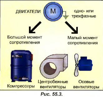
For the consumer of the engine type, it is necessary to distinguish between engines that drive devices with a large moment of resistance (see Fig. 55.3), for example, piston refrigeration compressors, and drive motors for mechanisms with a low resistance moment (for example, an axial fan, for which a light blow of wind is enough to rotate).
Centrifugal fans fall between these two categories, however, most of them have characteristics that make it difficult to withstand a noticeable drop in supply voltage. Therefore, they are usually classified as units with a large moment of resistance.
First of all, remember that the moment on the motor shaft, that is, its ability to set in motion any unit, depends on the square of the supply voltage.
So, if the motor is designed to operate at a voltage of 220 V, then in the event of a voltage drop to PO V (that is, 2 times less), its torque on the shaft will drop by 4 times (see Fig. 55.4).  If during the voltage drop the moment of resistance of the driven machine is very high (eg compressor), the motor stops. At the same time, it begins to consume a current equal to the starting current, and this occurs during the entire period of the forced stop. As a result, the motor overheats dangerously and one can only hope that the built-in protection or thermal protection relay will cut off the power very quickly.
On the other hand, if the moment of resistance of the driven device is low (for example, a small axial fan), a decrease in supply voltage causes a decrease in rotational speed, because the motor has less available power.
It is precisely this property that is used in most multi-speed motors that rotate fans in individual air conditioners (see Fig. 55.5).
In the HI (high speed) position, the resistance is short-circuited and 220 V is supplied to the motor. It rotates at rated speed.
In the MC (low speed) position, the resistance is in series with the motor winding, which causes a noticeable voltage drop across the motor. The torque on the shaft drops and the fan rotates at a reduced speed.
At the same time, the consumed current also decreases. This property is widely used in the manufacture of electronic speed controllers based on thyristors, specifically designed to control the condensation pressure by changing the speed of axial fans. installed in air-cooled condensers (see Fig. 55.6).
These regulators, sometimes called current valves or converters, operate, like most limiting regulators, on the principle of "cutting off" part of the amplitude alternating current.
Pos. I. High pressure condensation, the speed controller completely skips the mains half cycles. The voltage at the motor terminals (corresponding to the shaded area) is equal to the mains voltage and the motor rotates at maximum speed, consuming rated current.
Pos. 2. The condensing pressure drops and the regulator kicks in, cutting off a portion of each half-cycle entering the motor (in each half-cycle, it turns off the power for a short moment). The average voltage at the motor terminals drops (see shaded area) and the speed, as well as the current drawn, drop.
Pos. 3. If the medium voltage becomes so weak that the motor torque is less than the fan resistance torque, the motor stops and starts to heat up. Therefore, speed controllers are usually adjusted to the maximum allowable value of the minimum speed.
Note. The method of "cutting off" part of the AC amplitude can only be used when single phase motors designed to drive units with low resistance torque. If three-phase motors are involved (for driving machines with a high resistive moment), then multi-speed motors must be used (see section 65) or frequency converters, much more expensive and bulky, or engines direct current(these two types of equipment are used with "Inverter" type devices).
A voltage drop can also occur in the external power grid: we are well aware of the consequences of a short-term power outage or voltage drop, which leads to a decrease in the brightness of the lighting. We also know that it is necessary to follow the rules for selecting the size of the supply wires in order to limit the voltage drop across them to an acceptable value. However, sometimes the voltage drop can have other causes that are not directly related to voltage losses in the supply wires.
For example, the electromagnet coil of a 24 V relay (quite ordinary), which allows you to control a small contactor, shown in fig. 55.7, at the moment of operation of the electromagnet, it consumes a current of 3 A, and in the hold mode, the current consumed is 0.3 A (that is, 10 times less).
That is, the electromagnet, when turned on, consumes a current equal to ten times the current of the hold mode. Although the turn-on time is very short (about 20 ms), this can sometimes have a noticeable effect in large control circuits with many contactors or relays.
It contains 20 contactors, from C1 to C20 (since the page size is limited, contactors C2 to C19 are not shown in the diagram).
After turning off the current, all 20 contactors are in standby mode. As soon as the current turns on, they will work simultaneously.
Since each contactor consumes 3 A when activated, a current equal to 3 x 20 = 60A will flow through the secondary winding of the transformer!
If the secondary winding has a resistance of 0.3 ohms, then the voltage drop across it at the moment the contactors are activated will be 0.3 x 60 = 18 V. Then the supply voltage of the contactors will be only 6 V (see Fig. 55.9), and they may not work .
At the same time, both the transformer and the wiring will overheat, and the contactors will start to hum, but will not be able to switch to hold mode, which will continue until the fuse blows or the circuit breaker trips.
If the secondary winding of the transformer has a resistance of 0.2 ohm, at the moment the contactors are powered on, the voltage drop across it will be 0.2 x 60 = 12 V. In this case, the contactors will be powered only by 12 V instead of 24 V, and there is no way to claim that they will work no |jj| grounds. If they do not work, the current in the circuit will remain abnormally high, just as in the previous example.
The problem of resistance secondary winding explains why the no-load voltage at the output of a transformer is greater than the voltage under load. The greater the current drawn, the lower the output voltage. 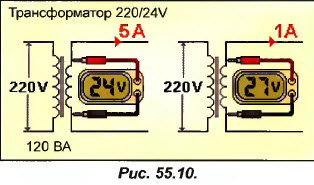
In the example in fig. 55.10 the 220/24 V transformer has a power of 120 VA and is supplied with a voltage of 220 V.
When the transformer is delivering 5A, measuring the output voltage gives us 24V (24 x 5 = 120VA).
However, when the drawn current drops to 1A, the output voltage rises, reaching, for example, 27V. This voltage is caused by the resistance of the secondary wire.
If the current drops, the output voltage rises. Conversely, if the current drawn is greater than 5 A, the output voltage drops below 24 V and the transformer begins to overheat (recall that heating depends on the square of the current).
So, too small a transformer can cause serious problems: so you can not neglect the selection of power transformers!
3) How to set up a thermal relay?
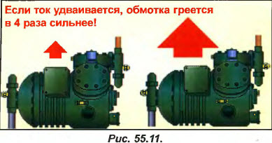
The thermal protection relay is primarily designed to protect the motor against minor but continuous overcurrent. Recall that the motor heats up in proportion to the square of the current consumed (P = R x I2). Thus, if the consumed current increases by 2 times (see Fig. 55.11), the heating of the motor increases by 4 times.
Of course, the ideal option for thermal protection would be such an option in which the motor would be very quickly disconnected from the network when the specified current value was exceeded. However, in this case, the thermal protection relay may operate in the starting mode, when the current strength, at some moments, can be 8 times higher than the nominal value. Therefore, the design used (based on three bimetallic plates) allows you to start the engine without unwanted shutdowns. This is achieved by installing a heating element in the thermal relay, which is selected taking into account the time required to turn off the motor depending on the current passing through the heating element. 
The curve in fig. 55.12 is built for the most favorable case, when the bimetal plates of the heating element are already hot (if these plates are cold, the trip time increases). For a thermal relay set to 10 A, there is no trip at all at 10 A, which seems to be quite normal. If the current rises to 15 A, the thermal relay will turn off the motor after about 80 seconds. At a current of 40 A, the trip will occur after 6 s, and at a current of 60 A, after 3 s.
Consider now a curve built for a relay set to the same 10 A, but for the case when a thermal relay must protect a three-phase motor in the event of a phase failure (the motor only works with two windings).
If the remaining two windings draw 10 A, the thermal relay will shut down the motor in approximately 240 seconds (4 minutes). If the current rises to 15 A, the trip will occur after about 40 seconds. At a current of 20 A, the thermal relay will take 18 seconds to turn off the engine, for 60 A - 3 seconds.
As you can see, a thermal relay set to 10 A, in case of anomalies, turns off the protected motor after a sufficiently long period of time.
Therefore, the thermal relay should never be set to a current value greater than the rated value (indicated on a plate attached to the motor housing).
It often happens that the motor draws less current than indicated on its case. This is because the current indicated on the case corresponds to the current consumed during nominal value power developed by the engine. For example, a compressor equipped with an air-cooled condenser draws less current in winter (lower condensing pressure) than in summer (higher condensing pressure). In this case, the thermal protection relay must be set to the maximum value of the absorbed current, however, not exceeding the current indicated on the housing (otherwise what is the motor rating plate for?).
In the engine presented, overheating is caused. At the same time, the thermal relay cannot respond to an abnormal increase in the temperature of the motor or its windings.
The same thing will happen if the finned motor housing becomes excessively dirty: the cooling of the windings will deteriorate and the motor will start to overheat. In this case, the thermal protection relay will also not be able to do anything, since the current consumption does not increase. Only the built-in thermal protection (provided by the developer) is able to detect a dangerous temperature rise and turn off the engine in time.
On the other hand, an increase in the current drawn by the motor can be caused by mechanical failures (for example, a seized bearing in the motor or driven machine). This increase in current (which will occur quite slowly, at the same rate as the increase in frictional force in the bearing), sooner or later, will cause the motor to trip by the thermal relay or the built-in thermal protection, if it exists (in this case, the motor is equipped with a dual system thermal safety, which can be all the more useful since the engine is the most important element of the installation).
To supplement our information about thermal relays, we recall that they perform their functions for each of the windings separately. This means that if 3 bimetallic strips heat up differently (for example, if one of the windings has a break, the other two heat up), the relay turns off the motor (see the curve in Fig. 55.13). 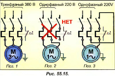
The function of a phase-to-phase differential relay, which is then performed by a thermal relay, provides undeniable advantages when used three-phase motor(see pos. 1 in fig. 55.15), however, requires a special wiring diagram in case of using a single-phase motor.
In fact, if you connect the relay as shown in pos. 2 fig. 55.15, the right plate will not heat up and a few minutes after the start of operation, the relay will turn off the engine.
That is, the relay must be connected in such a way that all three bimetallic plates pass the same current (see pos. 3 in Fig. 55.15).
Finally, we recall that the thermal relay is completely useless for protection against overheating of electric heaters, since this type of consumer is designed for a constant current (I \u003d U / R). If there is a short circuit in the electric heater, much more effective tool its protection is a simple fuse, which, moreover, is much cheaper.
4) What are gl and aM series fuses for?
We have seen that the thermal relay serves to protect the motor from a continuous but slight excess of the rated current. However, in case short circuit consumer, the thermal relay will be too inertial and the huge current passing in the circuit during a short circuit can lead to significant damage (melting of wires and cables, fire). Therefore, fuses are used to protect the installation from short circuits. 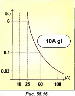
Consider the operating curve of a gl series industrial fuse rated at 10A (see Figure 55.16).
With a current of 10 A passing through this fuse, the latter will never melt (which a priori seems to be normal). If the current reaches 25 A, the fuse will melt after 6 seconds, and at 60 A, after 0.1 seconds.
Such a fuse cannot be used to protect a short circuit of a motor with a rated current of 10 A. In fact, if the starting current reaches 60 A and the duration of the starting period exceeds 0.1 seconds (which happens very often), the fuse will melt on the first attempt to start engine.
Therefore, this series of fuses (gl) can be used to protect against short circuits such consumers, in which the starting current either does not differ at all from the rated current (for example, electric heaters), or the duration of the starting period is extremely short (for example, incandescent lamps, such as those that shown in Fig. 54.39).
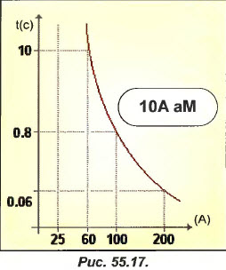
Consider now the curve of an aM series fuse (compatible with the motor), also rated at 10 A (see Fig. 55.17).
It can be seen that the fuse of this series is capable of withstanding a current of 25 A indefinitely without disconnecting the consumer. When a current of 60 A passes through it, it withstands 10 seconds before melting (instead of 0.1 s for the gl series), which is quite enough to start the engine. On the other hand, if a short circuit occurs, it will very quickly disconnect the network from the consumer, limiting the short circuit current to a perfectly acceptable value.
Therefore, this series of fuses (aM) is intended for short-circuit protection of consumers having a long period of inrush current (e.g. electric motors) or characterized by a very high inrush current with a short duration (e.g. primary winding transformer, which is less common).
The selection of fuses (and the electromagnetic circuit breakers that are increasingly replacing them) is a rather complicated and often not fully understood task, although they can be the cause of many anomalies in the operation of the installation. Therefore, the author encourages you to study the numerous technical documentation of various manufacturers of these devices if you wish to increase your knowledge in this area.
"Currently, adjustable motor protection circuit breakers are widely used, which combine the functions of a thermal relay and aM type fuses, which allows, with the correct selection and configuration of the machine, to reliably protect the engine. Therefore, all of the above about thermal relays and aM type fuses can be can also be attributed to adjustable motor protection circuit breakers.However, when choosing a circuit breaker, we recommend that you strictly follow the manufacturer's recommendations.
Main menu
Mains voltage drop
Because of what there is a voltage drop in the mains. So, as you can see from the figures, all networks are sequential. And the farther from the distribution point, the less voltage reaches the consumer. This is done to significantly save cables. All sections are calculated in such a way that the same voltage would come to all consumers. And when the network is new, this is what happens. But over time, the networks wear out, the conductivity of the wires deteriorates, twists appear, and the network is overloaded. And in the end we get a strong voltage drop, this situation is shown in the figures. At the TP, the voltage begins to increase. So that the last consumers get at least something. At the same time, electrical appliances begin to fail at the first consumers due to high voltage. In such situations, only a voltage stabilizer can help. At high voltage it dumps excess into the network, like a reducer. At undervoltage The stabilizer pumps out voltage from the network like a pump. In an old or long electrical network, it is also necessary to install voltage stabilizers for each consumer to equalize the imbalance in the network. But this is already done by consumers themselves.
Why does the voltage drop occur in the mains:
1. Air power networks are laid from aluminum wire without isolation. Over time, aluminum, if a current is passed through it, deteriorates its conductive properties, destroys crystal cell, resistance increases.
2. Local electricians, as a rule, use ordinary twisting rather than bolting when connecting wires, which adds resistance to current.
3. When the network is overloaded. The cross section of the wires limits the current that can be started through them.
Power outages, long-term voltage drops in the power grid or its sudden drops - each of us has repeatedly encountered such phenomena. In addition to the inconvenience and wasted nerves, such situations threaten with breakdowns of electrical appliances, and, accordingly, large unforeseen costs. Why does the voltage drop, how does it manifest itself, and how to avoid its fluctuations? Let's figure it out.
Excessive power load
A significant decrease in the voltage level in the mains is indicated by the dim light of incandescent lamps, interrupted operation or shutdown household appliances and hardware. The main reason for this phenomenon is the aging of power lines.
The fact is that air lines, supplying electricity to private houses and summer cottages, were designed and built quite a long time ago, when the load on one house did not exceed 1-2 kW. However, electrical appliances in a modern house, even a country house, consume several times more, so power lines simply cannot physically provide the required voltage level.
In addition, the wires are exposed external factors- precipitation, a sharp change in temperature, due to which the contacts are broken at the points of their connections and there are losses of electricity. To get rid of voltage fluctuations in a country house and keep electrical appliances safe, they are used, the task of which is to smooth out such drops.
Voltage fluctuations in the mains
The situation is as follows: if the load on the power line is low, the voltage does not go beyond the norm - 210-230V, and when the load begins to grow, the voltage drops to critical 120-130V. power engineers to prevent such a fall, in which electrical devices refuse to work, they supply voltage from the transformer at the level of 250-260V, i.e. with some reserve. As a result (if we are talking about a dacha partnership), on weekends, when the load on the power grid increases, the voltage level drops significantly, and by Sunday evening or Monday it rises sharply to 250V and higher, which quite often leads to breakdowns of household appliances.
The owners of houses located near the substation and, conversely, as far as possible from it, suffer the most. In the former, the tension is almost constantly increased, while in the latter it is lowered, which in both cases does not lead to anything good. That is why experts recommend installing special devices that can maintain the voltage level within acceptable limits. The simplest one at the input of the electrical network completely eliminates the problems caused by power surges and allows homeowners to use any technique absolutely calmly.


