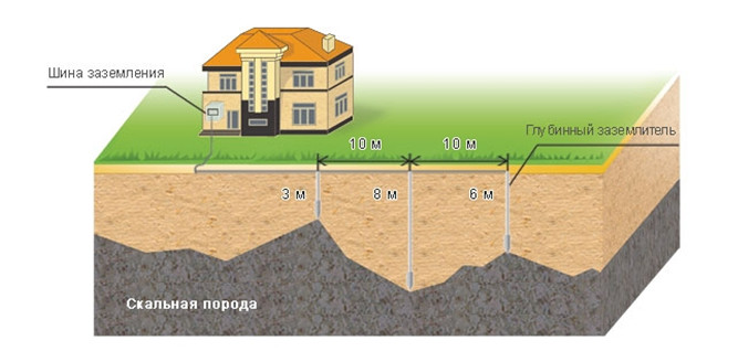
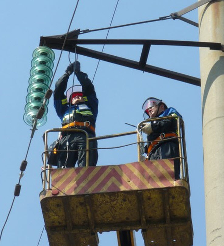
AT modern world It is almost impossible to imagine life without technology that works with electricity. We can say that it has become quite firmly established in the lives of many, and without it it is difficult to imagine a “normal” life. But it happens that the equipment you love and need can suddenly turn into a source of danger to life. It is to avoid such situations that you need to use a ground loop. (Fig. 1)
Almost all modern houses equipped with all kinds of electrical engineering, which is part of our Everyday life. But if the insulation is broken, it can turn from an indispensable assistant into equipment that poses a real threat to life. To prevent it from arising, a ground loop is arranged in the houses.
What is a ground loop for?
Grounding is a device of a special design that will be connected to the ground (ground). In this case, such a connection includes electrical devices, which in their normal state are not energized. But in case of violation of operating conditions or other reasons that led to damage to the insulation, it can occur. Therefore, it is so important to comply with the grounding standards of the ground loop.
The whole point is as follows - the current always tends to where there is the least resistance. So in the event of a violation in the equipment, current flows out to the body of the product. The equipment begins to work intermittently and gradually becomes unusable. But something else is much worse - when you touch such a surface, a person receives such a discharge that he simply dies.
But when using a - ground loop, the following will occur. The voltage will be shared between the existing circuit and the person. That's just the ground loop in this case will have less resistance. And this means that although a person will feel inconvenience, all the same, the entire main current will go through the circuit into the ground.
Important! When arranging a ground loop, it will be important to remember and observe everything necessary for arranging it with minimal resistance.
Ground loop - types and its device
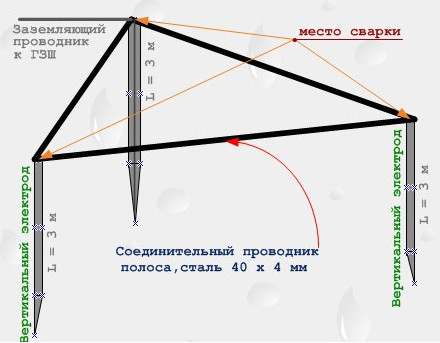
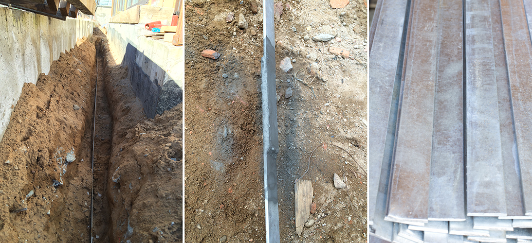
Basically, metal rods are used for grounding, which play the role of electrodes. They are interconnected and deepen a sufficient distance into the ground. This design is connected to the shield installed in the house. For this, a strip of metal of the required thickness is used. (fig.2)
The very distance to which the electrode is immersed directly depends on the height of the location. ground water. The higher their occurrence, the higher the grounding system. But with all this, its removal from the desired object is from one meter to ten meters. This distance is an important condition and must be strictly observed.
Location of electrodes often wear uniform geometric figure. Often it is a triangle, line or square. The shape is affected by the area that must be covered and ease of installation.
Important! The grounding system is necessarily located below the level of soil freezing that exists in a particular place.
The main types of ground loops
So there are two main types of technological solutions. These are ground loops - deep and traditional.
So with the traditional method, the location of the electrodes is as follows - some are located horizontally, and the rest are vertical. The first electrode is a steel strip, and the second are, respectively, metal rods. All of them must have valid values for their size.
It must be borne in mind that the place for the device of the kennel must be selected from the fact that it should be less crowded. The best for this will be the shady side with constant soil moisture.
But this ground loop has its drawbacks:
- rather difficult and physically heavy device;
- the metal products that make up the circuit are subject to corrosion, which not only destroys it, but will burn them to cause a deterioration in conductivity;
- since it is located in the upper part of the earth, it depends very much on the parameters environment which can change its conductive characteristics.
The deep method is much more efficient than the traditional one. It is produced by specialized manufacturers. And it has a number of advantages:
- complies with all established standards;
- service life is significantly longer;
- does not depend on the environment, due to the depth of occurrence;
- installation is quite simple.
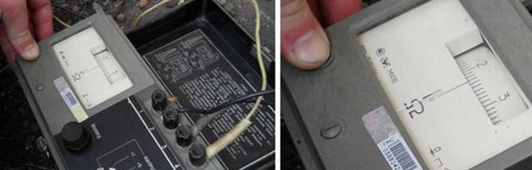
It must be borne in mind that after the device of any type of ground loop, it is necessary to check its compliance with all requirements and reliability. For this purpose it is necessary to invite specialized experts. They must be licensed to carry out such activities. After verification, an appropriate conclusion is issued. It is necessary to bring a passport to the ground loop, attach a test report and a permit for use to it. (Fig. 3)
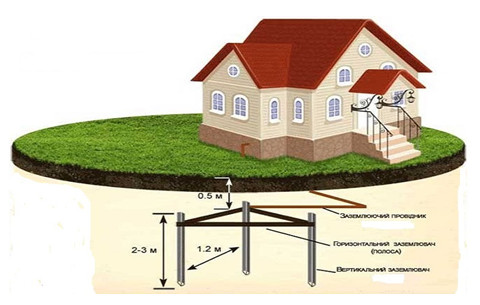
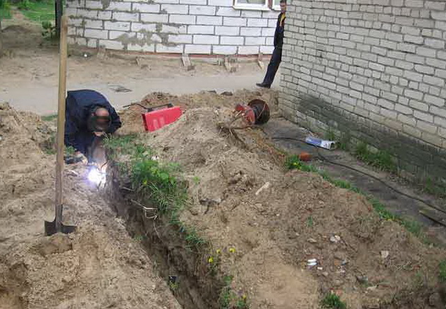
Important! It is impossible to save on materials when constructing a ground loop (Fig. 4). Otherwise, his work will be completely reduced to zero.
External ground loop
This system serves as a transformer substation and is closed. Consists of a small number of electrodes. They are located vertically. Horizontal grounding, it is made, and steel strips 4 * 40 mm.
The ground loop should have a resistance of 40 m, no more, and the earth should be maximum 1000 m / m. Currently, according to the rules, you can increase the values, but not more than ten times for the ground. From this we can conclude that in order to achieve a value of 40 m, it is necessary to vertically install eight electrodes of five meters each. They must be made from a circle with a diameter of 16 mm. Or you can use ten three meters, when using a corner made of steel 50 * 50 mm.
The outer contour is removed from the edge of the building by more than a meter. Elements located horizontally are buried in a trench at a distance of 700 mm from the level of the soil surface. The strip has a rib.
Thus, it is clear that existing norms should be strictly guided. So the ground loop of the PUE is reflected in chapter 1.7. It is also necessary to keep track of all changes in requirements, which can happen quite often.
PTEEP
Chapter 2.7. GROUNDING DEVICES
2.7.1. This chapter applies to all types of grounding devices, potential equalization systems, etc. (hereinafter - grounding devices).
2.7.2. Grounding devices must comply with the requirements of state standards, electrical installation regulations, building codes and regulations and other regulatory and technical documents, ensure the safety of people, operating modes and protection of electrical installations.
2.7.3. The admission to operation of grounding devices is carried out in accordance with established requirements.
When commissioning a grounding device, the installation organization must submit documentation in accordance with the established requirements and rules.
2.7.4. The connection of grounding conductors to the ground electrode and grounding structures must be carried out by welding, and to the main grounding clamp, bodies of apparatuses, machines and supports of overhead lines - by bolting (to enable measurements). Contact connections must meet the requirements of state standards.
2.7.5. Installation of grounding conductors, grounding conductors, connection of grounding conductors to grounding conductors and equipment must comply with the established requirements.
2.7.6. Each part of the electrical installation to be grounded or grounded must be connected to the grounding or grounding network using a separate conductor. serial connection grounding (zeroing) conductors of several elements of the electrical installation is not allowed.
Cross section of grounding and zero protective conductors must comply with the rules for the installation of electrical installations.
2.7.7. Exposed ground conductors must be protected from corrosion and painted black.
2.7.8. To determine the technical condition of the grounding device, visual inspections of the visible part, inspections of the grounding device with selective opening of the soil, measurement of the parameters of the grounding device in accordance with the standards for testing electrical equipment (Appendix 3) should be carried out.
In order for the ground loop to effectively perform its functions, it is necessary to use the standards that are given in the "Electrical Installation Rules". They were approved by the Ministry of Energy of Russia, by order of 08.07.2002. Now the seventh edition is valid. But before implementing a specific project, it is necessary to clarify latest changes. Since further in the article there are links to this document, the following abbreviations will be applied: "PUE", or "Rules".
Typical diagrams of ground loops at home
Why comply with the requirements
It may seem that strict observance of the Rules is redundant, it is necessary only for passing official checks, commissioning a property. Of course it isn't.
The regulations are based on scientific knowledge and practical experience. The PUE contains the following information:
- Formulas for calculating individual parameters of the protective system.
- Tables with coefficients that help to take into account the electrical characteristics of different conductors.
- Procedure for conducting tests and inspections.
- Specialized organizational events.
The application of these standards in practice will prevent the defeat electric shock people and animals. The creation of the contour must be flawless, in strict accordance with the Rules. This will reduce the likelihood of fires in case of accidents, help to eliminate the development of negative processes that can cause damage to property.
This article discusses the protection of a private home. Thus, those sections of the PUE that relate to work with voltages up to 1,000 V will be studied.
Components of the system
The key parameter of this system is the ground resistance. The grounding resistance should be so low that the current would flow along this path in the event of an emergency. This will provide protection if a person accidentally touches the surface to which voltage is applied.

To obtain the desired result, the chassis and housings of household appliances at home are connected to the main bus of the grounding device, an internal circuit is created. Metal elements of the building structure, water pipes are also connected to it. The composition of such a potential equalization system is described in detail in the PUE (clause 1.7.82). Outside the building, another part of the protection, the outer contour, is installed. It is also connected to the main bus. To equip a private house, you can use different schemes. But the easiest way is to bury metal rods into the ground.
The following list shows the individual system components and their requirements:
- The wires that connect the irons, washing machines and other end users. They are inside network cable so it only needs a proper grounding line connected to the outlet. In some situations, when installing hobs, ovens, and other equipment built into furniture, it is necessary to connect the cases with a separate wire.
- As a common bus, you can use not only a special wire, but also "natural" conductors such as metal frames buildings. Exceptions and precise rules will be discussed below. It should also be noted here that this section of the current passage must be created in such a way as to prevent mechanical damage during operation.
- The outer contour of a private house is created from metal elements without insulation. This increases the likelihood of destruction by the corrosion process. To reduce this negative impact non-ferrous metals are used. Places of welded joints of steel parts are coated with bituminous mixtures and other compositions of a similar purpose.
- The actual resistance of this type of grounding device will depend on the characteristics of the soil. Clay and shale retain moisture well, while sand does not. In rocky soils, the resistance is too high, so you will need to look for another place to install, or immerse the ground electrode even deeper. In especially dry periods, regular watering of the soil is recommended to maintain the functionality of the device.

Soils have different conductivity
Earth conductors
Part of the inner contour are insulated wires. Their shells are made colored (alternating green and yellow longitudinal stripes). This solution reduces erroneous actions when performing installation operations. The requirements are detailed in the section "Protective conductors" of the Rules, starting from section 1.7.121.
In particular, there is a method for a simple calculation of the allowable area of an insulated conductor in a section (without a surface layer). If the phase wire is less than or does not exceed 16 mm 2, then equal diameters are chosen. When increasing the size, other proportions are used.
For accurate calculations, the formula from paragraph 1.7.126 of the PUE is used:
/ k, where:
- S - cross section of the ground conductor in mm 2;
- I is the current passing through it during a short circuit;
- t is the time in seconds for which the machine will break the power circuit;
- k is a special complex coefficient.
The magnitude of the current must be sufficient to operate the machine in a time not exceeding five seconds. In order for the system to be calculated with a certain margin, the nearest larger product is selected. The special coefficient is taken from tables 1.7.6., 1.7.7., 1.7.8. and 1.7.9. Rules.
If you plan to use a stranded aluminum cable, in which one of the conductors is protective, then the following coefficients are used, taking into account different insulating sheaths.
Table of coefficients taking into account the type of insulating shells
Structural details can be used as the following elements of the internal contour of a private house. Suitable metal reinforcement, which is located inside reinforced concrete products.
When using this option, the continuity of the circuit is ensured, additional measures are taken to protect against mechanical influences. The features of a particular structure, structural deformations that occur during shrinkage are taken into account.
Not allowed to use:
- Parts of pipeline systems for gas supply, sewerage, heating, gas supply.
- Water supply pipes made of metal, if they are connected using gaskets made of polymers, other dielectric materials.
- Steel strings used to fasten lamps, corrugated sheaths, other insufficiently strong conductors, or products that are under a relatively large load for their parameters.
If a separate copper wire nick that is not part of the power supply cable, or it is not in a common insulating, protective sheath with phase conductors, the following minimum cross section in mm 2 is permissible:
- with additional protection against mechanical influences - 2.5;
- in the absence of such protective means - 4.

This copper conductor is not protected from accidental mechanical damage.
Aluminum is less durable than copper. Therefore, the cross section of a conductor made of such a metal (option - a separate gasket) must be equal to or more than the following norm: 16 mm 2.
What should be the cross section of the conductors of the external ground loop of the house can be seen in the table below.
Cross-section of conductors of the external ground loop
When passing through the outer thick wall of the house, it is easier to drill a thin hole. It can be reinforced from the inside with a tube of suitable dimensions. Copper wire will not be difficult to bend at an angle to attach to the steel bus of the outer circuit.
The permissible resistance of the grounding device is defined in clause 1.7.101 of the PUE. Summary norms are shown in the table below.
Standards of permissible resistance of the grounding device
| When connecting an earth electrode to the neutral of a generator or other source | |||
|---|---|---|---|
| 2 | 4 | 8 | |
| 380 | 220 | 127 | |
| 660 | 380 | 220 | |
| At a close distance from the ground electrode to the current source | |||
| Grounding device resistance, Ohm | 15 | 30 | 60 |
| Voltage (V) in a single-phase current network | 380 | 220 | 127 |
| Voltage (V) in a three-phase current network | 660 | 380 | 220 |
The above standards are valid for cases where the soil resistance (specific) does not exceed the threshold R \u003d 100 Ohm per meter. Otherwise, it is permissible to increase the resistance by multiplying the original value by R * 0.01. The final resistance of the grounding conductor should not be more than 10 times the original value.
Outside the city, overhead power lines are often used to connect the house. Therefore, it is appropriate to mention the rules of the PUE related to the relevant situation. If the conductor simultaneously performs the functions of a protective and neutral (PEN-type), then a re-grounding device is installed at the ends of such lines, consumer connection areas. This is usually the responsibility of the power company, but the owner of the home should check accordingly. As a ground electrode, metal parts of the supports buried in the ground are used.
Overhead power line grounding
When choosing the components of a personal external circuit to be installed in the ground, the following PUE standards are used.
Parameters of the component elements of the external ground loop according to the standards of the PUE
| Profile products in section | Round (for vertical elements systems grounding) | Round (for horizontal elements systems grounding) | Rectangular | Angular | Kol- end (pipe- ny) |
|---|---|---|---|---|---|
| Steel black | |||||
| Diameter, mm | 16 | 10 | 32 | ||
| 100 | 100 | ||||
| Wall thickness, mm | 4 | 4 | 3,5 | ||
| Steel galvanized | |||||
| Diameter, mm | 12 | 10 | 25 | ||
| Cross-sectional area, mm 2 | 75 | ||||
| Wall thickness, mm | 3 | 2 | |||
| Copper | |||||
| Diameter, mm | 12 | 20 | |||
| Cross-sectional area, mm 2 | 50 | ||||
| Wall thickness, mm | 2 | 2 | |||
If the risk of damage to horizontal sections by oxidative processes is increased, the following solutions are applied:
- Increase the cross-sectional area of the conductors above the norm specified in the PUE.
- Products with a galvanized surface layer or made of copper are used.
Trenches with horizontal grounding are covered with soil with a homogeneous structure, without debris. Excessive drying of the soil can increase resistance, therefore, in the summer, when there is no rain for a long time, the corresponding areas are specially watered.
When laying the ground loop, avoid proximity to pipelines that artificially increase the temperature of the soil.
What should be the resistance
The strength of metal conductors, their electrical resistance is easy to determine. If there should be some resistance to the PUE, then compliance with the rules will not be overly difficult. So, for example, for grounding supports overhead lines the maximum allowable standard is 10 Ohm, if the equivalent soil resistance does not exceed 100 Ohm * m (Table 2.5.19.). The integrity of welded joints is ensured additional protection anti-corrosion layer. If there is a risk of rupture in the process of soil shifts, or deformation of the structure, the corresponding section is made of a flexible cable.
But much more problems arise with the land. In this inhomogeneous medium, subject to a variety of external influences, the same conductivity value for a long time is impossible. That is why in the PUE a separate section is devoted to grounding devices that are installed in soils with high resistivity (standards according to paragraphs 1.7.105. - 1.7.108.).
- Metal elements (ground electrodes of vertical type) of increased length are used. In particular, it is permissible to connect to pipes installed in artesian wells.
- Grounding switches are transferred to a great distance from the house (no more than 2000 m), to where the soil resistance (Ohm) is less.
- In rocky and other "complex" rocks, trenches are laid into which clay or other suitable soil is poured. There, in turn, elements of a horizontal type grounding system are installed.
Horizontal earthing switches in the earthing system
If the resistivity of the soil exceeds 500 ohms per m, and the creation of a grounding conductor is associated with excessive costs, it is allowed to exceed the norm of grounding devices by no more than 10 times. The following formula is used for the calculation. The exact value should be: R * 0.002. Here, the value of R is the specific equivalent soil resistance, in ohms per m.
Inner and outer contour
As a rule, the main bus inside the building is installed inside the input device. It can only be made of steel or copper. The use of aluminum in this case is not allowed. Measures are taken to prevent free access to it by unauthorized people. The tire is placed in a locker, or in a separate room.
Connect to it:
- metal elements of the building structure;
- conductor of the external ground loop;
- conductors PE and PEN types;
- metal pipelines and conductive parts of water supply, air conditioning and ventilation systems.
The external contour of the house is created, taking into account the PUE standards listed above for individual parts of the system. This will allow you to obtain the required minimum resistance of the grounding system (Ohm), which is sufficient for reliable protection. For re-grounding, it is recommended to use natural type grounding conductors.
The resistance (Ohm) of the repeated ground electrode is not clearly defined by the provisions of the PUE.
Below are some important features of a standard private house ground electrode:
- The main part, vertical elements, are installed at a small distance from the house, taking into account soil parameters.
- To them, a trench is laid with a depth of up to 0.8 m and at least 0.4 m wide, in which horizontal sections of the chain are installed. There is no exact norm, but the dimensions of the trench must be sufficient for the unhindered installation of elements.
- Vertical earthing switches up to 3 m long are installed in the corners of an equilateral (3 m each) triangle. These dimensions are given as an example. There are no exact length standards. There are norms only for the maximum allowable resistance of the protective system.
- To make it easier to drive them into the ground, the ends are sharpened.
- Strips are attached to the protruding parts by a welded joint.
- The trenches are covered with soil that is uniform in structure and does not contain crushed stone.
Installation of an external ground loop of a private house
If bolted connections are used in the grounding circuit, measures are taken against their unwinding. As a rule, the corresponding nodes are welded.
Video. DIY grounding
The standards for test procedures are set out in chapter 1.8 of the PUE, as well as in the "Rules technical operation electrical installations of consumers” (PTEEP, pr. 3.1), effective from July 1, 2003 on the basis of a decision of the Russian Ministry of Energy (order dated January 13, 2003). Visual control is carried out, the integrity of the connections is checked. According to a special technique, the resistance of the grounding system loop is determined. The measured value should not be higher than normal (Ohm). If this condition is not met, use a longer ground electrode or other technologies given in this article.
Grounding or grounding should be carried out in all electrical installations alternating current with voltage from 380 V and in electrical installations direct current with voltage from 440 V. In rooms with heightened danger and especially dangerous, as well as in outdoor electrical installations, grounding and grounding are carried out both in AC devices with voltages above 42 V and in DC devices with voltages above 110 V, and in explosive installations - at any AC and DC voltage.
At voltages up to 1000 V in electrical installations with a solidly grounded neutral, zeroing must be performed. In these cases, grounding of cases of electrical receivers without grounding is prohibited.
Artificial ground electrodes should not be colored.
Earthing conductors should not be located (used) in places where the earth dries out under the influence of heat from pipelines, etc.
The trenches for horizontal grounding conductors must be filled with homogeneous soil that does not contain crushed stone and construction debris.
Grounding and zero protective conductors must be protected from corrosion.
The use of bare aluminum conductors for laying in the ground as grounding or zero protective conductors is not allowed.
There are certain requirements for grounding and grounding of electrical receivers of various types.
1. Each grounded part of the electrical installation must be connected to the grounding line by a separate branch. Serial connection to the ground conductor of several parts is prohibited.
2. Cross-sections of copper and aluminum conductors for grounding of various parts of the electrical installation must correspond to the values indicated.
3. Grounding branches to single-phase electrical receivers must be carried out by a separate (third) conductor; it is forbidden to use a neutral working wire for this purpose.
4. Connection of grounding branches to metal structures should be carried out by welding, and to the bodies of apparatuses and machines - by bolts. The contact surfaces must be cleaned to a metallic sheen and lubricated with a thin layer of Vaseline.
5. Metal cases of mobile and portable electrical receivers are grounded with a special residential flexible wire, which should not simultaneously serve as a conductor of the working current. It is forbidden to use the zero working wire of the electrical installation for this purpose.
6. Connecting the grounding conductor to the grounding or neutral contact of the socket should be carried out with a separate conductor. The plug for turning on a portable electrical receiver must have an elongated grounding pin that comes into contact with the grounding contact of the outlet before the current-carrying contacts are connected.
7. The cores of wires and cables for grounding portable and mobile installations must have cross sections equal to the cross sections of the phase wires and be in a common sheath with them.
3. Is it possible to crimp a copper wire with aluminum in a copper sleeve?
copper and aluminum wires it is not recommended to connect, because the difference between the electrochemical potentials of aluminum and copper is too great. As a result, a galvanic pair (such as a battery) is formed. This leads to an increase in the transition resistance of the contact, it begins to heat up and spark, and electroerosive destruction is added.
It is possible to pressurize if the sleeve is tinned and tightly clamped with tongs.
Introduction
Description, characteristics of the enterprise
a brief description of workshops
Characteristics of the work performed
Grounding and grounding of electrical equipment. Zeroing executions. Device mounting protective earth
2 External ground loop and its installation
3 Measuring the resistance of earthing devices
4 Installation of the internal grounding network
5 PUE requirements for grounding electrical installations
Safety
1 Organization of the electrician's workplace
2 Safety requirements before starting work
3 Safety requirements during work
4 Safety requirements in emergency situations
5 Safety requirements at the end of work
Bibliography
Introduction
The electrical industry plays an important role in solving the problems of electrification, technical re-equipment of all branches of the national economy, mechanization, automation and identification of production processes.
The volume of electricity production in Russia by 2005 exceeds 1 trillion. kV/h Installed electric power individual enterprises reaches 3 million kW, and the number electrical machines on them - 100 thousand pieces. annual electricity consumption at a number of enterprises already today exceeds 5 billion kW/h. For every 10 years, the production and consumption of electricity in the world approximately doubles. The growth of labor productivity, the development of electrically intensive electrical processes, the implementation of environmental protection measures, the introduction of advanced technologies will lead in the period 1999-2010. to a further increase in the electric power of enterprises.
An important role in the development of domestic electrical engineering was played by the works of Russian scientists and inventors P.N. Yablochkova, A.N. Lodygina, M.O. Dolivo-Dobrovolsky and others. The priority in the creation and application of a three-phase AC system belongs to M.O. Dolivo-Dobrovolsky, who in 1891 carried out the transfer electrical energy with a power of about 150 kW at a voltage of 15 kV at a distance of 175 km. They also created synchronous generator, three-phase transformer and asynchronous motor.
In 1920, the All-Russian Congress of Soviets approved the State Plan for the Electrification of Russia (GOELRO), which provided for the construction of thirty new regional power plants with an energy production of up to 8.8 billion kWh per year within 10-15 years. This plan was completed in 10 years. Since 1930, large urban district thermal power plants have been gradually integrated into electrical systems, which to this day remain the main producers of electricity for the vast majority of enterprises.
Until 1960, the capacity of large generators of thermal power plants was 100 MW. Six to eight generators were installed at one power plant. Therefore, the capacity of large thermal power plants was 600-800 MW. After the development of blocks of 150-200 MW, the capacity of large power plants increased to 1200 MW, and after the development of blocks of 300 MW - to 2400 MW. Currently, thermal power plants with a capacity of 6000 MW with units of 500-800 MW are being introduced.
Efficiency of interconnection of power systems by saving the total installed capacity of generators due to the combination of load peaks of power systems shifted in time.
During the period of market reforms in Russia, the electric power industry, as before, is the most important life-supporting industry of the country. It includes over 700 power plants with a total capacity of 215.6 million kW.
The Unified Energy System of Russia is one of the world's largest highly automated electric power complexes that provides the production, transmission and distribution of electricity and centralized operational dispatch control of these processes. As part of the UES of Russia, about 450 large power plants of various departmental affiliations operate in parallel, with a total capacity of more than 200 million kW, and there are also over 2.5 million km of power transmission lines of various voltages, including 30 thousand km of backbone transmission lines with a voltage of 500, 750, 1150 kV.
Maintenance of electrical installations of industrial enterprises is carried out by hundreds of thousands of electricians, on whose qualifications the reliable and uninterrupted operation of electrical installations largely depends. The personnel must know the basic requirements of the Rules for the technical operation of electrical installations of consumers, GOSTs and other directive materials, as well as the design of electrical machines, transformers and devices, skillfully use the materials, tools, fixtures and equipment used in the operation of electrical installations.
1. Description, characteristics of the enterprise
"Omskshina" plant is one of the leading enterprises chemical industry Omsk region. The plant became part of the SIBUR holding - Russian Tires on January 1, 2006, which also includes almost all Russian tire industry enterprises. The finished products of the plant are automobile and aircraft tires of various assortments.
The company is located near the city center in industrial area of the city at 2 Buderkina Street. In fact, the main construction of the plant began in the autumn of 1941. The Yaroslavl and Leningrad tire plants were evacuated to Omsk. On February 24, 1942, the first tire in size 6.50-20 (for a lorry) rolled off the assembly line of the plant. This day is considered to be the birthday of the Omsk Tire Plant. In 1944, the plant was twice awarded the Red Banner of the USSR State Defense Committee.
Today, Omskshina is the second largest tire manufacturer in Russia. Three stages can be clearly traced in the history of the Omsk tire industry:
From 1942 to 1964 - the period of formation and development in the war and post-war years;
From 1964 to 1993 - the time of expansion of production, achievement of high economic indicators and development of the social sphere, ending with a period of decline in production;
From 1993 to the present - a period of privatization and restructuring of production, gaining new market positions.
2. Brief description of the workshop
The finished products of the autotube workshop are various types of autotubes, as well as commercial rubber.
The equipment with which the autochamber shop is equipped and its quantity is presented in table 1.
Table 1. - List of equipment installed in the autocamera
Item No. Name of equipment Quantity 1 RS 270 rubber mixer ×30 32Rubber mixer RS 270 ×40 33 -grain of MCH 380/450 34 Drum Drum for granules 35valists individual SM 2100 660/66046 VALIARY DEMIRED SM 2130 660/66027 VALIALYS PD 800 550/55018 VALSTS INSTALLY PD 630 315/31519 Simplifier 60/160110 SimbaM/PECTIONAL DR 800/611111111111111111111111111111111111111111111111AROTHS IN 660312Турбовоздуходувка ТВ - 80 - 1,6813Агрегат измельчения резиновых отходов АПР 420/400114Машина одночервячная МЧТ - 250 315Машина одночервячная МЧТ - 200116Агрегат камерный317Агрегат флепповый118Станок стыковочный для ездовых камер ВМИ ЕПЕ1319Станок стыковочный для ездовых камер МИНЛАНД520Станок стыковочный для ездовых камер РОССИЯ221Индивидуальный вулканизатор камер ИВК - 458122Индивидуальный вулканизатор камер ИВК - 552723Individual vulcanizer of IVK chambers - 75924Individual vulcanizer of IVK chambers - 85225Vulcanizer of rim tapes VOL4926Hydraulic vulcanization press1427Buffing machine 828Valve bending machine929Chamber sleeve trimming machine230Stan ok for punching holes in flepps431Machine for punching valve heels132Device for screwing spools433Pneumatic knife for cutting rubber334Installation for checking auto-chambers for tightness2 3. Characteristics of the work performed
During my internship, I worked various works related directly to my specialty - electrician. Each working day began with a tour of the equipment and inspection of electrical installations. Also, in turn, the means were checked personal protection: mats, boots, gloves. After inspecting the equipment, an entry was made in the "Shift (operational) journal for duty personnel to record work Maintenance and repair of electrical equipment. The list of work, the assignment for the shift was also recorded in the journal. In addition to a certain task, I had to perform troubleshooting work that interfered with the productivity of the main production, i.e. replacement of a burned-out light bulb above the vulcanizer of the chambers or replacement of a burned-out engine on the punch of the second syringe of the machine. Shutdown and start-up of equipment (after a holiday) is logged. I had to engage in locksmith work, the manufacture of fasteners for temporary wiring. I also had to perform rigging work not directly related to installation or maintenance, to take away the burned-out electric motor for rewinding. Maintenance was carried out at transformer substation No. 26, maintenance of electrical machines (electric motor), as well as on a 10 kW switchgear. Maintenance consisted of cleaning the installation from dirt and dust, drawing bolted connections. 4. Grounding and grounding of electrical equipment. Versions zeroing. Installation of protective earthing devices
.1 General
If the insulation of electrical equipment is damaged, its various metal non-current-carrying parts may accidentally become energized, creating a danger of electric shock to a person. Touching equipment with damaged insulation, a person becomes a conductor for current to the ground. Currents from 0.05 A are dangerous for humans, and currents of 0.1 A are deadly. The value of the current passing into the ground depends on the electrical resistance of the human body and the voltage of the damaged installation. The resistance of the human body varies widely: from several hundred to thousands of ohms, therefore, installations with relatively small voltage in relation to the earth. The voltage relative to the ground in case of a short circuit to the case is the voltage between this case and ground points that are outside the zone of current spreading in the ground, but not closer than 20 meters from this zone. One of the main measures to protect people from electric shock when touching installations that accidentally become energized is a protective earthing device. Grounding is intentional electrical connection any part of the installation with earth, performed using earthing switches and earthing conductors. A grounding conductor is a metal conductor or a group of conductors embedded in the ground. A grounding conductor is a metal conductor connecting the grounded parts of an electrical installation with grounding conductors. A grounding device is a combination of grounding conductors and grounding conductors. The safety of people is achieved only if the grounding device will have many times less resistance than the lowest resistance of the human body. The resistance of the grounding device is the sum of the resistances of the grounding conductor relative to the earth and the grounding conductors, and it must be within the limits determined by the preliminary calculation. The maximum allowable resistance of grounding devices is determined by the voltage of the installation, the values of earth fault currents, the presence of a neutral and some other conditions and are established by the current PUE (rules for electrical installations). Earth fault current - the current passing through the earth at the location of the fault. To protect people from electric shock in case of damage to the insulation, metal non-current-carrying parts of electrical equipment are grounded. A set of measures and technical devices designed for this purpose is called protective grounding. Protective grounding is a deliberate connection to the ground under the means of grounding conductors and grounding conductors of non-current-carrying metal parts of electrical installations (disconnector drive handles, transformer casings, flanges of support insulators, housings transformer substations etc.). The task of protective grounding is to create a sufficiently low resistance between metal structures or the body of the protected device and the ground; in case of single-phase short circuits to the ground or to the case of conductive damaged parts of electrical installations, such a connection provides a decrease in current to a value that does not threaten human life and health, since the electrical resistance of his body is many times higher than the resistance metal conductor connected to earth. An earth fault is an accidental electrical connection of energized parts of an electrical installation directly to the earth or to its structural parts, not isolated from the earth. Protective grounding is accepted in all networks with an isolated neutral and in networks with voltages above 1000 V with a grounded neutral. In the latter, single-phase fault points flow through the ground and cause the emergency section to shut down. Figure 1. Scheme three-phase network with isolated neutral (a) and modes of its operation when a person touches a linear wire (b); grounding of one line wire and a person touching to another (in); touching a person on a line wire in a system with grounded neutral (g) and in a system with grounded neutral and other line wires (d) In a network with a solidly grounded neutral, power receivers are powered by the windings of the current source, connected to a star, the zero point of which is reliably connected to the ground. A dead-earthed neutral is a transformer or generator neutral connected to a grounding device directly or through low resistance. Neutral grounding. The PUE states that urban Electricity of the net above 1000 V should be three-phase with an isolated neutral, and distribution networks in new cities should be three-phase four-wire with a tightly grounded neutral at a voltage of 380/220 V. However, networks with a voltage of 220/127 V with an isolated neutral are also common, in which blowdown fuses are used. windings power transformers of domestic production with a voltage of 110 kV and above are also designed to work with a grounded neutral, since they have incomplete insulation of zero terminals. On fig. 1 shown secondary windings transformer Tr, supplying a four-wire network with a voltage of 380/220 V, the neutral of which is isolated. Let the insulation be perfectly serviceable at the moment under consideration. Nevertheless, the three resistances R, connected in a star, the neutral of which is the earth, conditionally show the imperfection of the insulation of the wires, which to some extent still conducts current. Three capacitors C, connected in a star, the neutral of which is also the earth, are conventionally depicted electrical capacitance wires relative to the ground, which is very important in AC electrical installations, since the capacitance conducts alternating current. What voltages operate in the considered electrical installation? The voltage between the linear wires is 380 V, and between each linear wire and the neutral of the transformer - 220 V, since the earth turned out to be the neutral of the star connections of three equal resistances R and three equal capacitances C. If the linear wire relative to the neutral of the transformer has the same voltage as and relative to earth, then the voltage between the neutral of the transformer and earth is zero, but, of course, only if the network is not loaded or the load of all phases is the same. Figure 2. − Operation of a three-phase network with a solidly grounded neutral when a person touches a conductive wire (a), grounding (b) and grounding (c) of the electric motor Touching a person standing on the ground to one of the line wires is unsafe, since current will pass through the imperfect insulation of the wire and the human body (Fig. 2). The strength of this current, and therefore the degree of danger, is determined by the values of resistances, capacitances of capacitors and phase voltage. In this case, the person is under voltage of 220 V. But what happens if one of the line wires is grounded and a person standing on the ground touches the other line wire? From fig. 3 it is clear that the person will now be not under phase, but under line voltage 380 V, which is much more dangerous. In networks with grounded neutral, a person standing on the ground and touching the line wire falls under phase voltage. If at the same time another linear wire is grounded, the fuse will blow, but the voltage will not increase from phase to linear. Touching a conductive element in a network with a solidly grounded neutral is very dangerous, since this forms a closed circuit, through which, under the influence of voltage from phase A, a striking current flows through the human body, shoes, floor, ground and neutral ground. It is also dangerous to touch the electrical receiver, in which a short circuit to a grounded case has occurred. In addition to ensuring the minimum resistance of the grounding device, it is also important to ensure uniform distribution of voltage around the protected device and over the entire area of the electrical installation. Maximum potential (U 3) have a grounding conductor connected to the body of the damaged apparatus, and soil in contact with the grounding conductor. As you move away from the ground electrode, the potential on the earth's surface drops, gradually reaching zero. The soil resistance at this distance is called spreading resistance. A person touching the body of the device with damaged insulation is under voltage, the value of which is determined by the potential drop in the area between the point of contact with the device and the point where the feet touch the ground. This voltage is called the touch voltage (U prik ). There will also be a potential difference between the feet of a person approaching a damaged apparatus, called the step voltage (U step ), the value of which depends on the step width and the distance to the damage site. Figure 3. Scheme of the occurrence of step voltage Step and touch voltages occur when a single-phase earth fault occurs in a grounded network. Let a single-phase fault current flow to the ground through a vertical grounding switch Z (Fig. 3.), located at point 0. As you move away from the ground electrode, the current density and the voltage drop caused by it continuously decrease, i.e. if the maximum potential is at point 0, then the potential at the point of the ground, located further than 20 m from the ground electrode, is practically equal to zero. The change in the soil potential depending on the distance from point 0 is characterized by the AM curve. By dividing the distance 0M into segments 0.8 m long (the average width of a person's step), it is easy to find out from this curve what voltage a person who is at a certain distance from the ground electrode is under. For example, if the legs of a walking person are at a distance of 1.6 and 2.4 m from the earth electrode, then the ground potentials are characterized by points C and D of the AM curve, and the VZ segment on a certain scale determines the potential difference, i.e. voltage. The voltage under which a person may be walking in the area of \u200b\u200bspreading a single-phase short circuit current on the ground is called the step voltage. This voltage decreases with distance from the ground electrode (VZh<БЕ<АД) и на расстоянии более 20 м от заземлителя оно практически исчезает. Personal injury due to the appearance of a step voltage in the case of a single-phase earth fault is very rare due to the low values of this voltage. But if this voltage occurs when a broken wire of an overhead line falls to the ground, it can reach large values. In such cases, one should leave the zone of action of the step voltage using dry boards, plastic sheets and other insulating materials, and in their absence, in small steps. Also dangerous is the voltage that has arisen during the operation of protective grounding in the single-phase ground fault mode. If current I flows through the grounding conductor to the ground 3, then the resistance of the grounding device R 3it creates voltage drops I 3R 3, i.e. touch voltage. In this case, touching the body of the device with damaged insulation, a person can either get under full voltage I 3R 3, or under part of it. The most dangerous cases are when the receiver with damaged insulation and the person who touched it are at distances of more than 20 m from the ground electrode, and if the person is standing directly on the ground in damp shoes lined with nails. 4.2 External ground loop and its installation
To ensure the safety of people, protective grounding of electrical installations is carried out. Grounding is subject to: metal casings and cases of electrical installations, various units and drives for them, lamps, metal frames of switchboards, control panels, shields and cabinets; metal structures and metal cases of cable joints, metal sheaths of cables and wires, steel pipes for electrical wiring; secondary windings of measuring transformers. Grounding is not subject to: fittings of suspension and pins of support insulators, equipment installed on grounded metal structures, since their supporting surfaces must be provided with cleaned unpainted places to ensure electrical contact; cases of electrical measuring instruments and relays installed on shields, shields, cabinets, as well as on the walls of switchgear chambers; metal sheaths of control cables in cases that are specifically specified in the project. Protective grounding consists of an external device, which is artificial or natural grounding conductors laid in the ground and interconnected into a common circuit, and an internal network consisting of grounding conductors laid along the walls of the room in which the installation is located and connected to the external circuit. Metal ground electrodes embedded in the ground, having a large area of contact with the ground, provide a low electrical resistance of the circuit. To ground electrical installations, first of all, natural grounding conductors should be used - metal pipelines laid in the ground (except for pipelines with combustible, flammable and explosive liquids or gases); casing; metal and reinforced concrete structures of buildings and structures, securely connected to the ground; lead sheaths of cables laid in the ground, and zero working wires with repeated grounding conductors of overhead lines with voltage up to 1000 V. Natural grounding conductors must be connected to the grounding line of the electrical installation in at least two places. The connection of the grounding conductors to the grounding conductors, as well as the connection of the grounding conductors to each other, is carried out by welding, and the length of the overlap must be equal to twice the width of the conductor with a rectangular section and six diameters - with a round one. With a T-shaped overlap of two strips, the length of the overlap is determined by their width. The connection of grounding conductors to pipelines is carried out by welding (Fig. 4.) or, if this is not possible, by clamps from the side of pipeline entry into the building. Welding seams located in the ground, after installation, are covered with bitumen to protect against corrosion. Figure 4. - Connection to the pipeline by welding the grounding conductor with a rectangular (a) and round (b) section and a clamp If there are no natural grounding conductors or they do not meet the design requirements, an external grounding loop is mounted from artificial grounding conductors, which can be vertical, horizontal and in-depth. Vertical grounding conductors are steel pipes or angle steel driven into the ground, as well as steel rods screwed into the ground. Steel strips laid in the ground with a thickness of at least 4 mm or round steel with a diameter of at least 10 mm are horizontal artificial grounding conductors that play the role of independent grounding elements or serve to connect vertical grounding conductors with each other. A variety of horizontal grounding conductors are recessed grounding conductors laid at the bottom of pits during the construction of foundations for overhead line supports and buildings under construction. They are made in the workshops of the assembly organization after preliminary measurement from strip steel with a cross section of 30 ×4 mm or circular steel with a diameter of 12 mm. The shape of the grounding conductors, their number, section and placement is determined by the project. As grounding conductors can be used: natural conductors, i.e. metal structures of buildings; metal structures for industrial purposes (crane tracks, switchgear frames, galleries, platforms, elevator shafts, lifts); steel pipes for electrical wiring; metal sheaths of cables (but not armor). For zeroing, in all cases, the aluminum sheath of the cables is sufficient, and lead, as a rule, is not enough. In hazardous areas, specially laid grounding conductors are used, and natural ones are considered as an additional measure of protection. When the neutral is grounded (networks 380/220 or 220/127 V), the grounding of electrical receivers of explosive installations must be carried out separately by dedicated conductors of wiring and cables; with an isolated neutral, steel conductors can be used for grounding. The use of bare aluminum conductors as grounding conductors is prohibited due to their rapid destruction due to corrosion. The installation of the external ground loop and the laying of the internal ground network are carried out according to the working drawings of the electrical installation project. Punch work, installation of embedded parts, preparation of free holes, furrows and other openings, laying passageways in walls and foundations, digging earthen trenches for laying an external ground loop is carried out at the first stage of preparation for elementary work. The external ground loop is laid in earthen trenches with a depth of 0.7 m. Artificial ground electrodes in the form of segments of steel pipes, round rods and angles 3 ... earth. Recessed grounding conductors are connected to each other with steel strips with a cross section of 40 ×4 mm by welding. The places where the strip is welded to the ground electrodes are covered with heated bitumen to protect against corrosion. Grounding conductors and grounding conductors located in the ground should not be painted. Trenches with grounding conductors and grounding conductors laid in them are covered with earth that does not contain stones and construction debris. Natural grounding conductors are connected to the grounding lines of the electrical installation by at least two conductors connected in different places. The connection of grounding conductors with extended grounding conductors (pipelines) is carried out near their inputs into buildings using welding or clamps, the contact surface of which is serviced. The pipes in the places where the clamps are laid are cleaned. Places and methods of connection of current receivers are selected in such a way that when the pipeline is disconnected for repair work, the grounding device is continuously operated. Water meters and valves are equipped with bypass connections. The internal grounding network is carried out by open laying indoors along the building surfaces of bare steel conductors with rectangular and round sections. Figure 5 shows examples of laying, fixing and connecting PE conductors. Figure 5. - Options for laying (a) and fixing flat and round tires with clips (b), electric welding (c) and built-in dowels (d), overlap welding (d) and welding to the electrode (e) Openly laid bare earth conductors are located vertically, horizontally or parallel to sloping building structures. Conductors with a rectangular cross section are installed with a large plane to the surface of the base. On rectangular sections of the gasket, the conductors should not have irregularities and bends that are noticeable to the eye. Grounding conductors laid on concrete or brick in dry rooms that do not contain caustic vapors and gases are fixed directly on the walls, and in damp, especially damp rooms with caustic vapors and gases - on supports at a distance of at least 10 mm from the wall surfaces. In the channels, grounding conductors are located at a distance of at least 50 mm from the lower surface of the removable floor. The distance between supports for fixing grounding conductors on straight sections is 600…1000 mm. Grounding conductors in places where they cross with cables and pipelines, as well as in other places where mechanical damage is possible, are protected by pipes or other means. In the premises, grounding conductors must be available for inspection, but this requirement does not apply to neutral conductors and metal sheaths of cables, hidden wiring pipelines and metal structures located in the ground. Through the walls, grounding conductors are laid in open openings, pipes or other rigid frames. Each grounded element of the electrical installation must be connected to the grounding line using a separate branch. Serial connection to the grounding conductor of several grounded elements is prohibited. Neutrals of transformers, grounded tightly or through devices that compensate for capacitive current, are connected to the ground electrode system or to prefabricated grounding buses using separate grounding conductors. The grounded terminals of the secondary windings of instrument transformers are connected to their casings with grounding bolts. Flexible jumpers that serve to ground metal sheaths and cable armor are attached to them with a wire bandage and soldered, and then connected by bolted contacts to the cable termination (sleeve) and the grounding structure. The cross section of flexible jumpers must correspond to the cross sections of the grounding conductors adopted for this electrical installation. The points of connection of the grounding jumper with the aluminum sheath of the cable are covered with asphalt varnish or hot bitumen after soldering. The connection of grounding conductors with each other and their connection to the installation structures is carried out by welding, and the connection to the bodies of apparatus and machines is carried out by welding or a reliable bolted connection. Locknuts, spring washers, etc. are installed to prevent loosening of contact during shocks and vibrations. Contact surfaces on grounded electrical equipment at the points of connection of grounding conductors, as well as contact surfaces between grounded equipment and the structures on which it is installed, must be cleaned to a metallic sheen and covered with a thin layer of petroleum jelly. 4.3 Measuring the resistance of earthing devices protective earth electrical equipment resistance Grounding reliably performs its protective functions only if its resistance is sufficiently small. For example, in networks with a dead-earthed neutral, a large resistance of the grounding device can lead to the fact that the strength of the current that has arisen during insulation breakdowns is insufficient to trigger the tripping protective equipment. Therefore, PUE strictly limit the resistance of grounding devices. When grounding electrical installations with voltages up to 1000 V with a solidly grounded neutral, it is necessary to securely connect the neutrals of their power sources (generators, transformers) to the ground electrode, which should be located in close proximity to them. If the transformer substation is located inside the workshop, it is allowed to take out the ground electrodes on the outer side of the building wall. The resistance of the grounding device to which the neutrals of generators and transformers are connected must be no more than 4 ohms, but if their power is 100 kVA and lower, then the resistance, then the resistance of the grounding device should not exceed 10 ohms; during parallel operation of power supplies, the grounding resistance can reach 10 Ohm only if their total power does not exceed 100 kV * A. Figure 6. - Electrical measuring device: Cylinder; aluminum frame; Arrow; Scale After the completion of all installation work, it is mandatory to measure whether the grounding resistance meets the requirements of the PUE. Most often, measurements are made using an ammeter and a voltmeter or an MS-08 device. Electrical measuring instruments - ammeters and voltmeters, which use the orientation effect of a magnetic field on a current-carrying circuit, are arranged as follows. Rice. 6 on a light aluminum frame 2 of a rectangular shape with an arrow 4 attached to it, a coil is wound. The frame is reinforced on two semiaxes OO`. It is held in the equilibrium position by two thin spiral springs 3, the moment of elastic forces of which is proportional to the angle of deflection of the arrow. The coil is placed between the poles of a permanent magnet with specially shaped tips. Inside it is a cylinder 1 made of soft iron. This design provides a radial direction of the magnetic induction line in the area where the turns of the coil are located (Fig. 7, i.e. at any position of the coil, the moment of the forces of the magnetic field is maximum and at a constant current strength is the same. The vectors F and -F correspond to the forces of the magnetic field that act on the coil and create a torque. The current-carrying coil rotates until the moment of elastic forces of the spring balances the moment of forces of the magnetic field. When the current strength is doubled, the arrow also rotates through an angle twice as large, since the maximum moment of the forces M of the magnetic field is directly proportional to the current strength: M~I. Having established which angle of rotation of the arrow corresponds to the known value of the current strength and calibrating the electromagnetic device, it can be used to measure in DC and AC circuits. Ammeters and voltmeters are the most common switchboard instruments due to the simplicity of the device and relatively good overload tolerance. The disadvantages of these devices are low accuracy, high power consumption (up to 10 W), limited frequency range, and sensitivity to external magnetic fields. Figure 7. Scheme of the action of forces in an electrical measuring device Figure 8. - Scheme for measuring ground resistance using ammeter and voltmeter Panel ammeters produce class 1.0; 1.5; 2.5 for currents up to 300 A with direct connection and up to 15 A with external current transformers. Panel voltmeters of the same accuracy classes are available for voltages up to 600 V with direct connection and up to 750 kV with voltage transformers. With direct connection of measuring devices fig. 8 between the ground electrode (G), the resistance of which relative to the ground must be measured, the auxiliary current electrode (T) passes a single-phase alternating current Ix and measures it with an ammeter, and, having immersed the auxiliary potential rod (P) in the ground between the electrodes Z and T, measure the voltage with a voltmeter Ux between it and ground electrode Z. Grounding resistance measurements using an ammeter, voltmeter and transformer are performed in the following order. Electrodes P and T are hammered into the ground (steel rods pointed at the ends about 1 m long). an ammeter and a voltmeter are connected with separate wires to the ground electrode and these electrodes. A voltmeter checks the absence of voltage between the ground electrode and the P rod. If the device shows any voltage, changing the direction of the spacing of the rods or proportionally increasing the distance between them, they achieve its zero value. After that, a rheostat with resistance R is fully introduced and the transformer Tr is connected to the network. With the help of a rheostat, the current strength is gradually increased and the readings of the ammeter and voltmeter are monitored (a simultaneous report on the instruments is made at the moment when their readings can be recorded with the greatest accuracy). According to the measurement data, the resistance of the ground electrode is calculated using Ohm's law: R 3= U x /I x .
At least three measurements are made and the arithmetic mean of the obtained values is taken for calculation. The advantage of such a measurement is the accuracy and the possibility of determining small, very small resistances (up to hundredths of an ohm); the disadvantages are the need for two measuring instruments and a transformer, the influence of mains voltage fluctuations on the measurement accuracy, the lack of a direct report and increased danger to people making measurements. This method is mainly used to measure the resistance of earthing conductors of power plants and large district transformer substations. Grounding resistance can also be measured with the MS-08 instrument (Fig. 9), which has three scales (10 ... 1000, 1 ... 100 and 0.1 ... 10 Ohm), whose operation is based on the principle of simultaneous measurement of current and voltage with a magnetoelectric logometer. Figure 9. - Simplified diagram of the MS-08 device: Ratiometer; Generator; Current interrupter; Rectifier A logometer is an indicating device that measures the ratio of two electrical quantities, in most cases the ratio of two currents. It is used to measure electrical and non-electrical quantities that are independent of current (resistance, phase shift, frequency, temperature, pressure, displacement in space). The deviation of the pointer of most measuring mechanisms is determined by the current that passes through this mechanism and may depend on the measured value. For example, in an electrothermometer, the current depends on the resistance in the circuit, since a resistor is included in it, the resistance of which changes with a change in the measured temperature. But according to Ohm's law, current is also proportional to voltage. Consequently, the reading of the device will depend not only on the measured value x, but also on the voltage of the power source, changes in which will cause corresponding errors in the readings of the device. To eliminate the effect of voltage in such measurements, ratiometers are widely used. A ratiometer can have a measuring mechanism of almost any system, but magnetoelectric ratiometers are widely used. In a logometer of any system, the rotating and counteracting moments are created by electromechanical forces and are equally dependent on voltage, so a change in voltage does not change the ratio of moments, and therefore does not affect the readings of the device. Logometer 1 has a potential current frame fixed at an angle and located in the field of a permanent magnet. The current strength in the potential loop, connected in parallel to the ground electrode Z, is proportional to the voltage drop U x on it, and the current in the frame connected in series is proportional to the current I x flowing through the ground electrode. The deflection angle of both frames of the ratiometer in a constant magnetic field is proportional to the ratio U x /I x , equal to the resistance of the earth electrode. The device has a manually operated DC generator 2, a current interrupter 3, a rectifier 4 and a variable resistor R, which serves to increase the resistance of the potential circuit to 1000 ohms. Terminals I are located on the external panel of the device. 1, E 1, E 2and I 2. When the generator handle is rotated, a direct current is generated, which is converted by the breaker into an alternating current and through terminal I 2and the auxiliary potential rod P first goes into the ground, and then through the tested ground electrode Z and terminals I 1, E 1, connected by a jumper, returns to the breaker and further along the current winding of the ratiometer to the generator. Passing in the ground, an alternating current creates an alternating voltage drop between the ground electrode and the rod P, which through the terminals E 1and E 2falls on the rectifier 4 and then - on the potential frame of the ratiometer. Auxiliary electrodes P are hammered at certain distances into dense soil to a depth of at least 0.5 m with direct impacts and without buildup. The switching circuit of the MS - 08 device is determined by the estimated value of the resistance of the ground electrode. To measure high resistances, it is installed as close as possible to the ground electrode and switched on according to the scheme, fig. 10 a. To measure low resistances or if the device cannot be installed near the ground electrode, remove the jumper between terminals I 1and E 1, and turn on the device according to the scheme, fig. 10 b. Figure 10. - Scheme of measurement by the MS - 08 device of large (a) and small (b) resistances: Switch; variable resistance Next, the resistance of the potential circuit is compensated, for which switch 1 is set to the “Adjustment” position and, by rotating the generator handle at a frequency of 120 ... 135 rpm, using variable resistance 2, the arrow of the device coincides with the red line on its scale. The switch is then moved to the " ×1" and, continuing to rotate the generator knob, take off the values from the scale of 10 ... 1000 Ohm. If the deviation of the arrow is not significant, the switch is moved to the position " ×0.1" ( scale 1…100 Ohm) or " × 0.01 "(scale 0.1 ... 10 Ohm). During these switchings, they strive to ensure that the arrow deviates by at least 2/3 of the scale, after which, without stopping the rotation of the generator handle, the reading is taken and multiplied by the coefficient of the scale used. When measuring the grounding resistance with the MS - 08 instrument, there is no need for an alternating current network, which is especially important during repair and field work. In addition, no calculations are required, i.e. the measured value is read directly on the scale. The disadvantages of the device are a significant weight (about 13 kg) and a relatively high error (up to 12.5%). These measurements are compared with the requirements of the PUE. If the resistance is less than or equal to the value given in the EMP, the grounding device is considered serviceable. 4.4 Installation of the internal earth network
Before backfilling the trenches, steel strips or round rods are welded to the outer ground loop, which are then inserted into the building where the equipment to be grounded is located. The inputs connecting the ground electrodes with the internal ground network must be at least two and they are made of steel conductors of the same dimensions and cross sections as the connections of the ground electrodes to each other. As a rule, the input of grounding conductors into the building is laid in fireproof metal pipes protruding on both sides of the wall by about 10 mm. In workshops of industrial enterprises and buildings of transformer substations, electrical equipment to be grounded is located in a variety of ways, therefore, to connect it to the grounding system, grounding and zero protective conductors must be laid in the room. The latter are used: zero working conductors (except for explosive installations), as well as metal structures of the building (columns, trusses); conductors specially designed for this purpose; metal structures for industrial purposes (frames of switchgear, crane runways, elevator shafts, framed channels), steel pipes for electrical wiring; aluminum cable sheaths; metal casings of busbars, boxes and trays; metal fixed pipelines for any purpose (except for pipelines of combustible and explosive substances and mixtures, sewerage and central heating). It is forbidden to use metal sheaths of tubular wires, carrying cables, metal hoses, armor and lead sheaths of cables as zero protective conductors, although they themselves must be grounded or grounded and have reliable connections throughout. If natural grounding lines cannot be used, then steel conductors are used as grounding or zero protective conductors, the minimum dimensions of which are presented in Table 2. Grounding conductors in the premises must be accessible for inspection, therefore they (with the exception of steel pipes of hidden electrical wiring, cable sheaths) laid out openly. The passage through the walls is carried out in open openings, fireproof non-metallic pipes, and through the floors - in segments of the same pipes protruding under the floor by 30 ... 50 mm. Grounding conductors must be carried out freely, with the exception of explosive installations, where the openings of pipes and openings are sealed with easily penetrating fireproof materials. Before laying, steel tires are straightened, cleaned and painted on all sides. The joints after welding the joints are covered with asphalt varnish or oil paint. In dry rooms, nitro enamels can be used, and in rooms with damp and caustic fumes, paints that are resistant to a chemically active environment should be used. Table 2 - Minimum dimensions of earthing conductors Conductor type Laying location In the building In the outdoor installation and in the ground Round steel Diameter 5 mm Diameter 6 mm Rectangular steel Section 24 mm 2, thickness 3 mm Section 48 mm 2, thickness 4mmSteel gas pipeWall thickness 2.5mmWall thickness 2.5mm in NU and 3.5mm in the groundSteel thin-walled pipeWall thickness 1.5mm2.5mm in NU in the ground is not allowedAngular steelShelf thickness 2mmShelf thickness 2.5mm in NU and 4 mm in the ground In rooms and outdoor installations with a non-aggressive environment in places accessible for inspection and repair, it is allowed to use bolted connections of grounding and zero protective conductors, provided that measures are taken against their weakening and corrosion of the contact surfaces. Openly laid grounding and zero protective conductors must have a distinctive paint: on a green background, yellow stripes 15 mm wide at a distance of 150 mm from each other. Grounding conductors are laid only parallel to the inclined structures of the building. Conductors with a rectangular cross section are attached with a wide plane to a brick or concrete wall (Fig. 11 using a construction and assembly gun or a pyrotechnic frame. Grounding conductors are attached to wooden walls with screws. Supports for fixing grounding conductors must be installed in compliance with the following distances: between supports in straight sections - 600 ... 1000 mm, from the tops of corners at turns - 100 mm, from the floor level of the room - 400 ... In damp, especially damp and rooms with caustic vapors, it is not allowed to fasten grounding conductors directly to the walls, they are equated to supports fixed with dowels fig. 12 With or embedded into the wall. Figure 11. - Fastening of grounding conductors with dowels directly to the wall (a) and with a gasket (b) Figure 12. - Fastening of flat (a) and round (b) conductors grounding with supports 4.5 PUE requirements for grounding electrical installations
Grounding or grounding should be carried out in all AC electrical installations with a voltage of 380 V and in DC electrical installations with a voltage of 440 V or more. voltage above 42 V and in direct current devices with voltage above 110 V, and in explosive installations - at any voltage of alternating and direct currents. At voltages up to 1000 V in electrical installations with a solidly grounded neutral, zeroing must be performed. In these cases, grounding of cases of electrical receivers without grounding is prohibited. To be grounded or grounded: Cases of electrical machines, transformers, devices, lamps; Secondary windings of measuring transformers; Frames of switchboards, shields and cabinets; Metal structures of switchgear, cable structures and couplings, sheaths and armor of control and power cables, metal sheaths of wires, steel pipes for electrical wiring, busbar housings, trays, boxes, cables and steel strips with cables and wires mounted on them; Electrical equipment installed on overhead line supports; Metal cases of mobile and portable electrical receivers; Electrical equipment placed on moving parts of machine tools and machines; Metal cases of power permanently installed electrical receivers, as well as metal pipes of electrical wiring to them; Cases and parts of electrical wiring on staircases of residential and public buildings, in house, dock and public sanitary facilities, baths and other similar premises. In bathrooms, the metal bodies of the tubs must be connected to the plumbing pipes. It is allowed not to perform special grounding or grounding: Cases of electrical equipment installed on grounded or grounded metal structures of panels or cabinets, machine beds and other bases; Metal parts on wooden poles of overhead lines (if grounding does not require protection against atmospheric surges). Figure 13. - Connecting the receivers to the grounding line There are certain requirements for grounding and grounding of electrical receivers of various types. 1.Each grounded part of the electrical installation must be connected to the grounding line by a separate branch fig. 13. Serial connection to the ground conductor of several parts is prohibited. 2.The cross section of copper and aluminum conductors for grounding various parts of the electrical installation must correspond to the values \u200b\u200bspecified in table 3. .Grounding branches to single-phase electrical receivers must be carried out by a separate conductor; it is forbidden to use a neutral working wire for this purpose. .The connection of grounding branches to metal structures should be carried out by welding, and to the bodies of apparatus and machines - by bolts. The contact surfaces must be cleaned to a metallic sheen and lubricated with a thin layer of Vaseline. .The metal cases of mobile and portable power receivers are grounded with a special conductor of a flexible wire, which should not simultaneously serve as a conductor of the working current. It is forbidden to use the zero working wire of the electrical installation for this purpose. .The connection of the grounding conductor to the grounding or neutral contact of the socket outlet should be carried out with a separate conductor. The plug for turning on a portable electrical receiver must have an elongated grounding pin that comes into contact with the grounding contact of the outlet before the current-carrying contacts are connected. .The cores of wires and cables for grounding portable and mobile installations must have cross sections equal to the cross sections of the phase wires and be in a common sheath with them. Table 3. - Minimum allowable cross-section of grounding conductors, mm 2
Type of conductorCopperAluminumUninsulated conductor with open laying46Insulated wire1.52.5Grounding and neutral conductor of the cable and stranded wire in a common protective sheath with phase conductors11.5 Grounding is not subject to: Rail tracks that go beyond the territory of power stations, substations of industrial enterprises; Casings of electrical equipment installed on grounded metal structures, if cleaned and unpainted places are provided on the support surfaces to ensure tight electrical contact; Cases of electrical measuring instruments, relays and other devices installed on shields, shields, cabinets and walls of switchgear chambers; Cases of electrical receivers having double insulation with respect to current-carrying parts. For devices with double insulation, the case is made of insulating material, and the live parts have their own insulation. Thus, if the insulation of the current-carrying part of the receiver is damaged, then the danger of electric shock does not arise, since the insulating case or insulating gaskets between the case and the internal insulated current-carrying parts reliably protect a person from electric shock; Removable or opening parts of metal grounded frames and chambers of switchgears, fences, cabinets. It is forbidden to ground the metal cases of permanently installed lighting electrical equipment and portable receivers in rooms without increased danger of residential and public buildings. In the grounding network, the welding seams connecting its individual sections to each other are most often damaged. The integrity of the welds is checked by hammer blows on the welds. The defective seam is cut down with a chisel and re-welded with autogenous arc or thermite welding. Before starting the repair of the grounding network, the resistance of the grounding conductor to current spreading is checked. If it is above the norm, then measures are taken to reduce it. For this, the number of grounding electrodes is increased or layers of salt and earth 10…15 mm thick are laid alternately around them within a radius of 250 ... 300 mm. Each laid layer is watered. In this way, the earth is cultivated around the upper part of the ground electrode every 3-4 years. 5. Safety
5.1 Organization of the electrician's workplace
Electricians for the maintenance of electrical equipment often have to perform various plumbing and assembly operations. Therefore, they must clearly know the safety rules for carrying out such work and be able to organize their safe implementation. Before starting work, you should check the state of the tool with which it will be performed. A defective tool must be replaced with a good one. The hammer should be firmly seated on the handle, which is wedged with a wedge of mild steel or wood. It is impossible to correct a hammer with a weakened handle by hitting it about miles or other objects, this leads to even greater loosening of the handle. Handles must also be firmly attached to scrapers, files and other tools. Weakly attached handles easily jump off the tool during operation, while the sharp shank of the tool can severely injure the hand. Do not use hand tools without a handle. Wrenches must match the dimensions of the nuts and bolt heads; it is not allowed to use wrenches with crumpled and cracked jaws, to increase the keys with pipes, other keys or in any other way, it is necessary to monitor the serviceability of the vise, pullers. Proper organization of the workplace ensures rational movements of the worker and reduces to a minimum the time spent on finding and using tools and materials. At the workplace of the workshop electrician on duty, there should be: technological equipment, organizational equipment, job description, electrical diagrams of the main electrical installations, power supply circuits for the workshop or section, an operating log, safety instructions, inspection schedules and a shift-hour index-calendar of the electrician's location. The workplace should be designed in accordance with the requirements of technical aesthetics. The workplace is a part of the space adapted for the worker or group to perform their production tasks. The workplace, as a rule, is equipped with basic and auxiliary equipment (machines, mechanisms, power plants, etc.), technological (tools, fixtures, instrumentation) equipment. At socialist production enterprises, requirements are imposed on all jobs, the fulfillment of which ensures an increase in labor productivity and contributes to the preservation of the health and development of the worker's personality. The workplaces where workers of electrical professions work are different depending on what actions and operations they perform installation, assembly, adjustment, etc. The workplace of an electrician can also be outdoors, for example, during the construction or repair of air and cable electrical networks, substations, etc. In all cases, there should be an exemplary order at the workplace: adaptation tools (it is allowed to use only serviceable tools) must be placed in the appropriate places, the tool must also be put there after finishing working with it, there should not be anything superfluous that is not required for performance at the workplace. of this work, the equipment and maintenance of the workplace must strictly meet all the requirements of labor protection, safety, industrial sanitation and hygiene and exclude the possibility of a fire. All of the above general requirements apply to the student's work must. It can be a mounting table or workbench (when performing electrical and insulating work), a winding machine (when performing winding work), a special workbench or table (when performing plumbing and assembly work), etc. Depending on the type of electrical work performed (installation, assembly, operation, etc.), the workplace must be equipped with appropriate tools and devices. Typically, the following tools are placed at the workplace: fastening-clamping pliers, round-nose pliers, pliers, vice; cutting - fitter's knife, wire cutters, hacksaw, impact hammer, chisel, punch. In addition, general metalwork tools are used, as well as many types of metal-cutting tools, since electrical work is often associated with cutting metal, bending pipes, cutting various materials, threading, etc. Factories produce sets of tools for performing certain types of electrical work. Each set is placed in a closed bag made of leatherette (IN-3) or in a folding bag made of artificial leather (NIE-3), the weight of the set is 3.25 kg. So, a general-purpose electrical installation tool kit includes the following: universal pliers 200 mm, wiring pliers with elastic covers; pliers (nippers) 150 mm with elastic covers; various locksmith and assembly screwdrivers (with plastic handles) - 3 pcs.; metalwork hammer with a handle weighing 0.8 kg; monter's knife; fitter's awl; voltage indicator; ruler meter folding metal; light goggles; gypsum; trowel; cord twisted with a diameter of 1.5-2 mm, length 15 m. At the workplace, strictly observe the following rules: 5.2 Safety requirements before starting work
Before starting work, the electrician must: a) present to the manager a certificate of testing knowledge of safe working methods, as well as a certificate of testing knowledge when working in electrical installations with a voltage of up to 1000 V or more than 1000 V, receive an assignment and be instructed at the workplace on the specifics of the work performed; b) put on overalls, special footwear and a helmet of the established sample. After receiving the task from the work manager and familiarizing, if necessary, with the activities of the work permit, the electrician is obliged to: a) prepare the necessary personal protective equipment, check their serviceability; b) check the workplace and approaches to it for compliance with safety requirements; c) select the tools, equipment and technological equipment necessary for the performance of work, check their serviceability and compliance with safety requirements; d) get acquainted with the changes in the power supply scheme for consumers and current entries in the operational log. The electrician should not start work in case of the following violations of safety requirements: a) malfunctions of technological equipment, fixtures and tools specified in the instructions of manufacturers, in which their use is not allowed; b) untimely carrying out of the next tests of the main and additional protective equipment or the expiration of their service life established by the manufacturer; c) insufficient lighting or cluttered workplace; d) the absence or expiration of the work permit when working in existing electrical installations. Detected violations of safety requirements must be eliminated on their own before the start of work, and if it is impossible to do this, the electrician is obliged to report them to the foreman or responsible work manager. a) pronounce the necessary shutdowns and take measures to prevent the supply of voltage to the place of work due to erroneous or spontaneous switching on of the switching equipment; b) apply grounding to live parts; c) protect the workplace with inventory fences and hang warning posters; d) by means of switching devices or by removing the fuses, disconnect current-carrying parts on which work is performed, or that is, which are touched during work, or protect them during work with insulating pads (temporary fences); e) take additional measures to prevent the erroneous supply of voltage to the place of work when performing work without the use of portable grounding; f) on the starting devices, as well as on the bases of the fuses, post posters “Do not turn on - people are working!”; g) hang posters on temporary fences or apply warning signs “Stop - life is dangerous!”; h) to check the absence of voltage in dielectric gloves; i) apply portable grounding clamps to grounded current-carrying parts using an insulated rod using dielectric gloves; j) when performing work on live parts under voltage, use only dry and clean insulating means, and also hold the insulating means by the gripping handles no further than the restrictive ring. Change of fuse links in the presence of a knife switch should be carried out with the voltage removed. If it is impossible to remove the voltage (on group shields, assemblies), it is allowed to change the fuse links under voltage, but with the load disconnected. The electrician must change the fuse links of the fuses under voltage in goggles, dielectric gloves, using insulating pliers. Before starting the equipment, temporarily disconnected at the request of non-electrical personnel, you should inspect it, make sure that it is ready to receive voltage and warn those working on it about the upcoming inclusion. Connecting and disconnecting portable devices that require breaking electrical circuits under voltage must be carried out when the voltage is completely removed. When working on wooden poles of overhead power lines, an electrician should use claws and a safety belt. When performing work in hazardous areas, an electrician is not allowed to: a) repair electrical equipment and networks under voltage; b) operate electrical equipment with faulty protective grounding: c) turn on an automatically disconnected electrical installation without finding out and eliminating the reasons for its disconnection; d) leave open the doors of rooms and vestibules separating explosive rooms from others; e) replace burnt out electric bulbs in explosion-proof lamps with lamps of other types or higher power; f) turn on electrical installations without the presence of devices that turn off the electrical circuit during abnormal operating modes; g) replace the protection (thermal elements, fuses, releases) of electrical equipment with another type of protection with other nominal parameters for which this equipment is not designed. When working in electrical installations, it is necessary to use serviceable electrical protective equipment: both basic (insulating rods, insulating and electrical clamps, voltage indicators, dielectric gloves), and additional (dielectric overshoes, rugs, portable grounding devices, insulating stands, protective stands, protective devices, posters and safety signs). Work in conditions with increased danger should be carried out by two people in the following cases: a) with full or partial removal of voltage, performed with the imposition of grounding (disconnection and connection of lines to individual electric motors, switching on power transformers, work inside switchgears); b) without removing the voltage, which does not require the installation of grounding (electrical tests, measurements, change of fuse links, etc.); c) from ladders and scaffolds, as well as where these operations are difficult due to local conditions; d) on overhead power lines. Measurement of insulation resistance with a megger should only be carried out on a completely de-energized electrical installation. Before measurement, make sure that there is no voltage on the equipment under test. When working near existing crane or hoist trolls, electricians must comply with the following requirements; a) turn off the trolleys and take measures to eliminate their accidental or erroneous switching on; b) ground and short-circuit the trolleys among themselves; c) protect with insulating materials (rubber mats, wooden shields) the places where the trolls can touch if it is impossible to relieve the voltage. Hang a poster on the fence "Dangerous for life - voltage 380 V!". When servicing lighting networks, electricians must comply with the following requirements: a) replacement of fuses and burnt out lamps with new ones, repair of lighting fittings and electrical wiring to be carried out with the mains voltage removed and during daylight hours; b) cleaning of fittings and replacement of lamps mounted on supports should be carried out after removing the voltage and together with another electrician; c) the installation and testing of electricity meters connected through instrument transformers should be carried out together with an electrician who has a safety qualification group of at least IV; d) when servicing lamps from aerial platforms or other moving means of scaffolding, use safety belts and dielectric gloves. When adjusting switches and disconnectors connected to wires, electricians should take measures to prevent the possibility of unforeseen switching on of drives by unauthorized persons or their spontaneous switching on. To check the contacts of oil switches for simultaneous switching on, as well as to illuminate closed containers, electricians should use a voltage in the mains not higher than 12 V. During work, the electrician is prohibited from: a) rearrange temporary fences, remove posters, groundings and enter the territory of fenced areas; b) apply the voltage indicator without re-checking after its fall; c) remove the guards of the winding leads during the operation of the electric motor; d) use for grounding conductors not intended for this purpose, as well as connect grounding by twisting the conductors; e) use current clamps with a remote ammeter, as well as bend over to the ammeter when reading readings while working with current clamps; f) touch devices, resistances, wires and instrument transformers during measurements; g) take measurements on overhead lines or trolleys, standing on a ladder; h) use metal stairs for maintenance and repair of electrical installations; i) use hacksaws, files, metal meters, etc. when working under voltage; j) use autotransformers, choke coils and rheostats to obtain step-down voltage; k) use stationary lamps as hand-held - portable lamps. For access to the workplace, electricians must use the equipment of the access system (ladders, ladders, bridges). In the absence of fencing of workplaces at a height, electricians are required to use safety belts with a nylon halyard. At the same time, electricians must comply with the requirements of the "Standard instructions for labor protection for workers performing steeplejack work." 5.4 Safety requirements in emergency situations
In the event of a fire in an electrical installation or a danger of electric shock to others as a result of a cable (wire) break or short circuit, it is necessary to de-energize the installation, take part in extinguishing the fire and inform the foreman or work manager about this. Flames should be extinguished with carbon dioxide fire extinguishers, asbestos blankets and sand. 5.5 Safety requirements at the end of work
a) transfer information to the shift worker about the condition of the serviced equipment and electrical networks and make an entry in the operational log; b) remove tools, devices and personal protective equipment in the places provided for them; c) put the workplace in order; d) make sure that there are no sources of fire; e) report all violations of safety requirements and malfunctions to the foreman or responsible work manager. Types of damage to the human body by electric current: A characteristic case of getting under voltage is contact with one pole or phase of a current source. The voltage acting on a person in this case is called the touch voltage. Particularly dangerous are the areas located on the temples, back, backs of the hands, shins, back of the head and neck. Increased danger is represented by premises with metal, earthen floors, damp. Particularly dangerous are rooms with vapors of acids and alkalis in the air. Safe for life is a voltage not higher than 42 V for dry rooms heated with non-conductive floors without increased danger, not higher than 36 V for rooms with increased danger (metal, earthen, brick floors, dampness, the possibility of touching grounded structural elements), not higher than 12 B for especially dangerous premises with a chemically active environment or two or more signs of premises with increased danger. In the case when a person is near a live wire that has fallen to the ground, there is a danger of being struck by step voltage. Step voltage is the voltage between two points of the current circuit, located one from the other at a step distance, at which a person simultaneously stands. Such a circuit is created by a current flowing along the ground from the wire. Once in the zone of current spreading, a person must connect his legs together and, slowly, leave the danger zone so that when moving, the foot of one leg does not go completely beyond the foot of the other. In case of an accidental fall, you can touch the ground with your hands, which increases the potential difference and the danger of injury. The effect of electric current on the body is characterized by the main damaging factors: Bibliography
1.Nesterenko V.M., Mysyanov A.M. Technology of electrical work: textbook. allowance for the beginning prof. education. - M.: Academy, 2002. - 592 p. 2.Sibikin Yu.D., Sibikin M.Yu. Maintenance, repair of electrical equipment and networks of industrial enterprises: Proc. for the beginning prof. education. - M.: IRPO; Academy, 2000. - 432 p.
We advise you to read
 Psychological characteristics of children in adolescence
 Transferring a child to another school - the procedure and necessary documents Whether to transfer a child to another school
, diagnosis, treatment Treatment of urogenital chlamydia") Chlamydia urogenital - description, causes, symptoms (signs), diagnosis, treatment Treatment of urogenital chlamydia
Chlamydia urogenital - description, causes, symptoms (signs), diagnosis, treatment Treatment of urogenital chlamydia The benefits and significance of hydroamino acid threonine for the human body L threonine what

