Admin - carefully read your link, your other articles, as well as some chapters of the PUE, GOSTs, SNiP, specifications(issued by our network organization) and looked into standard projects ...
I can say with confidence that there is no unequivocal answer (as it is correct in accordance with all regulatory and legislative documents)?! If you have currently applied for the technological connection of your home, then you must use PUE-7. I will try to explain my point of view in order:
1) The rules of the PUE have been put into effect, but there are no 5-wire networks and it is unlikely that they will ever appear !!!
2) Proceeding from this, visibility is created (by the way, practically not confirmed by anything - where are the examples and explanations of the points of the PUE) for the end user of his electrical safety. Here I can say another important nuance is RCD. As you yourself understand the RCD, it doesn’t matter if there is a protective zero or ground (it works without them) - the main thing is that there is a leakage current, which can appear even from a person touching a live part, even from poor wiring insulation and breakdown to ground or an electrical equipment case or leakage currents between the wires (in case of heating and possible fire). And that's it! Well, tell me, in what other cases in everyday life in a house can we talk about electrical safety?
3) The rules say: 1.1.17. To indicate the obligatory fulfillment of the requirements of the PUE, the words “should”, “should”, “necessary” and derivatives from them are used.
4) The CT earthing system is prohibited: 7.1.13. The power supply of electrical receivers must be carried out from a 380/220 V network with a TN-S or TN-C-S grounding system.
When reconstructing residential and public buildings with a mains voltage of 220/127 V or 3 x 220 V, it is necessary to provide for the transfer of the network to a voltage of 380/220 V with the TN-S or TN-С-S grounding system.
5) Combination of PE and N conductors after separation is prohibited: 1.7.135. When zero working and zero protective conductor and separated starting from any point of the electrical installation, it is not allowed to combine them beyond this point along the course of energy distribution. In the place where the PEN conductor is divided into zero protective and zero working conductors, it is necessary to provide separate clamps or busbars for conductors interconnected. The PEN conductor of the supply line must be connected to the terminal or busbar of the neutral protective PE conductor.
6) And now the MANDATORY contradiction from the rules:
7.1.87. At the entrance to the building, a potential equalization system must be made by combining the following conductive parts:
Suppose today I submitted an application to the energy supply organization for technical connection (increase in power, in connection with the installation of electric heating), i.e. Until today, I had a single-phase power supply (input of 2 wires from the VD-0.4kV pole into the house) with a power of 5 kW, and now I want a 3-phase power supply with an additional power of 10 kW, i.e. total total 15 kW (privileged group of energy consumers) - 550 rubles. for technical connection. In the technical conditions, they wrote to me: branches to houses from 0.4 kV supports are not the property of the energy supply organization, and the support is located 20 meters from my land plot - then the branch (cable, SIP) will belong to me. But the technical conditions also indicate that I must install the metering (electricity meter) in an accessible place for monitoring and taking readings (why do I need it on the facade of my house ???) - naturally, it is better and more convenient for everyone to place it on a support. I bring a five-core cable into the house, I want to make a potential equalization system and ... in general, I stumble upon contradictions in the PUE: 7.1.87. At the entrance to the building, a potential equalization system must be made by combining the following conductive parts ... and 7.1.87. At the entrance to the building, a potential equalization system must be made by combining the following conductive parts:
- main (main) protective conductor;
- the main (main) grounding conductor or the main grounding clamp;
- steel pipes for communications between buildings and between buildings;
- metal parts of building structures, lightning protection, central heating, ventilation and air conditioning systems. Such conductive parts must be interconnected at the entrance to the building.
I wonder how to perform lightning protection at home without local grounding? Or how to combine a protective conductor at the entrance to the building (ASU or MSB located on a support), because it has already come to my house ?!
Household electrical appliances work with heavy loads and often fail. One of the malfunctions may well be damage to the insulation on the power cord. In this case, the potential of the network appears on the body of the device. It remains in good condition and can work, but it already poses a danger to humans. Touching a metal part of the housing and a water pipe or other metal structure connected to earth at the same time will complete an electrical circuit through the body, resulting in an electric shock. To prevent such phenomena, a device was created protective shutdown.
Residual current device connection
The principle of operation of the RCD is to disconnect the load by the switching mechanism when the leakage current reaches a predetermined value. The device is a reliable protection against damage by surfaces under voltage, and from the occurrence of a fire when current leaks through faulty insulation. Simply put, the mechanism of the device instantly disconnects the supply network from the consumer if an unexpected current leakage to the "ground" occurs.
Kinds
To select the desired devices, you need to know their differences, classified according to the following criteria.
Response to leakage current
- AC - the device opens the circuit when slow or rapid increase AC leakage;
- A - responds to direct or alternating current;
- B - used in industry.
The main parameter of the device is the value of the leakage current. The countdown is from 30 mA. At a higher current value, the device works to protect against fire, but electric shock is dangerous for a person. At lower values, the painful effect remains, but there is no danger to the life of a healthy person. In residential buildings, an RCD with a tripping current of not more than 30 mA is chosen, with the exception of the input.
According to the principle of work
There are electromechanical (UZO-D, UZO-DM) and electronic devices (UZO-DE). The latter are mainly used as additional ones: to increase the reliability of protection in rooms with high humidity. They may contain a comparator with a built-in power supply instead of a magnetoelectric element. In this case, the signal must be amplified and converted, which significantly reduces the reliability of protection. The devices are limited in capabilities, but they help out from most of the troubles. Devices with electronic circuit breaking are more often used due to the fact that they are cheap, and the speed of operation (0.005 s or less) allows you to avoid electric shock. Electromechanical RCDs are more reliable due to their independence from mains voltage fluctuations and the absence of the need for external power.
By the speed of response
Devices are non-selective, responding to a malfunction faster than 0.1 s, and selective - with a response delay from 0.005 s to 1 s. It is created specifically so that the protection systems of different levels have time to work earlier. In this case, the damaged section is turned off, and all the others continue to work. Selective RCDs are designed for fire protection. After them, you must install protective devices with safe leakage current thresholds at the lower connection levels.
In medical, children's and educational institutions, ultra-high-speed electronic RCDs (less than 0.005 s) are used, since they protect against even small current shocks.
By number of poles
In a single-phase network, the RCD has 2 poles and is used in apartments. AT three-phase network devices with four poles are installed. They can protect several single-phase networks or devices with three-phase power supply.
Mounting methods
- to the switchboard;
- connection on an extension cord;
- built into a plug or socket.
How RCD works
It is convenient to consider the operation of protection in a circuit diagram.
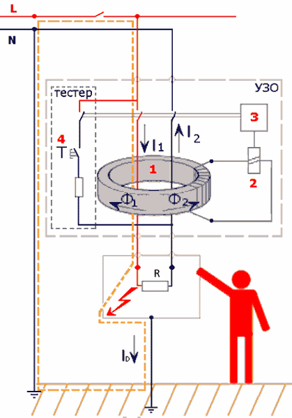
Schematic diagram of the operation of the RCD
The main element is the zero-sequence current transformer. Two windings in it are connected towards each other and connected to the neutral and phase wires, and the third - to the starting sensitive relay, instead of which there may be an electronic device. Relay connected to executive device control containing a group of contacts and a drive. To check the performance of the RCD, it has a test button.
When a load is connected to the output of the circuit, a load current appears in the circuit. The magnetic fluxes appearing in the core of the transformer cancel each other out. As a result, no current will be induced in the executive winding, and the polarized relay will be turned off.
If insulation damage occurs in contact with the metal parts of an electrical device, voltage appears on it. When a person touches open conductive parts, a leakage current I D (differential current) flows through him into the ground. As a result, different currents will flow through the main windings: I D \u003d I1 - I2. They will create different magnetic fluxes, as a result of which, as a result of superimposition on each other, a current will appear in the executive winding. If its value exceeds a predetermined level, the starting relay will work and transmit a signal to the actuator, which turns off the power electrical circuit from the installation where the breakdown occurred.
RCD serviceability control is carried out by pressing the test button. The resistor R is selected in size so that the artificially created leakage current is equal to the passport value. Thus, if the device turns off when you press the button, then it is working.
A device for a three-phase network works in a similar way, but four wires pass through the core opening (3 phase and 1 zero).
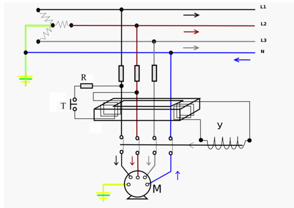
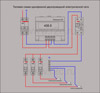
Scheme of operation of a three-phase RCD
During normal operation, the currents in the neutral and phase wires are summed up in such a way that the magnetic fluxes in the core cancel each other out. In secondary winding no current transformer. When a leakage current appears through one of the phases, the balance is disturbed and the resulting current in the secondary winding acts on the control element (U), which disconnects the consumer (M) from the network.
Leaks can occur not only in phase, but also in neutral wires. Protection reacts to them in the same way, but with the detection of insulation damage on the neutral, it may be necessary to dismantle the circuit. To avoid this, two- and four-pole switches are used, with the help of which phase and neutral wires are switched.
RCD is a complex and very sensitive device. You should choose devices on the market from well-known companies that have certificates of the established form with links to GOSTs. Small quantities of exported products may be counterfeit. The parameters of the purchased device should be correlated with the characteristics of well-known devices, for example, RCD-2000.
Wiring diagrams
The inclusion of leakage current protection in switchboards is carried out if the TNS or TN-C-S systems are used. In this case, the cases of all electrical appliances are connected to the zero ground bus PE. If the insulation is broken, the leakage current flows from the device case to the ground through the PE conductor, causing the protection to trip.
Whenever an RCD is connected, the following rules are taken into account:
- Separate tires are installed in the shield for the neutral conductor and grounding.
- The earth conductor is not involved in the connection of the device.
- Power is connected to the upper terminals of the device. In this case, the neutral is connected to the connector marked "N". It is unacceptable to confuse it with a phase!
- The permissible current of the device must be equal to or higher than the current of the machine.
Single phase input
The scheme provides for the mandatory separation of the zero bus (N) and ground (PE). If you put protection on individual parts, then this ensures a cascade shutdown in the system.
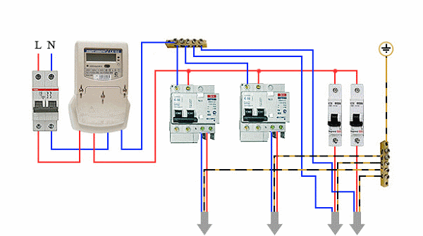
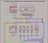
Scheme of connecting the RCD to a single-phase network
The scheme is simple and one of the most common. For RCDs, it is important not to make a mistake where the neutral (N), incoming (1) and outgoing (2) conductors are located. Always connect the RCD after the circuit breaker. Then, machines for individual lines can be connected to its output again.
Three-phase input
In a three-phase circuit, it is also possible to protect single-phase consumers. The inputs of the tires "zero" and "ground" are combined. The electric meter is installed between the main machine and the RCD.
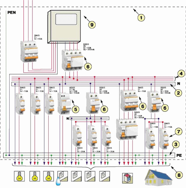
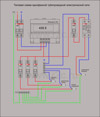
Three-phase RCD connection diagram
The load current of the RCD must be protected against overloads. To do this, it is picked up a step higher than that of the adjacent machine.
From the point of view of the use of RCDs, one should distinguish between the working neutral wire N and the protective earth zero PE. According to the first, the current flows in the mode normal operation, and according to the second only when an accident (leak) occurs.
Often there is an incorrect connection, causing a constant operation of the protection. At the same time, only it alone can cause a failure in the work of the whole group.
RCD in apartments
For an apartment, a two-pole RCD installation is selected. You also need to determine the values of the electric current that characterize it:
- cutoff exceeds the maximum current consumption by 25%;
- rated current for which the device is designed (indicated in the characteristic and must exceed the cut-off current);
- differential indicator of protection operation.
For an apartment, a device is selected with alternating current. With a large number of equipment, unreasonable tripping of the RCD is possible. To prevent this from happening, the threshold current value is increased to the maximum acceptable and safe for humans (30 mA).
The device is mounted in a shield on DIN rails or through special holes. It is marked with phase and neutral wires. Entry is at the top and exit is at the bottom.
Single-level protection with one device at the entrance allows you to completely stop the supply of electricity to the apartment. It is also installed on separate devices, for example, on a washing machine or an electric stove.
If you place the RCD in separate sections, the circuit will turn out to be cumbersome, but the shutdowns will be autonomous. For a separate device, the connection is made in front of the machine.
Common connection errors.
- Plexus of zero wires into a knot. As a result, unexpected triggers occur.
- Making homemade grounding is not according to the rules (resistance above 4 ohms).
- Connecting "zero" to "ground" leads to periodic power outages.
RCD in a private house
Private homeowners use a large number of devices that require an individual RCD. These include washing machine, electric heating system boiler, sauna oven, machine tools, welding transformer and other equipment. The longer the list, the greater the probability of failure of its elements.
For an individual house, a TT system with dead neutral grounding and connection of the conductive parts of the devices to an independent ground is suitable. It is most often made modular-pin.
RCD is placed in the shield. Four-pole and two-pole devices are used, depending on which consumers are connected: single-phase or three-phase. The principle of cascading remains, but the circuit is more complicated. The input is made three-phase, and there are much more consumers than in an apartment. General rules protection connections are the same as in the apartment.
In a private house, difautomats are often used, combining the functions of an RCD circuit breaker. Its advantages are the following:
- less space in the shield;
- ease of installation;
- operation due to leakage, short circuit or overload;
- the price is lower than that of two separate devices, the functions of which it combines.
Similarly, RCD difautomats have many connection options: with and without grounding, in a selective or non-selective way. The phase and zero of the circuit are also connected to them, which cannot be combined with grounding, since the currents in these conductors are fundamentally different.
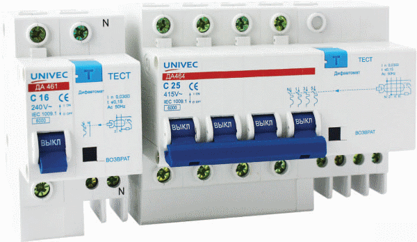
Differential machines in a private house
Disadvantage: in case of failure, you have to buy a difavtomat again, which is equivalent to replacing two devices at once. Also, not everyone knows how to use such sophisticated equipment and prefer to get by with some machines. But at the same time, connecting grounding to instrument cases without RCDs or difavtomatov is unacceptable. Conventional machines do not provide the network disconnection speed necessary for human safety.
The rules for the use of RCDs are also relevant for differential automata.
RCD connection. Video
This video will tell you in detail about the connection diagram of the residual current device.
The action of the residual current device is based on limiting the time for the flow of electric current through the human body (by quickly turning it off) in case of accidental contact with live parts of electrical installations. Some schemes for its connection also provide for turning off the network immediately when a leakage current occurs through the ground wire.
With proper installation and maintenance, RCDs ensure the safe use of electrical appliances in an apartment and house. Reliable are electromechanical protection devices against electric shock that meet the requirements of GOSTs.
RCD is necessary in modern housing, because its cost is immeasurably lower than that of modern household and electronic equipment, which can fail, but the most important thing is to ensure electrical safety.
09.10.2014Single-phase and three-phase electrical network
Electricity is supplied to the end consumer through power lines, and since they high voltage, this energy cannot be used without transformation. To reduce the voltage, special systems are used - transformer substations; they convert the high voltage to the optimum value.
To provide the house with power, a three-phase or single-phase network scheme can be used, their features will be discussed below.
Transformer substation
The transformer substation is designed to receive electricity from power lines, convert it and distribute it. The substation includes the following equipment: a step-down transformer, an electricity distribution device (ED) and a control unit.
Outside the city, pole and mast substations are most widely used. The main device of the substation is a one- or three-phase transformer that lowers the voltage. Most often in rural areas, a single-phase network scheme is used, which operates in conjunction with three-phase transformers.
The voltage is reduced to the nominal level and after conversion it can be either 380 V (linear) or 220 V (phase). Accordingly, the power supply received by consumers is called three-phase or single-phase.
Single phase power supply
In order to provide objects with power in a single-phase network scheme, two lines are used: a phase and a neutral working wire. Together they form a single-phase electrical network. The nominal voltage in it is 220 V.
Connection to a single-phase network according to this scheme does not provide for grounding. Now it is used much less frequently - it can be found mainly in buildings that are part of the old housing stock.
Single-phase two-wire network
A single-phase network can be two- or three-wire. One of the signs of a two-wire electrical network is the use of aluminum conductors. In three-wire networks, in addition to standard wires (phase and zero), there is also a protective one that performs the function of grounding.
Using a single-phase network scheme of this type allows you to organize additional protection dwellers from impact electric shock and avoid burnout electrical appliances. Ground wire (PE) connected to the enclosures household appliances, as soon as there is a short circuit of the phase to the case, the equipment is turned off.
In the construction of modern buildings, it is mainly used to connect to a single-phase network with three conductors, much less often with one.
Three-phase power supply
Three-phase power involves the introduction of three supply phases into the building, designated L1, L2, L3, and the neutral conductor N. The nominal operating voltage between any pair of phase wires is 380 V, and between the “zero” wire and each of the phase wires - 220 C. Using a three-phase network scheme allows you to provide equipment with electricity with a voltage of 220 or 380 volts. The wiring coming from the electrical panel is laid through the dwelling in accordance with the project.
One of the most important tasks when connecting to a three-phase network is to correctly calculate the load on each of the three phases, since its uneven distribution can cause phase imbalance. A significant imbalance often leads to emergency situations, including critical ones, when one of the phases burns. Four- or five-core cables are used to distribute three-phase electricity throughout the facility.
Three-phase network with four-wire cable
To supply electricity to the devices, three phase wires and a working zero are used.
From switchboard two wires are laid to sockets and lighting equipment: zero working in combination with each phase. As a result, the devices are provided with electricity having a voltage of 220 V.
The following phase designations are used in the power supply diagram: A, B, C.
Five-wire three-phase electrical network
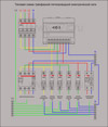
The fundamental difference between a four-wire power supply and a five-wire power supply is the presence of a ground wire, designated PE. Naturally, connecting to a three-phase network with five conductors provides higher security than using four conductors.
The greatest difficulty in designing three-phase electrical networks is to evenly distribute the load between the phases. When performing calculations, one should not be guided by Ohm's law - in such cases, it is necessary to use the power factor (denoted cosf) and demand - Kspros. Traditionally, for residential facilities, cosf is taken equal to 0.9-0.93, and the demand coefficient for apartments (if the number of consumers exceeds 5) is taken into account equal to 0.8.
We advise you to read
, diagnosis, treatment Treatment of urogenital chlamydia") Chlamydia urogenital - description, causes, symptoms (signs), diagnosis, treatment Treatment of urogenital chlamydia
Chlamydia urogenital - description, causes, symptoms (signs), diagnosis, treatment Treatment of urogenital chlamydia The benefits and significance of hydroamino acid threonine for the human body L threonine what
 To wait or not to wait for a guy from the army For what reason can they be commissioned from the army
 Baked apples with cottage cheese Baked apples with cottage cheese

