Getting a three-phase current.
A polyphase system is a system alternating current, consisting of several circuits in which the emf. energy sources have the same frequency, but are shifted in phase. A single-phase circuit in such a system is called a phase. Each e.m.f. can act in its own circuit and not be associated with other emfs. In this case, the electrical system is called uncoupled. Wide application In practice, coupled multi-phase systems have been obtained, in which the individual phases are electrically connected to each other.
Compared with single-phase current, multi-phase current has a number of advantages. To transmit the same power, a smaller cross-section of wires is required. AC motors and appliances use a rotating magnetic field generated by stationary coils or windings.
Rice. one
Of all the multi-phase current systems, three-phase current has become widespread in practice. The three-phase current flow can be explained as follows. If in a uniform magnetic field (Fig. 1) three turns are placed at an angle 120° one to the other, and rotate them with a constant angular velocity, emfs will be induced in the coils, which will also be phase shifted by 120°. In industry, to obtain a three-phase current, three windings are made on the stator of an alternator, shifted one relative to the other by 120°. Such windings are called generator phases.
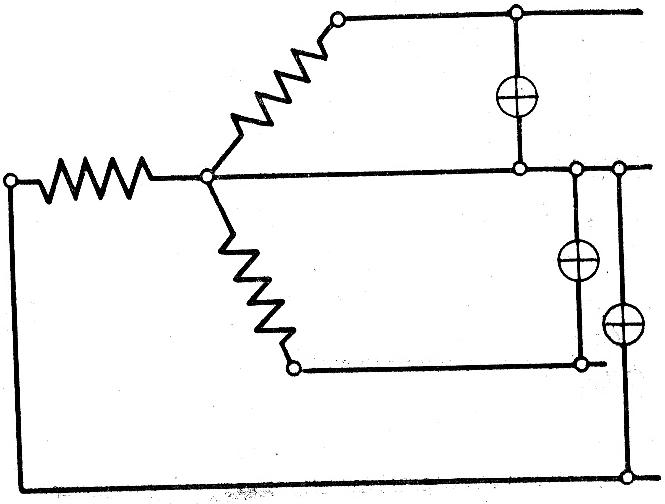
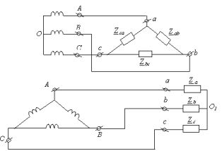
Rice. 2
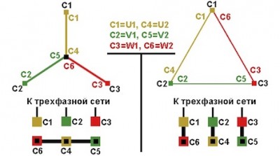
Star connections. By connecting the phase windings of the generator or consumer in such a way that the ends of the windings are closed into one common point, and connecting the beginning of the windings to the linear wires, we get a connection called a star (Fig. 2). Thus, we see that in the formation of a three-phase system connected in a star from three single-phase AC systems, only four wires are required instead of six. Conventionally, a star connection is indicated by the sign Y . The points at which the ends of the phase windings are connected are called zero, and the wire connecting them is called zero or neutral. Three wires connecting the free ends of the generator phases with the ends of the consumer phases are called linear.
With a uniformly loaded three-phase symmetrical system, a neutral wire is not needed; all power can be transmitted over three wires. However, when single-phase consumers are included in the electrical circuit, it is impossible to achieve a uniform loading of the phases. Therefore, in such cases, a neutral wire is necessary, although its cross section is equal to half the cross section of a linear wire.
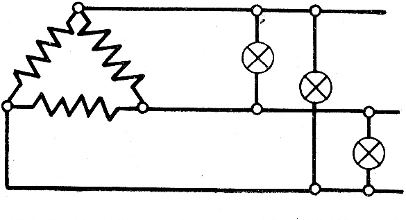
Rice. 3
With such a connection, the end of the first phase is connected to the beginning of the second, the end of the second - to the beginning of the third, and the end of the third - to the beginning of the first phase, and linear wires are connected to the connection points of the phases (Fig. 3). The triangle connection is conventionally denoted by the sign Δ .
When connected by a triangle, the phases of the generator form a closed circuit with little resistance. If the windings are connected incorrectly, the emf. may double. With a low resistance of the circuit, a mode close to a short circuit can be established.
When connected in a delta, each phase winding creates line voltage. The phase voltage in this case is equal to the linear voltage. The triangle connection is used for lighting and power loads.
In three-phase current motors, all six ends of the three windings are usually output, which, if desired, can be connected in a star or delta.
In this short article, without going into the history of AC networks, we will understand the relationship between phase and linear voltages. We will answer questions about what phase voltage is and what linear voltage is, how they relate to each other and why these relationships are exactly like that.
It's no secret that today electricity from generating plants is supplied to consumers by high voltage lines power lines with a frequency of 50 Hz. On the transformer substations the high sinusoidal voltage is lowered and distributed to consumers at the level of 220 or 380 volts. Somewhere the network is single-phase, somewhere three-phase, but let's figure it out.
Effective value and amplitude value of voltage
First of all, we note that when they say 220 or 380 volts, they mean the effective voltage values, expressed in mathematical language - RMS voltages. What does it mean?
This means that in fact the amplitude Um (maximum) of a sinusoidal voltage, phase Umf or linear Uml, is always greater than this effective value. For a sinusoidal voltage, its amplitude is greater than the effective value by the root of 2 times, that is, 1.414 times.
So for a phase voltage of 220 volts, the amplitude is 310 volts, and for a line voltage of 380 volts, the amplitude will be 537 volts. And given that the voltage in the network is never stable, then these values \u200b\u200bcan be either lower or higher. This circumstance should always be taken into account, for example, when choosing capacitors for a three-phase asynchronous motor.
Phase mains voltage
The windings of the generator are connected according to the "star" scheme, and are united by the ends of X, Y and Z at one point (in the center of the star), which is called the neutral or zero point of the generator. This is a four-wire three-phase circuit. The line wires L1, L2 and L3 are connected to the terminals of the windings A, B and C, and the neutral wire N is connected to the zero point.
The voltages between terminal A and zero point, B and zero point, C and zero point, are called phase voltages, they are denoted by Ua, Ub and Uc, but since the network is symmetrical, you can simply write Uf - phase voltage.
In three-phase AC networks in most countries, the standard phase voltage is approximately 220 volts - the voltage between the phase wire and the neutral point, which is usually grounded, and its potential is taken to be zero, which is why it is also called zero point.
Line voltage three-phase network
The voltages between terminal A and terminal B, between terminal B and terminal C, between terminal C and terminal A, are called linear voltages, that is, they are voltages between the linear conductors of a three-phase network. They are designated Uab, Ubc, Uca, or you can simply write Ul.
The standard line voltage in most countries is approximately 380 volts. It is easy to see in this case that 380 is 1.727 times greater than 220, and, neglecting losses, it is clear that this is Square root out of 3, that is 1.732. Of course, the voltage in the network fluctuates all the time in one direction or another depending on the current load of the network, but the ratio between linear and phase voltages is exactly the same.
In electrical engineering, the vector image method is often used. The method is based on the position that when a certain vector U rotates around the origin with a constant angular velocity ω, its projection onto the Y axis is proportional to the sine of ωt, that is, the sine of the angle ω between the vector U and the X axis, which is determined at each moment of time.
The graph of the dependence of the projection value on time is a sinusoid. And if the voltage amplitude is the length of the vector U, then the projection that changes with time is the current voltage value, and the sinusoid U(ωt) reflects the voltage dynamics.
So, if we now depict a vector diagram of three-phase voltages, it turns out that there are identical angles of 120 ° between the vectors of the three phases, and then if the lengths of the vectors are the effective values of the phase voltages Uf, then in order to find the linear voltages Ul, it is necessary to calculate the DIFFERENCE of any pair vectors of two phase voltages. For example Ua - Ub.
Having completed the construction by the parallelogram method, we will see that the vector Ul \u003d Ua + (-Ub), and as a result Ul \u003d 1.732 Uf. Hence it turns out that if the standard phase voltages are 220 volts, then the corresponding linear voltages will be 380 volts.
Content:One of the options for systems of multi-phase electrical circuits is a three-phase circuit. In multiphase electrical circuits, the action of sinusoidal electromotive forces with the same frequency occurs. They differ from each other in phase and are created from a common source of energy. In three-phase circuits, important parameters are phase and line voltage, which differ in their electrical characteristics.
What is a phase
Each part of a polyphase system that has the same current characteristic is called a phase. Therefore, the definition of the phase has a double meaning in electrical engineering. Firstly, as a value that changes sinusoidally, and secondly, as a separate part in a system of multi-phase electrical circuits. The number of phases determines the name of the circuits: two-phase, six-phase, etc.
The most common circuits in modern energy are three-phase. They have a number of advantages over other types of circuits, both single-phase and multi-phase. They are more economical in the production and transmission of electricity. Three-phase voltage results from the rotation of the magnet inside the coil. With its help, a rotating circular one is quite simply formed, which ensures the work induction motors. This phenomenon is known as EMF or otherwise, electromotive force induction.
The rotating magnet is called the rotor, and the coils around it form the stator. AC voltage is obtained by converting constant voltage when the straight line assumes a sinusoidal configuration with varying positive and negative values.
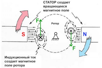
The change in the magnetic flux occurs due to the rotation of the rotor, which leads to the formation of an alternating voltage. The stator has three coils, each with its own separate electrical circuit. Each coil is shifted relative to each other by 120 degrees around the circumference. Under the action of a rotating magnet in all coils, the same AC voltage between phases in a three-phase network.
Three-phase circuits make it possible to obtain two operating voltages on one installation - phase and linear.
Phase and line voltage in three-phase circuits
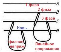
Phase voltage - occurs between the beginning and end of any phase. In another way, it is also defined as the voltage between one of the phase wires and the neutral wire.
Linear - is defined as interphase or between phase - arising between two wires or identical terminals of different phases.
Considering phase and linear voltages and currents, it should be noted that the phase voltage indicator is approximately 58% of the linear voltage parameters. Thus, under normal operating conditions, the linear indicators are the same and exceed the phase ones by 1.73 times. That is, if the linear voltage is 380, what is the phase voltage can be determined using this coefficient.
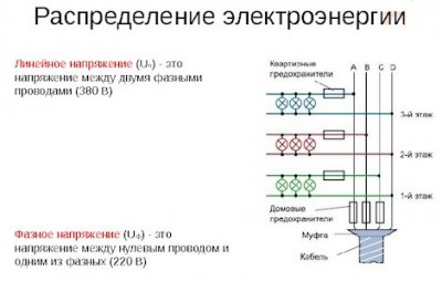
In a three-phase network, the voltage is usually estimated from line voltage data. For three-phase lines that depart from the substation, a linear voltage of 380 volts is set. This corresponds to a phase of 220 volts. In three-phase four-wire networks, the rated voltage is indicated with the designation of both values \u200b\u200b- 380/220 V. This means that both devices with 380 volts and single-phase devices with 220 volts are connected to such a network.
The most widespread is the three-phase 380/220 volt system with a grounded neutral wire. Single-phase electrical appliances for 220 volts are connected to line voltage between any pair of phase wires. Three-phase electrical appliances are connected to three different phase wires. In the latter case, the use of a neutral wire is not required, while increasing the risk of electric shock when the insulation is broken.
The difference between line voltage and phase
Before considering the practical significance of these parameters, it is necessary to know exactly how the linear and phase voltages differ from each other. Defined interfacial voltage in three-phase circuit can occur either between two phases, or between one of the phases and the neutral wire. Such interaction becomes possible due to the use of a four-wire three-phase circuit in the circuit. Its main characteristics are voltage and frequency.
The voltage that occurs between two phase conductors is considered linear, and between phase and zero, phase occurs. Line voltage is used to calculate currents and other parameters of a three-phase circuit. It is possible to connect to such circuits not only three-phase contacts, but also single-phase, for example, various household appliances. Rated value line voltage is 380 V. Sometimes it changes under the influence of various factors that appear in local network. Thus, all the main differences between both types of voltages lie in the methods of connecting the windings.
Line voltage has become the most widespread, due to the safe use and convenient distribution of networks. A multimeter is enough to measure it, while determining the characteristics of the phase voltage requires the use of voltmeters, current sensors and other special devices.
Control and alignment of this parameter is carried out using . This device ensures the maintenance of this indicator at the standard level, including it normalizes the increased voltage.
Use of line and phase voltage
A classic example of the use of line and phase voltages are the connections used at start-up. three-phase generator. Its design includes primary and secondary windings, which can be connected by a star or a triangle.
The "triangle" scheme involves the connection of the end of the first phase with the beginning of the second. In addition, each phase conductor is connected to the line wires of the current source. As a result, the currents are equalized, and the phase voltage becomes equal to the linear one. Electric motors and transformers are connected in the same way.
Another option is the "star" scheme. In this case, the beginnings of all windings are connected to the same network using jumpers. Thus, a current with the characteristics of this network will flow into the windings, and the phase-to-phase voltage will interact with all active contacts.
Between two phase conductors, it is sometimes referred to as interfacial or interfacial. The phase voltage is considered to be between the neutral wire and one of the phase wires. Under normal operating conditions, the line voltages are the same and exceed the phase voltages by 1.73 times.
Operating voltages of a three-phase circuit
Three-phase circuits have a number of advantages over multi-phase and single-phase circuits, with their help it is easy to obtain a rotational circular magnetic field, which ensures the operation of asynchronous motors. The voltage of a three-phase circuit is estimated by its linear voltage, for lines extending from substations it is set to 380 V, which corresponds to a phase voltage of 220 V. To indicate the rated voltage of a three-phase four-wire network, both values \u200b\u200bare used - 380/220 V, emphasizing that it can connect not only three-phase devices, designed for a rated voltage of 380 V, but also single-phase - for 220 V.
A phase is a part of a multi-phase system that has the same current characteristic. Regardless of the method of connecting the phases, there are three voltages of a three-phase circuit that are identical in terms of the effective value. They are shifted relative to each other in phase by an angle of 2π/3. A four-wire circuit, in addition to three linear voltages, also has three phase voltages.
Rated voltages
The most common nominal voltages for AC receivers are 220, 127 and 380 V. Voltages of 220 and 380 V are most often used to power industrial devices, and 127 and 220 V are used for household devices. All of them (127, 220 and 380 V) are considered to be the nominal voltages of a three-phase network. Their presence in a four-wire network makes it possible to connect single-phase receivers that are designed for 220 and 127 V or 380 and 220 V.
Differences in power distribution systems
The most widely used three-phase 380/220 V system with a grounded neutral, however, there are other ways to distribute electricity. For example, in a number of localities, you can find a three-phase system with an ungrounded isolated neutral and a line voltage of 220 V.
In this case, the neutral wire is not required, and the probability of defeat electric shock in case of insulation failure, it is reduced due to an ungrounded neutral. Three-phase receivers are connected to three phase wires, and single-phase receivers are connected to line voltage between any pair of phase wires.
We advise you to read
 Psychological characteristics of children in adolescence
 Transferring a child to another school - the procedure and necessary documents Whether to transfer a child to another school
, diagnosis, treatment Treatment of urogenital chlamydia") Chlamydia urogenital - description, causes, symptoms (signs), diagnosis, treatment Treatment of urogenital chlamydia
Chlamydia urogenital - description, causes, symptoms (signs), diagnosis, treatment Treatment of urogenital chlamydia The benefits and significance of hydroamino acid threonine for the human body L threonine what

