>> Physics Grade 11 >> Capacitor in a circuit alternating current
§ 33 AC CAPACITOR
Direct current cannot flow through a circuit containing a capacitor. Indeed, in fact, in this case, the circuit turns out to be open, since the capacitor plates are separated by a dielectric.
Alternating current can flow through a circuit containing a capacitor. This can be verified by a simple experiment.
Let us have sources of direct and alternating voltages, and the direct voltage at the terminals of the source is equal to the effective value of the alternating voltage. The circuit consists of a capacitor and an incandescent lamp (Fig. 4.13) connected in series. When turned on constant voltage(the switch is turned to the left, the circuit is connected to the points AA") the lamp does not light. But when the AC voltage is turned on (the switch is turned to the right, the circuit is connected to the points BB") the lamp lights up if the capacitance of the capacitor is large enough.
How can alternating current flow through the circuit if it is actually open (charges cannot move between the capacitor plates)? The thing is that there is a periodic charging and discharging of the capacitor under the action of an alternating voltage. The current flowing in the circuit when the capacitor is recharged heats the lamp filament.
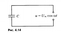
Let's establish how the current strength changes over time in a circuit containing only a capacitor, if the resistance of the wires and capacitor plates can be neglected (Fig. 4.14).
Capacitor voltage
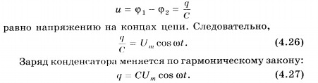
The current strength, which is the derivative of the charge with respect to time, is equal to:

Consequently, current fluctuations are ahead in phase of voltage fluctuations on the capacitor by (Fig. 4.15). 
The amplitude of the current strength is:
I m = U m C. (4.29)
If we introduce the designation
and instead of the amplitudes of the current and voltage, use their effective values, then we get
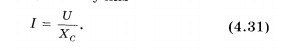
The value of X c, the reciprocal of the product C of the cyclic frequency and the electric capacitance of the capacitor, is called capacitance. The role of this quantity is similar to the role of active resistance R in Ohm's law (see formula (4.17)). The effective value of the current strength is related to the effective value of the voltage across the capacitor in the same way that the current strength and voltage are related according to Ohm's law for a section of the DC circuit. This allows us to consider the value of X with as the resistance of the capacitor to alternating current (capacitance).
The larger the capacitance of the capacitor, the greater the recharge current. This is easy to detect by increasing the incandescence of the lamp with an increase in the capacitance of the capacitor. While the DC resistance of a capacitor is infinite, its AC resistance is finite X c . As the capacity increases, it decreases. It also decreases with increasing frequency.
In conclusion, we note that during a quarter of the period when the capacitor is charged to maximum voltage, energy enters the circuit and is stored in the capacitor in the form of energy electric field. In the next quarter of the period, when the capacitor is discharged, this energy is returned to the network.
The resistance of a circuit with a capacitor is inversely proportional to the product of the cyclic frequency and the electrical capacity. Fluctuations in current are ahead in phase of voltage fluctuations by .
1. How are the effective values of current and voltage on a capacitor in an alternating current circuit related!
2. Is energy released in a circuit containing only a capacitor, if the active resistance of the circuit can be neglected!
3. The circuit breaker is a kind of capacitor. Why does the switch reliably open the circuit!
What is alternating current
If we consider direct current, then it may not always be perfectly constant: the voltage at the output of the source may depend on the load or on the degree of discharge of the battery or galvanic battery. Even with a constant stabilized voltage, the current in the external circuit depends on the load, which confirms Ohm's law. It turns out that this is also not quite a direct current, but such a current cannot be called alternating either, since it does not change direction.
A variable is usually called a voltage or current, the direction and magnitude of which do not change under the influence of external factors, for example, loads, but quite “independently”: this is how the generator produces it. In addition, these changes should be periodic, i.e. recurring after a certain period of time, called a period.
If the voltage or current changes at random, without caring about the periodicity and other regularities, such a signal is called noise. A classic example is "snow" on a TV screen with a weak terrestrial signal. Examples of some periodic electrical signals are shown in Figure 1.
For direct current, there are only two characteristics: this is the polarity and the source voltage. In the case of alternating current, these two quantities are clearly not enough, so several more parameters appear: amplitude, frequency, period, phase, instantaneous and effective value.

Picture 1.
Most often in technology one has to deal with sinusoidal oscillations, and not only in electrical engineering. Imagine a car wheel. When driving uniformly on a good level road, the center of the wheel describes a straight line parallel to the road surface. At the same time, any point on the periphery of the wheel moves along a sinusoid relative to the straight line just mentioned.
This can be confirmed by Figure 2, which shows a graphical method for constructing a sinusoid: whoever taught drawing well, he perfectly understands how such constructions are performed.
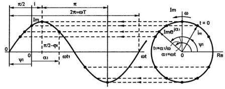
Figure 2.
From the school physics course, it is known that the sinusoid is the most common and suitable for studying the periodic curve. In exactly the same way, sinusoidal oscillations are obtained in alternators, which is due to their mechanical design.
Figure 3 shows a graph of a sinusoidal current.

Figure 3
It is easy to see that the magnitude of the current varies with time, so the y-axis is indicated in the figure as i(t), - a function of the current from time. The full period of the current is indicated by a solid line and has a period T. If you start from the origin, you can see that the current first increases, reaches Imax, passes through zero, decreases to -Imax, after which it increases and reaches zero. Then the next period begins, which is shown by the dotted line.
As mathematical formula current behavior is written as follows: i(t)= Imax*sin(ω*t±φ).
Here i(t) is the instantaneous value of the current, which depends on time, Imax is the amplitude value (maximum deviation from the equilibrium state), ω is the circular frequency (2*π*f), φ is the phase angle.
Circular frequency ω is measured in radians per second, phase angle φ is measured in radians or degrees. The latter makes sense only when there are two sinusoidal currents. For example, in circuits with current leads the voltage by 90˚ or exactly a quarter of the period, which is shown in Figure 4. If there is only one sinusoidal current, then you can move it along the ordinate axis as you like, and nothing will change from this.
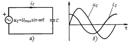
Figure 4 In circuits with a capacitor, the current leads the voltage by a quarter of a period.
The physical meaning of the circular frequency ω is what angle in radians the sinusoid will “run” in one second.
Period - T is the time it takes for the sine wave to complete one complete oscillation. The same applies to vibrations of another form, for example, rectangular or triangular. The period is measured in seconds or smaller units: milliseconds, microseconds, or nanoseconds.
Another parameter of any periodic signal, including a sinusoid, is the frequency, how many oscillations the signal will make in 1 second. The unit of frequency is the hertz (Hz), named after the 19th-century scientist Heinrich Hertz. So, the frequency of 1 Hz is nothing more than one oscillation / second. For example, the frequency of the lighting network is 50 Hz, that is, exactly 50 periods of the sinusoid pass per second.
If the current period is known (you can), then the formula will help you find out the frequency of the signal: f \u003d 1 / T. In this case, if the time is expressed in seconds, then the result will be in Hertz. Conversely, T=1/f, frequency in Hz, time is in seconds. For example, when the period will be 1/50=0.02 sec, or 20 milliseconds. In electricity, higher frequencies are more often used: kHz - kilohertz, MHz - megahertz (thousands and millions of oscillations per second), etc.
All that has been said for current is also true for alternating voltage: it is enough to simply change the letter I to U in Fig. 6. The formula will look like this: u(t)=Umax*sin(ω*t±φ).
These explanations are sufficient to return to experiences with capacitors and explain their physical meaning.
The capacitor conducts alternating current, which was shown in the circuit in Figure 3 (see article -). The brightness of the lamp glow increases when an additional capacitor is connected. When capacitors are connected in parallel, their capacitances simply add up, so we can assume that the capacitance Xc depends on the capacitance. In addition, it also depends on the frequency of the current, and therefore the formula looks like this: Xc=1/2*π*f*C.
It follows from the formula that with an increase in the capacitance of the capacitor and the frequency of the alternating voltage, the reactance Xc decreases. These dependencies are shown in Figure 5.

Figure 5. Capacitor reactance versus capacitance
If we substitute the frequency in Hertz into the formula, and the capacitance in Farads, then the result will be in Ohms.
Will the capacitor get hot?
Now let's recall the experience with a capacitor and an electric meter, why is it not spinning? The fact is that the meter counts active energy when the consumer is a purely active load, for example, incandescent lamps, an electric kettle or an electric stove. For such consumers, voltage and current are in phase, have the same sign: if you multiply two negative numbers (voltage and current during a negative half-cycle), the result, according to the laws of mathematics, is still positive. Therefore, the power of such consumers is always positive, i.e. goes into the load and is released as heat, as shown in Figure 6 by the dotted line.
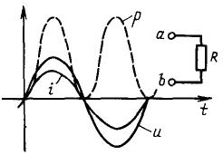
Figure 6
In the case when a capacitor is included in the AC circuit, the current and voltage are out of phase: the current leads the voltage by 90˚, which leads to the fact that a combination is obtained when the current and voltage have different signs.
Figure 7
At these moments, the power is negative. In other words, when the power is positive, the capacitor is charged, and when it is negative, the stored energy is given back to the source. Therefore, on average, it turns out by zeros and there is simply nothing to count here.
The capacitor, if of course it is serviceable, will not even heat up at all. Therefore, often a capacitor is called a wattless resistance, which allows it to be used in transformerless low-power power supplies. Although such blocks are not recommended due to their danger, it is still necessary to do this sometimes.
Before installing in such a block quenching capacitor, it should be checked by simply plugging it into the network: if the capacitor has not heated up in half an hour, then it can be safely included in the circuit. Otherwise, it will simply have to be thrown away without regret.
What does the voltmeter show?
In the manufacture and repair of various devices, although not very often, it is necessary to measure alternating voltages and even currents. If the sinusoid behaves so restlessly, then up, then down, what will an ordinary voltmeter show?
The average value of a periodic signal, in this case a sinusoid, is calculated as the area bounded by the x-axis and the graphical representation of the signal, divided by 2*π radians, or the period of the sinusoid. Since the upper and lower parts are exactly the same, but have different signs, the average value of the sinusoid is zero, and it is not necessary to measure it at all, and even simply pointless.
That's why measuring device shows us the RMS value of voltage or current. RMS is the value of the periodic current at which the same amount of heat is released on the same load as on DC. In other words, the light bulb shines with the same brightness.
This is described by formulas like this: Iavr = 0.707 * Imax = Imax / √2 for voltage, the formula is the same, it is enough to change one letter Uavr = 0.707 * Umax = Umax / √2. These are the values displayed by the meter. They can be substituted into formulas when calculating according to Ohm's law or when calculating power.
But this is not all that a capacitor is capable of in an AC network. The next article will look at the use of capacitors in pulse circuits, filters of high and low frequencies, in generators of sinusoid and rectangular impulses.
On the charge of a capacitor.
Let's close the chain. The circuit will charge the capacitor. This means that part of the electrons from the left side of the capacitor will go into the wire, and the same number of electrons will go from the wire to the right side of the capacitor. Both plates will be charged with opposite charges of the same magnitude.

Between the plates in the dielectric will be electric field.

Now let's break the chain. The capacitor will remain charged. We will shorten its lining with a piece of wire. The capacitor will instantly discharge. This means that an excess of electrons will go into the wire from the right plate, and a lack of electrons will enter the wire to the left plate. On both plates of electrons will be the same, the capacitor will be discharged.
What voltage is the capacitor charged to?
It charges up to the voltage that is applied to it from the power source.
Capacitor resistance.

Let's close the chain. The capacitor began to charge and immediately became a source of current, voltage, E.D.S.. The figure shows that the E.D.S. of the capacitor is directed against the current source charging it.
Opposition electromotive force of a charged capacitor the charge of this capacitor is called capacitive reactance.
All the energy expended by the current source to overcome the capacitive resistance is converted into the energy of the electric field of the capacitor. When the capacitor is discharged, all the energy of the electric field will return back to the circuit in the form of energy electric current. Thus, the capacitance is reactive, i.e. without causing irreversible loss of energy.
Why does direct current not pass through a capacitor, while alternating current does?
Turn on the DC circuit. The lamp flashes on and off, why? Because the capacitor charge current passed in the circuit. As soon as the capacitor is charged to the battery voltage, the current in the circuit will stop.
Now let's close the AC circuit. In the first quarter of the period, the voltage on the generator increases from 0 to a maximum. The circuit is charging a capacitor. In the second quarter of the period, the voltage on the generator decreases to zero. The capacitor is discharged through the generator. After that, the capacitor is charged and discharged again. Thus, in the circuit there are currents of charge and discharge of the capacitor. The lamp will be on constantly.
In a circuit with a capacitor, current flows in the entire closed circuit, including in the dielectric of the capacitor. In a charging capacitor, an electric field is formed that polarizes the dielectric. Polarization is the rotation of electrons in atoms in elongated orbits.
The simultaneous polarization of a huge number of atoms forms a current called displacement current. Thus, the current flows in the wires and in the dielectric, and the same value.
The capacitance of a capacitor is determined by the formula
Looking at the graph, we conclude: the current in a circuit with purely capacitive resistance leads the voltage by 90 0 .
The question arises how the current in the circuit can lead the voltage on the generator? In the circuit, current flows from two current sources in turn, from the generator and from the capacitor. When the generator voltage is zero, the current in the circuit is maximum. This is the discharge current of the capacitor.
About real capacitor
A real capacitor has two resistances at the same time: active and capacitive. They should be considered connected in series.
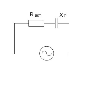
The voltage applied by the generator to the active resistance and the current flowing through the active resistance are in phase.
The voltage applied by the generator to the capacitance and the current flowing through the capacitance are shifted in phase by 90 0 . The resulting voltage applied by the generator to the capacitor can be determined by the parallelogram rule.
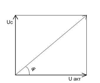
On the active resistance, the voltage U act and the current I are in phase. On the capacitance, the voltage U c lags behind the current I by 90 0 . The resulting voltage applied by the generator to the capacitor is determined by the parallelogram rule. This resulting voltage lags behind the current I by some angle φ, which is always less than 90 0 .
Determination of the resulting capacitor resistance
The resulting resistance of a capacitor cannot be found by summing up the values of its active and capacitive resistances. This is done according to the formula
1
An electric capacitor is an element of an electrical circuit designed to be used electrical capacitance.
A capacitor is a passive element in an electrical circuit. Usually consists of two electrodes in the form of plates or cylinders (called plates), separated by an insulator, the thickness of which is small compared to the dimensions of the plates. When a constant electrical voltage is applied to the capacitor plates, an electric charge flows into it, charging the capacitor plates, as a result of which an electric field arises between the plates. After this field has arisen, the current stops. A capacitor charged in this way can be disconnected from the source and used to store the energy stored in it. electrical energy. It was for the storage of electrical energy that the capacitor was invented in 1745 by physicists Ewald Jürgen von Kleistim from Germany and the Dutchman Peter van Muschenbroek. The first capacitor was made by them in the laboratory in Leiden and at the place of their ...
0 0
2
Does current flow through the capacitor?
Does electric current pass through the capacitor or not? Everyday amateur radio experience convincingly says that direct current does not pass, but alternating current does.
This is easy to confirm experimentally. You can light a light bulb by connecting it to an alternating current network through a capacitor. The loudspeaker or handsets will continue to work if they are connected to the receiver not directly, but through a capacitor.
A capacitor is two or more metal plates separated by a dielectric. This dielectric is most often mica, air or ceramics, which are the best insulators. It is quite natural that direct current cannot pass through such an insulator. But why does an alternating current pass through it? This seems all the more strange because the same ceramics in the form of, for example, porcelain rollers perfectly insulate AC wires, and mica perfectly performs the functions of an insulator ...
0 0
3
On the charge of a capacitor.
Let's close the chain. The circuit will charge the capacitor. This means that part of the electrons from the left side of the capacitor will go into the wire, and the same number of electrons will go from the wire to the right side of the capacitor. Both plates will be charged with opposite charges of the same magnitude.
Between the plates in the dielectric there will be an electric field.
Now let's break the chain. The capacitor will remain charged. We will shorten its lining with a piece of wire. The capacitor will instantly discharge. This means that an excess of electrons will go into the wire from the right plate, and a lack of electrons will enter the wire to the left plate. On both plates of electrons will be the same, the capacitor will be discharged.
What voltage is the capacitor charged to?
It charges up to the voltage that is applied to it from the power source.
Capacitor resistance.
Let's close...
0 0
4
08.11.2014 18:23
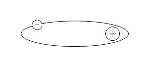
Do you remember what a capacitor is? Let me remind you. A capacitor, also known as a "conder", consists of two insulated plates. When a constant voltage is applied to the capacitor for a short time, it is charged and retains this charge. The capacitance of the capacitor depends on how many "places" the plates are designed for, and also depending on the distance between them. let's consider the simplest circuit already charged conder:
So, here we see eight "pluses" on one plate, and the same number of "minuses" on the other. Well, as you know, opposites attract) And the smaller the distance between the plates, the stronger "love. Therefore, plus "loves" minus, and since love is mutual, it means that minus also "loves" plus)). Therefore, this is attraction prevents the already charged capacitor from discharging.
In order to discharge the capacitor, it is enough to lay a "bridge" so that the "pluses" and "minuses" meet. That is stupid...
0 0
5
Elya / 18:21 08.12.2014 #
The capacitor is 2 pieces of foil (plate) with a piece of paper in the middle. (We won’t talk about mica, fluoroplastic, ceramic, electrolytes, etc. yet).
The paper does not conduct current, and therefore the capacitor does not conduct current.
If the current is alternating, then the electrons resorting to the first piece of foil charge it.
But, as you know, charges of the same name repel each other, so the electrons from the other piece run away.
How many electrons ran to one plate, so many ran away from the other.
The number of runaway electrons (current) depends on the voltage and capacitance of the capacitor (that is, on the size of the foil pieces and the thickness of the paper between them).
I'll try to explain in more detail on the fingers, or rather on the water
What is direct current? Imagine water (current) flowing through a hose (wire) in one direction.
What is alternating current? This is again water in the hose, but it no longer flows in one direction, but twitches back and forth with some amplitude ...
0 0
6
Does electric current pass through the capacitor or not?
Everyday amateur radio experience convincingly says that direct current does not pass, but alternating current does. This is easy to confirm experimentally. You can light a light bulb by connecting it to an alternating current network through a capacitor. The loudspeaker or handsets will continue to work if they are connected to the receiver not directly, but through a capacitor.
A capacitor is two or more metal plates separated by a dielectric. This dielectric is most often mica, air, or ceramic*, which are the best insulators. It is quite natural that direct current cannot pass through such an insulator. But why does an alternating current pass through it? This seems all the more strange because the same ceramics in the form of, for example, porcelain rollers perfectly insulate AC wires, and mica perfectly performs the functions of an insulator in soldering irons, electric irons and others ...
0 0
7
Subscribe to our Vkontakte group -, and Facebook - * Everyday amateur radio experience convincingly says that direct current does not pass through a capacitor, but alternating current does. For example, you can connect a lamp, or a speaker through a capacitor, and they will continue to work. In order to understand why this happens, let's look at the design of a capacitor. A capacitor is two or more metal plates separated by a dielectric. This dielectric is most often mica, air or ceramics, which are the best insulators. It is quite natural that direct current cannot pass through such an insulator. But why does an alternating current pass through it? This seems all the more strange because the same ceramics in the form of, for example, porcelain rollers perfectly insulate AC wires, and mica perfectly performs the functions of an insulator in soldering irons, electric irons and other heating devices that work properly from ...
0 0
8
Subscribe to our Vkontakte group - http://vk.com/chipidip,
and Facebook - https://www.facebook.com/chipidip
*
Everyday amateur radio experience convincingly says that direct current does not pass through a capacitor, but alternating current does. For example, you can connect a lamp, or a speaker through a capacitor, and they will continue to work. In order to understand why this happens, let's look at the design of a capacitor. A capacitor is two or more metal plates separated by a dielectric. This dielectric is most often mica, air or ceramics, which are the best insulators. It is quite natural that direct current cannot pass through such an insulator. But why does an alternating current pass through it? This seems all the more strange because the same ceramics in the form of, for example, porcelain rollers perfectly insulate AC wires, and mica perfectly performs the functions of an insulator in soldering irons, ...
0 0
When any capacitor is connected to electrical circuit direct current, a fast short-term pulse occurs. With its help, the capacitor is charged to the same extent as the energy source, after which, all movement of electric current stops. If it is disconnected from the current source, then in a very short time, under the influence of the load, a complete discharge will occur. When a lamp is connected as an indicator, it blinks once, and then goes out, since the discharge of the capacitor at direct current occurs in the form of a short-term pulse.
Capacitor operation with alternating current
A capacitor works in a completely different way in an alternating current circuit. In this case, the capacitor is charged and discharged, alternating with the frequency of oscillations that occur during AC voltage. The same incandescent lamp, placed in a circuit as an indicator, and connected in series, will, like a capacitor, emit continuous light, because the industrial-level frequency of oscillation is not perceived by the human eye.
Each capacitor has a capacitance, which determines the capacitance and frequency of AC cycles. According to the formula, this dependence is inversely proportional. In the presence of such resistance, there is no conversion of electrical and magnetic energy into heat. With more high frequency electric current, the capacitance decreases proportionally, and vice versa.
These important properties made it possible to use capacitors in an alternating current circuit as a quenching element instead of resistors in voltage dividers. This factor is especially important in case of voltage drops. In such a situation, instead of a capacitor, powerful resistors with large sizes would have to be used.
The main property of capacitors
Since the capacitor in the AC circuit is not subject to heat, there is no energy dissipation. This is due to the current shifting between each other and in the capacitor by 90 degrees. At the highest voltage, the current has a zero value, which means that no  work and heating does not occur. Therefore, capacitors in most cases are quite successfully used instead of resistors. At the same time, they have a disadvantage, which must be taken into account without fail. It consists in changing the alternating current in the circuit, causing a change in the voltage in the load. Another disadvantage is the lack of decoupling, and therefore their use has certain limitations and they are used with a stable resistance value. Such loads, most often, are heating elements.
However, its wide application capacitors found in various types frequency filters and resonant circuits.


