For the transmission and distribution of electricity, along with overhead power lines, power cable lines are used. Power cables are laid in the ground, water, as well as outdoor structures, in tunnels, channels, reinforced concrete blocks and inside buildings. They are used mainly for the transmission of electricity over relatively short distances and in cases where the construction of overhead lines is undesirable or unacceptable. Cable lines laid in the ground are not exposed to wind, ice, lightning discharges.
Damage to cable lines is not as dangerous to the public as a break in the wires of overhead lines. Power cable transmission lines are used for underground and underwater transmission of electricity at high and low voltages. The route is chosen based on the conditions of the lowest cable consumption and ensuring its greatest protection from mechanical damage during excavations, from corrosion, vibration, and overheating. Cable power lines are laid in trenches along the impassable part of the streets, under the sidewalks, in the yards.
The depth of the cable line in the ground for cables with voltage up to 10 kV is 0.7 m, and at the intersection of streets, roads and railways - 1 meter.
The cable should not pass under existing or proposed buildings and structures, under passages saturated with underground utilities.
At intersections with various pipelines (heat pipelines, water pipes, etc.), communication cables and other communications, power cables are laid in asbestos-cement pipes or reinforced concrete blocks, observing the distances between cables and other communications established (PUE). When cables pass through walls and ceilings, cables are laid in segments of non-metallic pipes.
After laying the ends of the cables must be temporarily sealed. Connection and termination of cables is carried out using cable sleeves and funnels. Cable lugs are used to terminate the cores. In addition, the cable in the trench is sprinkled on top with a layer of fine earth or sand 10 cm thick, and to protect it from mechanical damage, it is protected by covering it with a layer of red brick. On top of the brick, the trench is covered with soil excavated from it.
The greatest number of failures of 6-10 kV cable lines occurs when they are laid in trenches. This is due to the presence of mechanical damage, corrosion, precipitation, landslides and other soil deformations. Therefore, the method of laying cables in trenches is inferior to more progressive and reliable methods in operation - laying on overpasses, galleries, in tunnels, etc.
A significant number of failures occur due to cable damage due to cable factory defects, mechanical damage during laying or re-laying them during operation (breaks, dents, scuffs), as well as corrosion of the metal sheath.
Cable factory defects include: folds in paper tapes, transverse and longitudinal cuts and ruptures, gaps between paper tapes as a result of their coincidence, defects in cores and lead sheaths, etc. Many factory defects in cable insulation remain undetected during direct current tests
lead to an emergency breakdown of the cable during operation. Corrosion of the metal sheath of cables is caused by the action of stray currents or aggressive soils. Under operating conditions, there are individual cases of corrosion damage to the aluminum sheath of the AAShv cable due to damage to the PVC hose. A significant number of failures of cable lines occur due to damage to the couplings and terminations due to the poor quality of contact connections and core terminations (presence of deep pores, sharp edges and burrs, non-removed sprue profit, bitten or burnt core wires, etc.).
Failures of lead couplings occur due to unsatisfactory soldering of the lead body to the cable sheath, formation of voids during the restoration of insulation with rollers and rolls, underfilling of the cable mass, lack of control over the temperature of the casting and scalding masses, crystallization of the casting mass during operation, and due to other reasons. .
Failures of epoxy couplings are associated with the asymmetry of the cores inside the epoxy housing, the presence of pores and fistulas, the lack of necessary sealing, etc.
Significant number of termination failures indoor installation occurs due to the installation in damp and especially damp rooms of terminations not intended for these environments. Failures of epoxy terminations are explained by poor degreasing and processing of the ends of nayrite tubes, cracking of tubes, poor sealing of cores, etc.
Couplings and terminations and terminations, as a rule, cannot be repaired, therefore, after their failure, they are cut out and replaced with new ones.
Cable repair:
Determining the nature of cable damage - before starting work, measurements are made to determine the nature of the damage. Before measurements, the cable line must be disconnected from the supply source, and electrical receivers from the line. In most cases, the nature of the damage can be determined using a megohmmeter.
Determining the location of cable damage - is determined in two steps: first, the damage zone is found, then the location of the damage is specified directly on the route. The damage zone is determined: by the pulse method, by the oscillatory discharge method, by the capacitive method or by the loop method. The place of damage is specified using an acoustic or induction method.
Repair of cable armor - the damaged part is removed, after which the edge of the armor is soldered with a lead sheath. The lead sheath of the cable, not covered with armor, is coated with an anti-corrosion compound.
Repair of the lead sheath and checking of paper insulation - the type of repair is determined depending on whether moisture has penetrated into the cable or not. In doubtful cases, remove a part of the sheath on both sides of the place of its damage, inspect the belt insulation and check the top layer of insulation for the absence of moisture. To check, paper insulation tapes are removed from the damaged cable and immersed in paraffin heated to 150 ° C. Cracks and foaming indicate the penetration of moisture into the cable under the lead sheath. If there is no moisture inside the cable, a pipe (coupling) of the appropriate size with two filling holes is put on the damaged part of the sheath. After pouring the coupling with hot mastic and sealing the seam, a copper bandage is applied to it, which is soldered to the lead sheath. The pipe is made of rolled lead (two halves). It should be 70-80 mm larger than the bare part of the cable. If there is moisture inside the cable, the damaged section is cut out and a piece of cable is inserted instead of it, corresponding in brand, cross section and length to the one being repaired. Couplings are mounted on both sides of the cable insert.
Cable lines are designed to transmit electricity through one or more power cables with connectors and terminations. Power cables consist (Fig. 1) of one, two, three or four insulated conductors 1, which are in a sealed protective sheath 5.
Current-carrying conductors, copper or aluminum, can be single-wire and multi-wire. They are isolated from each other (2) and from the shell (4). Core insulation is made of rubber, plastic or, most often, impregnated cable paper.
The protective sheath (5) protects the insulation of the cable cores from moisture and air and is made of lead, aluminum, polyvinyl chloride and non-combustible rubber. To protect the sheath from damage during the application of armor and cable bends, a protective cover (6) impregnated with an anti-corrosion bitumen composition is applied to it. Armor (7), made of strip steel or galvanized wire, plays the role of protecting the shell from external mechanical influences. Outside, the cable is protected by a protective cover (8) on a synthetic or bitumen basis.
Picture 1. 1 - conductive wires; 2 - core insulation relative to other cores; 3 - paper filler; 4 - core insulation relative to the shell; 5 - protective shell; 6 - protective cover of the shell; 7 - steel armor; 8 - outer protective cover
To designate a power cable, indicate its brand, as well as the rated voltage and cross section of the cores. The marking depends on the material of the conductive wires, the hermetic sheath and the type of outer protective cover. For example, a four-core power cable with single-wire aluminum conductors in an aluminum sheath with an outer cover that allows laying in the ground, designed for voltages up to 1 kV, with a cross section of all conductors of 185 mm 2, has the following designation: AABv (ozh) 4 * 185-1 .
Designations of brands of cables corresponds to their design. Cables with paper insulation and aluminum conductors have the following brands: AAB, AAG, AAP, AASHv, ASB, ASBG, ASPG, ASShv. The first letter indicates the core material (A - aluminum, the absence of the letter A in front of the marking means the presence of a copper core), the second letter - the sheath material (A - aluminum, C - lead). The letter B means that the cable is armored with steel tapes; the letter G - the absence of an outer cover; Shv - the outer cover is made in the form of a PVC hose.
Insulation is designated: R - rubber, P - polyethylene, V - polyvinyl chloride, no designation - paper with normal impregnation.
Currently found wide application cables with XLPE insulation, which are available in three-core and single-core.
Armor is designated: when performed with steel tapes - B, with flat galvanized steel wire - P, with round galvanized steel wire - K.
For example, the SBShv cable brand denotes a cable with copper conductors in a lead sheath, armored with steel tape, with an outer cover in the form of a PVC hose.
Areas of use power cables With various types isolation are given in table. one.
Table 1. Fields of application of power cables with paper, plastic and rubber insulation in the absence of mechanical influences and tensile forces during operation
|
Place of laying |
Environmental conditions |
Paper insulated cables |
Cables with plastic and rubber insulation |
|
|
Corrosivity |
stray currents |
|||
|
In the ground (trench) |
AASHv, AASHp, AABL, ASB |
AVVG APsVG APvVG APVG AVVB |
||
|
AASHv, AASHp, AAB2l, ASB |
||||
|
AASHv, AABl, AASHp, AAB2l, ASB, ASBl |
||||
|
AASHv, AABv, AASHp, AAB2l, ASB2l, ASBl |
||||
|
AAB2lShv, ASBl, AAB2lShp, AABv, ASB2l |
||||
|
AASHp, AABv, ASB2l, ASB2lShv |
||||
|
In rooms (tunnels, channels, etc.): dry |
AVVG, AVRG, ANRG, APvVG, APVG, APvsVG, APsVG |
|||
|
Medium and high |
AASHv, ASSHv |
|||
|
fire hazardous |
AVVG, AVRG, APsVG, APvsVG, ANRG, ASRG |
|||
|
In hazardous areas |
SBG, SBShv |
VVG, VRG, NRG, SRG |
||
Note: P - polyethylene; PS - from self-extinguishing polyethylene; Pv - from vulcanizable polyethylene; Pvs - from vulcanizable self-extinguishing polyethylene; N - from nayrite (non-combustible) rubber; W - hose; l, 2l - reinforced and especially reinforced pillow under the shell.
Cables are laid in trenches, channels, tunnels, blocks, overpasses. Indoors, cables are laid on special steel structures, in trays and boxes.
The simplest is laying cables in trenches (Fig. 2). It is also economical in terms of non-ferrous metal consumption, since the permissible currents for cables are greater (about 1.3 times) when laying in the ground than in air.
Laying in trenches is not applicable:
in areas with a large number of cables;
with a high saturation of the territory with underground and surface technological and transport communications and other structures;
in areas where it is possible to spill hot metal or liquids that destroy the cable sheath;
in places where stray currents of dangerous values, high mechanical loads, soil erosion, etc. are possible.
Figure 2.
Experience in the operation of cables laid in earthen trenches has shown that cables are often damaged during any openings. When laying six or more cables in one trench, a very large reduction factor for the permissible current load is introduced. Therefore, you should not lay more than six cables in one trench.
With a large number of cables, two adjacent trenches are provided with a distance of 1.2 m between them.
An earthen trench for laying cables must have a depth of at least 800 mm. At the bottom of the trench, a soft cushion 100 mm thick is created from the sifted earth. The cable laying depth must be at least 700 mm. The width of the trench depends on the number of cables laid in it. The distance between several cables with voltage up to 10 kV must be at least 100 mm. The cables are laid at the bottom of the trench in one row and covered with a layer of soft soil or sand at least 100 mm thick. To protect a cable line with a voltage above 1 kV from mechanical damage, it is covered along its entire length over the top bedding with concrete slabs or bricks, and voltage lines up to 1 kV - only in places of probable rupture.
Cable lines are laid along the impassable part at a distance of at least: 600 mm from the foundations of buildings, 500 mm to pipelines, 2000 mm from heat pipelines.
The cable line is laid along the route, taking into account the lowest cable consumption and ensuring its safety from mechanical damage, corrosion, vibration, overheating and arson by an electric arc from nearby cables. To eliminate the risk of dangerous mechanical forces, the cables are laid with a margin in length, and a margin of 35 cm is left on both sides of the couplings in a vertical plane in the trench deepening.
During open horizontal laying of cables along structures and walls in collectors and channels, they are rigidly fixed at the ends, at bends and at couplings, installing supporting structures every 80-100 cm. In those places where there is a risk of mechanical damage, the cable is protected with an additional coating at a height of 2 m. Places for cable transitions from trenches to buildings, tunnels, through ceilings and roads should be organized using pipes or openings. This, in particular, protects the cable from vibrations and provides the possibility of repair without opening the roadbed.
In places of a sharp change in the direction of the cable laying, the radii of the internal bending curve of the cables are limited to avoid mechanical damage.
All cables are produced in segments of limited length, depending on its voltage and section. During the construction of cable lines, individual segments are connected to each other by means of couplings that seal the joints. For cables with voltage up to 1 kV, epoxy or cast-iron couplings are used (Fig. 3).
Figure 3 1 - body; 2 - three-phase cable; 3 - porcelain spacer; 4 - connecting clamp
For cables with plastic insulation, couplings are used from heat-shrinkable insulating tubes, the number of which corresponds to the number of cable cores, and one hose heat-shrinkable tube (Fig. 4). All heat shrink tubing has a hot melt adhesive on the inside surface. Insulating tubes insulate the conductive wires, and the hose pipe restores the sheath at the junction.
Figure 4. Joint for plastic insulated cable with voltage up to 1 kV
Terminations and terminations are used to connect cables to electrical devices of switchgear. On fig. 5 shows a mastic-filled three-phase termination outdoor installation with porcelain insulators for 10 kV cables.
Figure 5
For three-core plastic-insulated cables with a voltage of 10 kV, an end sleeve is used, shown in fig. 6. It consists of a heat-shrinkable glove 1, resistant to impact environment, and semi-conductive heat-shrinkable tubes 2, with the help of which three single-core cables are created at the end of a three-core cable. Insulating heat-shrinkable tubes 3 are put on separate cores. The required number of heat-shrinkable insulators 4 is mounted on them.
Figure 6
The metal sheaths of the mating cables are connected in the couplings to each other and to the coupling housings along the entire length of the line. In terminations, these shells are connected to the common ground loop of the object.
To improve reliability and durability, cable lines in urban areas are laid in special underground structures, which include:
collectors constructed for the joint laying of cables (power, control and communications), water and heat pipelines;
tunnels designed to accommodate power and control cables;
channels arranged on the territory of substations or distribution points, inside industrial premises used to place cable lines;
cable blocks made of pipes or concrete blocks with tubular channels and wells prepared in them.
Entrances to underground structures and hatches of wells must be locked. Tunnels and sewers should be provided with lighting and ventilation. All metal structures must be coated with non-combustible anti-corrosion varnishes.
At the present time, it is difficult to imagine a city, a village or even a separate cottage without electricity. People are strongly attached to household appliances, light, heat, that even a short-term lack of electricity causes tangible inconvenience and problems. Each power plant of any object must be connected to electrical network so that the energy can spread further. This connection is made thanks to special power lines.
What is cable and power lines
A cable line is a type of line that transmits impulses electrical energy over long distances. It consists of one or more cores, which are equipped with connecting lock or end sleeves and fasteners.
Power cable lines are the same cables, but with reinforced insulation that can withstand high voltage. They are made up of the following layers:
- conductive core;
- insulation of the core itself;
- paper filler;
- insulation of all cables in one sheath;
- protective shell;
- steel armor in the form of sheet steel;
- another protective cover.
Classification of cable lines
According to the conditions for passing the line, there are:
- underground;
- underwater;
- on buildings and structures.
These lines are used when it is not possible to install overhead lines. Protective type gasket contributes to the reliable protection of the cable from various atmospheric influences and mechanical damage. They are characterized by a high degree of reliability during the entire period of operation.
But, despite this, the following types of damage are possible:
- short circuit caused by aging of the insulating coating of the cores;
- mechanical damage;
- break lived.
That is why it is necessary to test power cable lines, which will help determine the "weak" areas of insulation, installation and connection defects.
They are carried out in accordance with the PUE and PTEEP.
How are cable lines labeled?
The marking of these lines and the installation of special identification marks are done according to the following principle: each line must have its own individual number and name. If it consists of several cores, then it is signed in the same way, only a letter is assigned to each cable (A, B, C, etc.).
In case of laying open lines of force a special tag must be present on the cable, on which the following characteristics are displayed: brand, section, voltage, number and name of the line. These tags must necessarily have appropriate resistance to various climatic conditions.
On closed lines, appropriate identification signs are installed at the end points, in wells and sewage chambers.
Engineering center "ProfEnergy" has everything necessary tools for high-quality testing of power cable lines, a well-coordinated team of professionals and licenses that give the right to carry out all the necessary tests and measurements. Leaving the choice on the electrical laboratory "ProfEnergia" you choose the reliable and high-quality operation of your equipment!
Page 1 of 8
Power cable line is a line for the transmission of electrical energy, consisting of one or more parallel cables with connecting cables. locking and end sleeves (terminals) and fasteners. In power cable lines, cables with paper and plastic insulation are most widely used. The type of insulation of power cables and their design affect not only the installation technology, but also the operating conditions of power cable lines. This applies in particular to plastic-insulated cables. So as a result of changing loads during operation and additional heating due to overloads and currents short circuit, pressure arises in the cable insulation from the polyethylene (polyvinyl chloride) that increases with heating, which can stretch the screens and cable sheaths, causing their residual deformation. During subsequent cooling, due to shrinkage, gas or vacuum inclusions are formed in the insulation, which are ionization centers. In this regard, the ionization characteristics of the cables will change. Comparative data on the value of the temperature coefficient of volume expansion of various materials used in the construction of power cables are given in table 1.
Table 1. Temperature coefficients of volumetric expansion of materials used in the construction of power cables
It should be noted that the highest value of the temperature coefficient of volume expansion occurs at temperatures of 75-125°C. corresponding to the heating of the insulation during short-term overloads and short-circuit currents.
Paper impregnated cable core insulation has high electrical characteristics. long service life and relatively high heating temperature. Cables with paper insulation retain their electrical characteristics better during operation with frequent overloads and additional heating associated with this.
To ensure long-term and trouble-free operation of cable lines, it is necessary that the temperature of the cores and cable insulation during operation does not exceed the permissible limits.
The long-term permissible temperature of conductive conductors and their permissible heating at short-circuit currents are determined by the cable insulation material. The maximum allowable temperatures of the cores of power cables for various core insulation materials are given in Table. 2.
Table 2. Maximum allowable core temperatures of power cables
|
core insulation |
Cable voltage, kV |
Long-term permissible temperature of cable cores, RS |
Permissible heating of cores at short-circuit currents, °С |
|
paper impregnated | |||
|
Plastic: | |||
|
PVC plastic compound | |||
|
polyethylene | |||
|
vulcanizing polyethylene | |||
|
Rubber | |||
|
Rubber increased heat resistance |
Note: Permissible heating of cable cores made of PVC and polyethylene in emergency mode should be no more than 80°C, of vulcanized polyethylene - 130°C.
The duration of operation of cables in emergency mode should not exceed 8 hours per day and 1000 hours. for the service life. Cable lines with a voltage of 6-10 kV, bearing loads less than the nominal ones, can be overloaded for a short time under the conditions given in Table. 3.
Table 3 Permissible overloads in relation to rated current cable lines with a voltage of 6-10 kV
Note: For cable lines that have been in operation for more than 15 years, overloads must be reduced by 10%. Overloading of cable lines for a voltage of 20 ÷ 35 kV is not allowed.
Any power cable line, in addition to its main element - the cable, contains connecting and termination couplings (terminals), which have a significant impact on the reliability of the entire cable line.
Currently, when mounting both end sleeves (terminals) and couplings, heat-shrinkable products made of radiation-modified polyethylene are widely used. Radiation exposure of polyethylene leads to the production of a qualitatively new electrical insulating material with unique sets of properties. So, its heat resistance increases from 80 °C to 300 °C for short-term operation and up to 150 °C for long-term operation. This material has high physical and mechanical properties: thermal stability, cold resistance, resistance to aggressive chemical environments, solvents, gasoline, oils. Along with significant elasticity, it has high dielectric properties, which are preserved at very low temperatures. Heat-shrinkable sleeves and terminations are mounted on both plastic and paper-impregnated cables.
The laid cable is exposed to aggressive components of the environment, which are usually chemical connectors diluted to one degree or another. The materials from which the sheath and armor of cables are made have different corrosion resistance.
Lead stable in solutions containing sulfuric, sulphurous, phosphoric, chromic and hydrofluoric acids. AT hydrochloric acid lead is stable at concentrations up to 10%.
The presence of chloride and sulfate salts in water or soil causes a sharp inhibition of lead corrosion. therefore, lead is stable in saline soils and seawater.
Nitric acid salts (nitrates) are highly corrosive to lead. This is very significant, since nitrates are formed in the soil in the process of microbiological decay and are introduced into it in the form of fertilizers. According to the degree of increase in their aggressiveness in relation to lead sheaths, soils can be distributed as follows:
a) solonchak; b) calcareous; c) sandy; d) black earth; e) clay; e) peat.
Carbon dioxide and phenol greatly enhance the corrosion of lead. Lead is stable in alkalis.
Aluminum stable in organic acids and unstable in hydrochloric, phosphoric, formic acids. as well as in alkalis. A highly aggressive effect on aluminum is exerted by salts, during the hydrolysis of which acids or alkalis are formed. Of the neutral salts (pH=7), salts containing chlorine are the most active, since the resulting chlorides destroy the protective film of aluminum; therefore, solonchak soils are the most aggressive for aluminum shells. Sea water, mainly due to the presence of chloride ions in it, is also a highly aggressive medium for aluminum. In solutions of sulfates, nitrates and chromium, aluminum is quite stable. Corrosion of aluminum is greatly enhanced by contact with a more electropositive metal such as lead, which is likely to occur when couplings are installed unless special measures are taken.
When mounting a lead coupling on a cable with an aluminum sheath, a lead-aluminum contact galvanic pair is formed, in which aluminum is the anode, which can cause destruction of the aluminum sheath several months after the coupling is installed. In this case, damage to the shell occurs at a distance of 10-15 cm from the neck of the coupling, i.e. at the place where protective covers are removed from the shell during installation. For elimination harmful action of similar galvanic pairs, the coupling and the bare areas of the aluminum sheath are covered with a cable composition of the MB-70 (60) brand, heated to 130 ° C, and an adhesive PVC tape is applied on top in two layers with a 50% overlap. A layer of tarred tape is applied over the adhesive tape, followed by coating it with a bituminous top coat of the brand BT-577.
PVC compound non-flammable, highly resistant to most acids, alkalis and organic solvents. However, it is destroyed by concentrated sulfuric and nitric acid, acetone and some other organic compounds. Under the influence of high temperature and solar radiation, PVC compound loses its plasticity and frost resistance.
Polyethylene possesses chemical resistance to acids, alkalis, solutions of salts and organic solvents. However, polyethylene under the influence of ultraviolet rays becomes brittle and loses its strength.
Rubber, used for sheathing cables, it resists well the action of oils, hydraulic and brake fluids, ultraviolet rays, as well as microorganisms. Destructive effect on rubber solutions of acids and alkalis at elevated temperatures.
Armor, made of low carbon steel, usually fails much earlier than the shell begins to corrode. Armor is highly corrosive in acids and very stable in alkalis. The destructive effect on it is sulfate-reducing bacteria that produce hydrogen sulfide and sulfides.
Covers of cable yarn and bitumen practically do not protect the sheath from contact with external environment and are quickly destroyed in soil conditions.
Electrochemical protection of cables against corrosion is carried out by cathodic polarization of their metal sheaths, and in some cases armor, i.e. superimposing negative potential on the latter. Depending on the way electrical protection cathodic polarization is achieved by attaching cathode station cables, drainage and tread protection to the sheaths. When choosing a method of protection, the main factor that causes corrosion in these specific conditions is taken into account.
The power cable brand characterizes the main structural elements and the scope of cable products.
Letter designations structural elements of the cable are given in table. four.
Table 4 Letter designations of structural elements of the cable
|
Structural element of the cable |
Material |
Letter designation |
|
Copper Aluminum |
No letter A |
|
|
core insulation |
No letter P V R |
|
|
Belt insulation |
Paper Polyethylene PVC Rubber |
No letter P V R |
|
Shell |
Lead Aluminum smooth Aluminum corrugated PVC Polyethylene flame retardant rubber |
S A A g |
|
Paper and bitumen Without cushion PE (hose) PVC: one layer of PVC-type plastic tape two layers of PVC-type plastic tape |
No letter b |
|
|
Steel tape Flat wire Round wire | ||
|
Outer cable cover |
Cable yarn Without outer cable cover Glass fiber yarn (flammable cable cover) Polyethylene hose PVC hose |
No letter |
Note: 1. The letters in the cable designation are arranged in accordance with the cable design, i.e. starting from the core material and ending with the outer cable cover.
2. If at the end of the letter part of the cable brand there is a letter "P", written through a dash, then this means that the cable has a flat shape in cross section, and not a round one.
3. The designation of the control cable differs from the designation of the power cable only in that the letter "K" is placed after the material of the cable core.
The letters are followed by numbers indicating the number of main insulated cores and their cross section (through the multiplication sign), as well as the rated voltage (through a dash). The number and cross-section of cores for cables with a zero core or grounding core is indicated by the sum of the numbers.
The most widely used cables are the following standard cross-sections of cores: 1.2; 1.5; 2.0;2.5; 3; four; 5; 6; eight; ten; 16; 25; 35; fifty; 70; 95; 120; 150; 185; 240 mm.
DEVICE AND INSTALLATION OF CABLE LINES
Power cable arrangement
For the transmission and distribution of electricity, along with overhead power lines, cable ones are used. They are mainly used to transmit electricity over relatively short distances and in cases where the construction of overhead lines is undesirable or unacceptable (for example, in built-up areas of industrial enterprises, in urban areas). The transmission of electricity through cable lines has become widespread, despite their higher cost compared to overhead lines, since cable lines have a number of advantages. Cable lines laid in the ground are not exposed to such external influences as ice, wind, dust, moisture, lightning discharges, damage in them is not as dangerous for the population as a break in the wires of overhead lines. In addition, the supply of electricity directly to consumers ( electric machines and devices) is practically possible only via cables. On overhead lines up to 35 kV, cable inserts are arranged when the construction of an overhead line is technically or economically impractical. Typically, such inserts are built at crossings over communication lines, automobile or railways, air lines power transmission lines, at the approaches to transformer substations, in the territories of settlements.
Fig.1. Power cable:
1 - conductive wires, 2, 3 - phase and belt insulation, 4 - shell, 5 - pillow, 6 - armor, 7 - outer protective layer
The main elements of the cable. A power cable (Fig. 1) is one or more insulated conductive cores enclosed in a sealed sheath, over which protective covers are applied.
The main structural elements of cables are: conductors 1, insulation 2
and 3,
hermetic protective shell 4,
protecting insulation from moisture and air, outer protective cover, consisting of cushion 5, armor 6
and outer protective layer 7, which reinforces the cable sheath and protects it from corrosion and mechanical damage. In addition, the cable design may include screens, fillers and neutral conductors.
Conductors consist of one or more twisted punctures covered with an insulating sheath. Depending on the number of current-carrying cores, power cables are made of one-, two-, three- and four-core. The most widely used are three- and four-core cables, since the majority of industrial consumers use three-phase alternating current. Three-core power cables are manufactured for an operating voltage of 1-35 kV, four-core - up to 1 kV. The fourth core of such cables is used as a neutral wire and, as a rule, has a cross section half that of the others.
For voltages of 110 and 220 kV, single-core low-pressure oil-filled cables in a corrugated sheath and high pressure in steel pipes.
Conductive single- and stranded conductors are made mainly from aluminum, less often from copper. Stranded conductors are made of several wires of the same diameter or in the form of a core wrapped in several rows of wires. The cross section of the cores can be round (Fig. 2, a, b), sector (Fig. 2, c, d) and segment (Fig.2. e). For a snug fit of the wires in a stranded core, as well as to ensure sufficient cable flexibility, the wires inside the core are twisted and sealed (Fig. 2, b, d, e). This significantly reduces the number of air inclusions, and also reduces the leakage of the impregnating composition, which is especially important for vertical and inclined cable laying.
Insulation provides the electrical strength of the current-carrying conductors and the cable as a whole. To isolate the cores from each other, a so-called phase insulation is applied over each of them. Then the cores are twisted and another layer of insulation is applied - a belt, which isolates them from the cable sheath.
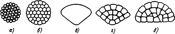
Fig.2. Cross-section of conductors of the cable:
a, b- round twisted stranded unconsolidated and compacted, c, d -
sector single-wire and multi-wire compacted, d- segment twisted stranded sealed
The most widely used cables are insulated with cable paper, less often with rubber insulation. Development chemical industry and mass production of electrically insulating plastics made it possible to develop and introduce cables with plastic insulation and sheaths (mainly 1-6 kV).
Paper insulation has good insulating properties, sufficient heat resistance (up to 80°C), a high degree of uniformity, and a relatively low cost. Its disadvantage is hygroscopicity, which makes it necessary to carefully protect the cable with waterproof sheaths and seal the end devices of the cable line (with terminations and couplings).
Paper insulation is made from special cable paper impregnated with an insulating compound, which usually includes mineral oils and rosin, and for cables with so-called non-draining compounds - ceresin, viscous mineral oil, rosin.
The conductors are insulated with spirally wound cable paper tapes 5-30 mm wide. The thickness of the layer depends on the rated voltage of the cable. The upper core insulation tapes, as a rule, are made in different colors: on one core - from ordinary cable paper, on the other - from red paper or from cable paper with a red stripe, on the third - from paper of any color (or with a stripe). In four-core cables, the top insulation tape of the zero core is made of ordinary cable paper.
Belt paper insulation is applied over insulated and twisted wires. At the same time, fillers from paper bundles are placed in the gaps between the cores.
Rubber insulation consists of rubber mixed with a number of components (fillers). Its advantages are flexibility and almost complete non-hygroscopicity, and its disadvantages are high cost, relatively low operating temperature of the conductors (up to 65 ° C), rapid aging under the influence of sunlight, etc. To determine the phases, the insulation of the conductors is made of multi-colored rubber or rubberized fabrics.
Plastic insulation is made of polyvinyl chloride or polyethylene. PVC-insulated cables are mainly manufactured for operating voltages up to 1 kV. The disadvantage of this insulation is its thermoplasticity, since the heating of the cable causes softening of the insulation, displacement of the cores and a decrease in electrical strength over time.
More promising is the use of polyethylene insulation, which has good mechanical and electrical insulating properties in a wide temperature range, resistance to acids, alkalis and moisture.
To improve the electrical characteristics of the insulation, some types of cables are equipped with screens that align and reduce tension. electric field in isolation. Screens are made of metallized paper, semi-conductive polyethylene, etc. In 6 kV cables with plastic insulation, the screens are applied over the insulation of the cores, and in cables of 10 kV and above, both over the phase insulation and on each core.
The electric field inside the cable is also leveled with the help of fillers - bundles of paper tapes or cable yarn, threads of polyethylene, polyvinyl chloride or rubber, which fill the gaps between the insulated cores.
Hermetic protective sheaths serve to protect the cable insulation from environmental influences, mainly from moisture penetration, and are made of lead, aluminum, plastics and rubber.
External protective covers consist of three main elements: cushion 5, armor 6 and outer protective layer 7 (see Fig. 1) and are applied to the cable sheath to protect it from mechanical damage.
The cushion protects the sheath from damage when armor is applied, as well as when the cable is bent during its laying. At the same time, the cushion protects the shell from chemical and electrochemical corrosion. Typically, the pad consists of several layers of bituminous composition, impregnated cable paper tapes and cable yarn and has a thickness of 1.5-2 mm.
The armor protects the cable sheath from mechanical damage and, depending on the allowable tensile forces, is made of steel tapes or flat (sometimes round) steel wires spirally wrapped around the sheath.
The outer protective layer protects the armor from corrosion and can be non-combustible and ordinary. The non-combustible protective layer is made of two layers of fire-resistant compound, glass yarn and chalk coating, which protects the coils of the cable on the drum from sticking, and the usual one is made of impregnated cable yarn (jute), two layers of bituminous composition and chalk coating.
Cables with plastic outer protective covers are also produced, which have a different design and are applied mainly to an aluminum sheath (for example, AASHv).
Cable marking. Cables are marked according to the material of the conductive cores of insulation, sheaths and the type of protective covers. The first letter in the cable marking indicates the material of the cores: A - for aluminum (for copper, the letter is not affixed); the second indicates the type of cable insulation: PVC. P - polyethylene. R - rubber (paper insulation is not indicated). This is followed by the designation of the shell material: A - aluminum, C - lead, B - polyvinyl chloride compound, P - polyethylene, P - self-extinguishing polyethylene, H - non-combustible oil-resistant rubber. The letters ST indicate that the sheath is made of steel corrugated tube.
The designations of the protective covers of the cable follow after the designation of the sheath: B - armor made of steel tapes with an outer protective layer, P and K - the same, made of flat or round steel wires.
For example. AAB - cable with aluminum conductors, paper insulation, in an aluminum sheath, armored with two steel mites, with an outer layer of jute; APVB - a cable with aluminum conductors, polyethylene insulation, sheathed with PVC compound, armored with two steel tapes with an outer layer of jute.
After designating the type of armor, there may be either letters deciphering the outer covers of the cable. At the same time, a protective cover of a conventional design and a pillow of a normal design are not indicated. If there is no jute protective layer on the cable, the letter G (bare) is affixed, for example, SBG, AAPG. A non-combustible outer protective layer is designated with a lowercase letter "n" (for example, ASBn), a reinforced protective coating of an aluminum shell - with the letter "v", and a particularly reinforced one - with the letter "y" (for example, AABv, AABu).
Cables with a plastic outer protective cover made of a PVC or polyethylene hose are marked with the letters Шв or Шп, after the designation of the sheath. For example, AASHv - a cable with aluminum conductors, impregnated paper insulation, in an aluminum sheath with a PVC hose; ААШп - the same, but with a hose made of polyethylene plastic.
Separately leaded cable cores are designated with the letter O (for example, AOSB or OSB). Depleted-impregnated insulation of cables intended for vertical laying is additionally denoted by the letter "B" (for example, ASB-V). If the paper insulation is impregnated with a ceresin-based non-draining compound, the letter "C" is placed before the cable marking (for example, TsAASH). The letters "ozh" placed at the end of the marking in brackets mean that the conductive core of the cable is solid single-profile, for example, AAB (ozh). The letter "b", located after the designation of the armor, indicates that there is no protective cover cushion (for example, AVBbShv), and the letters "c" and "p" indicate that the cushion is made of PVC or polyethylene hose, respectively (for example, AABv, ASBp). Reinforced and especially reinforced pillows are designated respectively by the indices "l" and "2l" (for example, AAB, ASB). Cables with paper insulation, which has increased heat resistance, have the letter "U" at the end of the marking.
The numbers following the letters in the marking indicate the rated operating voltage of the cable (kV), the number of conductive cores and their cross-sectional area (mm). For example, the cable ASB-S 3x120 mm is designed to operate at a voltage of 6 kV and has three cores with a cross section of 120 mm, and the cable APVB-1 3x50 + 1X25 mm - for laying in networks up to 1 kV, has three cores with a cross section of 50 mm and one with a section of 25 mm.
Cable packaging. Power cables manufactured at the factory are wound on cable drums in regular rows and covered with sheathing to protect against mechanical damage.
The drum type is chosen so that the diameter of its neck is at least 15-25 diameters of the wound cable. On the cheeks of the drum, indicate the manufacturer, brand and length of the cable, the number of cores and their cross section, voltage, gross and net weight, date of manufacture and number of the standard according to which the cable is made. Each reel with cable voltage of 6 kV and above is completed with a factory test report, which is put into a waterproof bag and attached to the inner surface of the reel under the casing. On drums with a three-core cable, the order of alternation of the cores of the ends of the cable is indicated: direct (letter B) or reverse (letter O).
Basic requirements for cable lines
Power cables are laid in the ground, water, as well as in outdoor structures, in tunnels, channels, blocks and inside buildings.
Cable inserts for overhead lines are laid mainly in trenches. On the territory of power plants and substations, cables are often laid in small closed channels. With a large number of cables, tunnels, passage channels are built, or blocks of pipes are laid. Cables in tunnels and channels are fixed on prefabricated metal structures shelves. In the open air, cables are laid only when the territory is highly saturated with underground utilities.
The depth of laying cables up to 10 kV in the ground should be 0.7 m, and at the intersections of streets, roads and railways - 1 m.
Reducing the cable laying depth to 0.5 m is allowed in sections up to 5 m long when entering the building, as well as at intersections with underground utilities, if the cables are protected from mechanical damage.
The bending radius of the cable at the turns of the route must be at least 15-25 of its diameters and depends on the material of the insulation and sheath, as well as the design of the cores. To avoid dripping of the impregnating composition, the level difference between the highest and lowest points of the cable route with impregnated paper insulation should not exceed 5-25 m, depending on the voltage. Cables with depleted insulation can be laid at height differences up to 100 m, and with non-drip impregnation and plastic insulation - at any level difference.
The input of cables into buildings or structures is carried out through segments of asbestos-cement or metal pipes. At the same time, the space between the pipe and the cable is clogged with tow mixed with gray impervious clay to prevent water from entering the building from the trench.
Cables laid indoors should not have external protective covers made of combustible fibrous substances. With mixed routes, when the same cables are laid in the ground and inside buildings, cables with an outer jute cover are used, and the jute cover is removed in areas inside buildings.
The exit of cables from the trench to the walls of buildings or VL supports is protected by pipes or boxes to a height of 2 m from the floor or ground.
Intersections with engineering structures they are carried out in steel or asbestos-cement pipes, the length of which at crossings over roads or railways is determined by the width of the right of way of the road.
When approaching (crossing) power cables with various engineering communications between them, the distances determined by the EMP must be maintained. When cable lines intersect, low voltage power cables are placed above high voltage cables. Parallel laying of cables above and below pipelines is not allowed. When crossing with communication cables, power cables are located below.
Near electrified railways, the destruction of the metal sheaths of cables by stray currents is possible. Therefore, the cable line route is located no closer than 10.75 m from the axis of the electrified railway and 3.25 m not electrified, and in cramped conditions they are protected from the dangerous influence of stray currents with special devices.
All laid cables, couplings and terminations must have tags indicating the brand, section and voltage of the cable, number or name of the line, as well as the date of installation. The best material for tags is plastic. Tags are installed in cable structures every 50 m, as well as at a distance of 100 mm from the neck of the coupling or termination, at the points of entry and exit of the cable from the channel, tunnel, well, on both sides of the interfloor overlap,
Before commissioning, the installed cable lines are tested. First, on all cables up to 10 kV, they check the integrity of the cores (no breaks), the condition of the insulation and the correct connection of each core to the phase of the same name at both ends of the cables (core phasing) with a 2.5 kV megohmmeter. Then they measure the insulation resistance of cables up to 1 kV, which should be at least 0.5 MΩ, and 6-10 kV cables are tested increased voltage rectified current, equal to six times the commemorative voltage of the cable,
The place of damage to a faulty cable is searched for with special devices. After that, the cable is repaired: they dig a trench at the site of damage, cut out the damaged piece and mount an insert (at least 8 m long) with two couplings.
The following documentation must be submitted for cables put into operation: a cable line project with changes and deviations made to it; executive route of the line; passports and protocols of factory tests of the cable; acts of acceptance for the installation of trenches and channels; acts of hidden works for laying cables and pipes; magazines for cable laying and installation of cable boxes; certificates of commissioning of the cable line.
The documentation must be signed by the foreman or foreman and the performer of the work - the foreman. The magazines for the installation of couplings and terminations are also signed by the electricians-cable workers who performed these works.
Laying cables in the ground
trench preparation. The cheapest and most common way to lay cables is to lay them directly in the ground in specially dug trenches. Prior to the start of trench digging, the cable line route is marked and laid out on the ground, for which pegs are hammered along the axis of the future trench after about 50 m. Particularly carefully break the corners of the route, taking into account the permissible bending radius of the cable. After the breakdown of the route, a permit for excavation is issued (in a populated area - an order). Then they call the owners of underground utilities crossing the route or passing near it, and in their presence they manually dig small transverse trenches (pits) to detect underground utilities. When following the cable route parallel to the communications, the pits are dug throughout the approach area every 5-10 m, and then they begin to dig a trench.
Cable trenches are usually dug with special excavators-trenchers. To develop trenches up to 1.2 m deep and 0.2-0.4 m wide, the ETTs-165 trencher is used. The ETR-134 bucket-wheel excavator opens trenches 0.3 m wide and up to 1.3 m deep. E-153 single-bucket excavators and ER-7A rotary excavators are also used. In places where it is impossible to use mechanisms due to the large number of underground communications, green spaces, cable trenches are dug manually.
Near the existing cables, trenches and pits are developed with particular care, and starting from a depth of 0.4 m - only with shovels. The use of crowbars and pickaxes is prohibited. If an unknown cable is discovered while digging a trench or a smell of gas appears, work is immediately suspended and workers are removed from the trench.
Under normal conditions, the depth of the trench (taking into account the thickness of the bed for the cable) should be 0.8 m - with a cable protection device against mechanical damage, or 1-1.2 m - without protection. It is allowed to develop trenches with vertical walls without fasteners, with a depth of not more than 1 m in bulk and sandy soils of natural moisture, 1.25 m - in sandy and clayey and 1.5 m - in clays. It is necessary to throw out the soil from the trench at a distance of at least 0.5 m from the edge so that it does not crumble back. In all cases, the cable should be laid immediately after digging the trench.
The soil on the route should not contain chemicals that destroy the armor and cable sheath. In areas where the soil is saturated with acids or consists of rotting organic matter, slag, the cable is laid in asbestos-cement pipes or the route is swept out of such areas.
Crossings through roads and railways, as a rule, perform in a hidden way(without digging a trench) using the IP-4603 pneumatic punch. The pneumatic punch is installed on guides according to the level in a pre-excavated pit. At the opposite end of the transition, a receiving pit is torn off. Under the action of compressed air supplied by the compressor, the hammer hammers the pneumatic punch into the ground. Since the soil is compacted by the walls of the pneumatic punch, the hole retains its round shape. After the pneumatic punch exits into the receiving pit, pipes are laid in the hole. The pneumatic punch is used when laying pipes with a diameter of up to 200 mm; pipes of large diameters are pressed in with a hydraulic jack.
When arranging road crossings in an open way, trenches are dug manually, in turn closing one and then the other half of the road for traffic. Pipes with wire are laid in the trench for the subsequent pulling of the cable. To prevent clogging of pipes, they are closed with wooden plugs.
The trench under the railway tracks is torn off when there are breaks in the train schedule. To maintain the strength of the path, a trench is dug only between two adjacent sleepers (for one "sleeper box"). For a wider trench, first one "sleeper box" is opened, pipes are laid in it, and then the adjacent one. After laying the pipes, the soil is carefully compacted, the ballast layer is restored and the rails and sleepers are cleaned.
Cable laying in a trench. Work on laying the cable in the trench consists of the following operations: transporting the drum with the cable to the trench; delivery and laying of bricks or reinforced concrete slabs along the trench; installing the drum on screw cable jacks, removing the drum sheathing and carefully inspecting the cable; bedding devices from shallow earth; unrolling the cable and laying it in a trench; drawing up an executive drawing; backfilling with soft earth or sand, laying bricks or slabs and backfilling the trench with soil; pointer settings.
For loading and unloading operations and transportation of cable drums, cranes and cars are used, as well as special vehicles- cable conveyors. In exceptional cases, cable drums are unloaded manually along inclined bars. Throwing drums from a car is strictly prohibited. The drums are transported along the route and installed on cable jacks so that the end of the cable of one drum extends beyond the beginning of the other by at least 3-4 m. cm and begin preparations for rolling out the cable.
The method of rolling depends on the complexity of the route. If there are no intersections with communications on the route, the cable is laid directly on the bottom of the trench from a cable conveyor moved along it by a car or tractor,
If there are intersections, the drum with the cable is installed on cable jacks and rolled out using a winch. To do this, the winch cable is unwound along the bottom of the trenches, dragged under the crossed communications and connected to the end of the cable. Support rollers are installed at the bottom of the trenches, and corner rollers are installed at the corners of the route. The winch cable is coupled to the end of the cable using a wire "stocking" or directly behind the conductive wires. A "stocking" is put on the end of the cable and firmly fixed with a wire bandage over a length of at least 0.5 m.
With the help of a winch, it is allowed to pull a cable of a relatively short length, since with pulling forces in excess of the permissible ones, a rupture of the sheath or cable cores may occur.
When pulling the cable through the pipes, detachable mounting funnels are installed, and the pipes themselves are pre-cleaned and lubricated with grease.
If it is impossible to mechanize the laying, the cable is unwound from the drum and laid in the trench by hand. Workers should be on one side of the cable and lay it on the commands of the work manager. It is possible to roll drums and roll out a cable only in mittens.
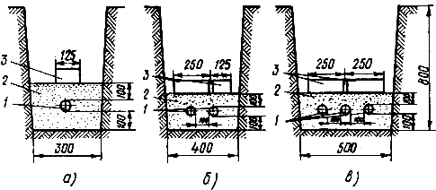
Fig.3. Gasket one ( a), two (b) and three (c) cables in trenches covered with bricks:
1 - cable, 2 - a layer of shallow earth, 3 - brick
When rolling out, it is necessary to monitor the bending radius of the cable and the speed of movement, for which they put an observer at the drum and arrange a brake, which regulates the speed of rotation of the drum.
Having finished rolling, the cable is removed from the rollers and laid in a trench with the so-called normal slack ("snake"), which compensates for the stretching when the cable is heated. In the places of installation of couplings, a margin is left in the form of half-loops.
After that, an executive drawing of the route is drawn up with reference to permanent landmarks, the cable is sprinkled with a layer of soft earth 10 cm thick and protected from mechanical damage. Cables 6-10 and 20-35 kV are closed along the entire length of the route, respectively, with red brick of grade 100-150 and reinforced concrete slabs, and up to 1 kV - with brick only in places of frequent excavations.
With one cable in a trench (Fig. 3, a), bricks 3 are laid in one row along the route over a layer of soft earth. To protect two cables, two rows of bricks are required: one - along, and the other - across the route (Fig. 3, b). Three cables are protected by two rows of bricks located across the route (Fig. 3, c).
It is allowed to lay cables up to 20 kV without protection. In this case, the depth of their laying should be within 1-1.2 m.
Instead of protecting the cable, sometimes a warning bright plastic tape is laid along the route at a depth of 0.5-0.6 m.
On top of bricks or slabs, a trench with a cable is covered with excavated soil, which is laid in layers no more than 20 cm thick, carefully compacting and ramming each layer. If the excavated earth contains construction garbage, slag, stones, use imported soil or sand. AT winter time the trench must be covered with thawed soil.
The trench is finally leveled and the track is cleaned with a bulldozer.
Laying cables in blocks, pipes and structures
Laying cables in blocks and pipes begins with checking the depth, straightness, cleanliness and tolerability of channels and pipes. The depth of the blocks should correspond to the project, the diameter of the holes in the reinforced concrete blocks should be at least 90, and the diameter of the pipes should be at least 50 mm with a pipe sewerage length of up to 5 m and at least 100 mm with a longer length. As a rule, the diameter of the pipes should be within 1.5-2 of the outer diameters of the cable. The minimum dimensions of cable well hatches and the slope of cable blocks to ensure water flow have also been standardized.
Particular attention is paid to inspections of wells and checking the absence of explosive and poisonous gases in them. Inspections are carried out by a team of two electricians under the supervision of the work manager for work permits of the operating organization. At the same time, one of the workers is tied with a rope and descends into the well, and the second secures him from the outside at the open hatch. To avoid explosions, it is not allowed to smoke, light matches and use open flames in the wells.
The straightness of the laying of blocks and pipes is checked using an electric lamp or other light source, and cleanliness and tolerance are checked with a control cylinder with steel ruffs, the diameter of which must correspond to the inner diameter of the holes of the blocks and pipes. Steel wire is preliminarily pulled into the channels and with its help an auxiliary rope is pulled through the pipes, to the end of which a control cylinder and a traction rope are attached for laying the cable. Sometimes the wire is pulled into the channels during the construction of cable ducts. With a pipe length of up to 50 m, the wire is passed through the channels manually, and with a longer one - with a special pneumatic device.
The laying of cables in blocks is carried out mainly in a mechanized way, alternately tightening them into the holes of the blocks in the area between two adjacent wells. It is also possible through cable laying through several wells without a cut. However, the tensile forces in this case should not exceed the maximum allowable. After the end of the broach, a reserve (slack) of the cable must be created for laying it on supporting structures in intermediate wells.
Before laying cables in wells 3
(Fig. 4) corner rollers are installed in them 4
and detachable funnels 5, and the steel rope 8,
preloaded into the canal 6
cable block, attached to the sheath or cores. To control the pulling force, a dynamometer or other control device is mounted on the traction winch. 9.
The maximum allowable tensile force for cables of various brands and sections is determined from the tables. To reduce the tensile force, the surface of the cable is coated with a lubricant (for example, grease).
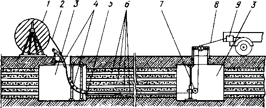
Fig.4. Cable laying in blocks:
1 - cable drum, 2 - cable, 3 - manhole, 4 - corner rollers, 5 - detachable funnel, 6 - cable block channels, 7 - rope roller, 8 - rope, 9 - pull force control devices
During the tightening of the cable, it is continuously monitored for its passage along the rollers in the wells and the exit from the drum. Laying is carried out at a speed of 0.6-1 km / h, if possible without stops.
Couplings placed in the wells, after installation, are closed with detachable protective fire covers. The ends of pipes and openings of blocks at the entrances to buildings and structures are sealed with fireproof, easily destructible material.
Cables are laid in pipes mainly when crossing any obstacles, for example highways. Since the length of the cable transition is usually small and there are no cable wells, the cable can be laid both mechanically and manually. Couplings are placed outside the pipes.
When laying cables along supporting structures outside and inside buildings and structures, cable shelves or brackets on straight horizontal sections are placed at intervals of 0.8-1.0 m. At the turning points, this distance depends on the mass of the cable and its permissible bending radius. On vertical routes, the distance between the brackets is determined by calculation and indicated in the projects, and in the absence of such instructions, it is assumed to be 1-2 m. To pass through partitions, walls and interfloor ceilings, nozzles from asbestos-cement and other fireproof pipes are installed. Metal support structures and protective coatings, as well as steel pipes, are grounded.
The laying of cables along the structures is carried out both mechanically and manually. Heavy cables of great length are laid with a winch. The cable drum is mounted on jacks and rolled out with a winch along linear and angular rollers fixed on the structures. Lightweight short cables are unwound by hand, and then transferred and laid on structures. After laying, the cables are rigidly fixed: in horizontal sections - at the end points, at the angles of rotation, on both sides of the compensators and at the connecting and end sleeves, and on the vertical sections - in the places determined by calculation. Between metal support structures and unarmored cables in a lead or aluminum sheath, elastic gaskets made of non-combustible material (for example, asbestos, polyvinyl chloride) with a thickness of at least 2 mm are laid, and an anti-corrosion coating is applied to the metal armor of the cables.
Branch pipes and openings for the passage of cables through the walls are sealed with fireproof, easily destructible material. In this case, the cables are pre-wrapped with a tape of fireproof material. Couplings are protected by casings and additionally separated from the upper and lower rows of cables by asbestos-cement partitions.
Inside the production premises, it is allowed to lay armored (without a combustible outer cover) and unarmoured (with a non-combustible sheath) cables. In places accessible not only to operating personnel, but also to unauthorized persons, the cable is protected from mechanical damage by steel angles, casings or tubes to a height of m.
When laying cables with voltage up to 1 kV on unplastered wooden walls and other surfaces made of combustible materials, remote brackets are installed so that the clearance between the cable and the wall is at least 50 mm.
Laying cables along trays and overpasses does not differ from their laying along supporting structures.
On bridges with heavy traffic, cables are laid in an aluminum sheath, which has an increased resistance to vibrations. On metal and reinforced concrete bridges, cables are laid in asbestos-cement pipes, and on wooden ones - in metal pipes; while the distance between metal pipe and bridge structures should be 50 mm. Laying cables on bridges is similar to laying them in pipes, only at the points of transition through the expansion joints of bridges it is necessary to arrange expansion joints in the form of a cable half-loop.
Cabling under special conditions
Laying cables at low temperatures requires the development of trenches in frozen soils, for which they use ETTs-165 trenchers equipped with a special working body (bar), or two-bar tracked BR machines. Frozen soils are loosened with pneumatic jackhammers. Besides, different ways warm up the soil.
In winter, laying is usually performed by preheating the cable. Depending on the type of insulation and the protective cover of the cables, limiting negative temperatures are established at which it is possible to unwind them without heating. So, cables up to 35 kV with paper insulation can be laid without heating, if the air temperature during the day before laying was not lower than 0°C. For cables with rubber insulation and a protective cover, this temperature should not be lower than -7 ° C, with plastic insulation and sheath - not lower than -20 ° C. Short-term drops in temperature for 2-3 hours (night frosts) are not taken into account.
Warm up cables in several ways. When heating with current, special step-down transformers TSPC or conventional welding ones are used. The drum is pre-insulated with a felt-tarpaulin hood, the ends of the cable are cut and the cores on one of them are connected to each other (short-circuited) and on the other they are connected to the output terminals of the transformer.
The temperature of the outer turns of the cable is controlled by a thermometer, and the current is controlled by current clamps. Maximum admissible current determined from the tables and adjusted by rearranging the plates on the terminals secondary winding transformer. The warm-up time depends on the air temperature, cable section and current and ranges from 1 to 3 hours. primary winding transformer should be no more than 250 V in relation to the ground. Metal sheaths and armor of cables and housings of transformers and welding machines grounded securely.
In the absence of power supply sources, the cables on the drums are heated by heat blowers with internal combustion engines.
After warming up, the cable must be rolled out and laid in a trench as soon as possible (no more than 1 hour, 40 and 30 minutes, respectively, at temperatures from 0 to -10 ° C, from -10 to -20 ° C and -20 ° C and below ).
Cable laying in permafrost conditions is limited by the risk of damage due to soil deformations (heaving, precipitation, frost cracks, thermokarst phenomena, etc.). In addition, during operation, the cables themselves become sources of heat, which leads to a violation thermal regime frozen ground. Therefore, above-ground laying of cables along various supporting structures is more reliable: the walls of buildings, structures and insulated boxes for laying heating networks, water supply and sewerage; under pedestrian decks; overpasses or in special reinforced concrete trays.
If above-ground laying is not possible, the cables are laid in a trench dug in permafrost soil (Fig. 5). To increase the reliability of the line, it is recommended to use cables with wire armor. The depth of the trench should be 15-20 cm below the level of the layer subject to seasonal freezing and thawing, but not less than 0.9 m. h which depends on the layer thickness. The soil for the embankment is taken from places remote from the trench at a distance of at least 5 m. When backfilling the trench, the soil is carefully crushed and compacted. Boards are used to protect cables from mechanical damage. At intersections with structures, cables are covered with steel sheets or reinforced concrete slabs. Pipes at crossings can only be used in well-draining soils; the slope must be at least 5%.
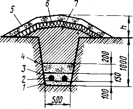
Fig.5. Cable laying in permafrost:
1, 3
- sand, 2
- cable, 4
- gravel or rubble, 5
- drainage soil, 6 - peat, 7 - local soil
When laying cables along overhead line supports or walls of buildings, they are protected with angle steel or special boxes.
The rolling and laying of cables in permafrost soils is carried out in the same way, using the same mechanisms and devices as in normal conditions. However, they must be laid with a margin increased by 3-4% in length (increased "snake") in order to reduce the likelihood of damage during soil movement.
When laying cables under water (when crossing rivers, canals and other water barriers), they are buried at least 1 m into the bottom. At the exit from the water, the cables are laid in pipes. On each bank, a reserve of cable with a length of at least 10 m (half-loop) is created. When laying several cables in parallel, the distance between them must be at least 0.25 m. Crossing of cable lines under water is not allowed.
For underwater laying without pipes, lead-sheathed cables with wire armor and an external protective anti-corrosion coating are used. When crossing small, non-navigable and non-alloyable rivers, it is allowed to use cables with tape armor.
Mechanized laying of cables through water bodies can be carried out with two winches installed on opposite banks, from a barge, a towed winch, or self-propelled, from a self-propelled vessel, as well as from ice, the thickness of which should be at least 25-30 cm. The laying speed in all cases should be no more than 12m/min. At low temperatures, the cables are heated before laying.
Laying AAS cables is allowed only on simple routes with a minimum number of turns and transitions, since the PVC hose sheath has relatively low mechanical strength and is easily damaged during installation, which leads to accelerated corrosion of the aluminum sheath and insulation breakdown.
The laying of these cables in pipes is allowed only on straight sections of the route no more than 40 m long and at the entrances to buildings and structures. For each cable line, no more than three transitions in pipes with a total length of not more than 40 m are allowed, the length of one transition should not exceed 20 m. The inner diameter of the pipes is chosen so that it is at least two outer diameters of the cable.
Laying is recommended to be done mechanically. To protect the PVC hose from mechanical damage (seizures, punctures, breaks), the cable should not be allowed to touch the surface of the ground, floor, walls and structures. Before laying the route, the route is carefully prepared: the soil for the pillow and cable powder is cleaned of fine gravel, broken glass, etc .; sharp corners, edges and protrusions of all supporting cable structures are rounded off; in places where the cable passes through walls and partitions, pieces of plastic pipes are installed.
Before laying at low temperatures, the cable must be warmed up. It is not allowed to lay (and rewind) cables at temperatures below -20 and above +30°C.
After laying the cable, the PVC hose is carefully inspected and repaired using a PS-1 gas-air or welding gun, welding small punctures, holes and shells with a stream of hot air. As an additive, a polyvinyl chloride rod is used. For large gaps, patches or split cuffs made of polyvinyl chloride tubes are welded.
Basic information about connecting and terminating cables
Connect the ends of the cables to each other and attach them to the inputs of electrical receivers with cable glands. Depending on the purpose of the coupling, it is divided into connecting (C), branch (O), stop (St) and end (K). In turn, end couplings can be for outdoor and indoor installation (KN and KB), as well as mast (KM). Terminations for indoor installation are also called terminations. According to the type of material from which the coupling bodies are made, they are divided into cast iron (Ch), lead (C), brass (L), epoxy (E), steel (St) and plastic (P). The dimensions of the couplings depend on the cross-section of the current-carrying conductors and the operating voltage of the cables.
The use of cable sleeves and terminations depends on the conditions of their operation: location (in the ground, in the air), ambient temperature, humidity, fire hazard of the premises, the presence of chemical active environment etc. The design of the coupling or termination is selected depending on the specific operating conditions in accordance with the technical documentation.
Mount cable glands only at the place of their installation, so all necessary materials are selected in advance, placed in one package and delivered to the installation site as a complete set. This procedure ensures compliance with the installation technology, high quality of work and reliability of the coupling.
When mounting couplings, materials are used according to a strictly limited list.
Casting compositions are used to fill the internal volumes of couplings and increase their electrical strength and tightness.
Couplings with voltage up to 10 kV are filled with bituminous compositions MB-70/60 and MB-90/75, having a softening temperature of 60 and 75°C, respectively. The composition MB-90/75 is poured into couplings mounted in heated rooms, and MB-70/60 couplings installed outdoors, in the ground and in unheated rooms at a temperature not lower than -10°C. Couplings operating at lower temperatures (down to -35°C) are filled with frost-resistant MBM composition, which consists of bitumen with the addition of transformer oil.
The disadvantage of bituminous compositions is their shrinkage during cooling after pouring and the formation of voids and cracks. Oil-rosin composition MK-45, which is used to fill couplings for voltages of 20 and 35 kV, as well as rosin-furfural frost-resistant composition KFM, designed for temperatures up to -50 ° C, is characterized by less shrinkage.
For washing (scalding) the junctions or terminating the cores, as well as for feeding the paper insulation, the MP-1 scalding mass is used, which is close in its characteristics to the impregnating composition for cable paper.
Rollers and rolls are used to insulate the junctions of the cores of cables with paper insulation. They are made from cable paper with a width of 5 to 50 mm (rollers) and from 50 to 300 mm (rolls), dried in a vacuum, impregnated with an oil-rosin composition and placed in cans, which are poured with a scalding compound and sealed. Each can is packed with a standard set of rollers and rolls, which is necessary for the installation of couplings of a certain type. The numbers of the sets and their purpose are indicated on the bank.
Insulating tapes are used not only to enhance the electrical strength of cable insulation, but also to ensure, under certain conditions, the tightness and mechanical strength of cable boxes and terminations.
Depending on the type of couplings, cotton (taffeta or taffeta) tape, sticky rubberized, polyvinyl chloride PVC (sticky or non-sticky) of various thicknesses, glass tape, oil-resistant varnished cloth and rubber tape are used.
Resin tape is also used to seal cables in the necks of connecting cast-iron couplings and end funnels. When soldering and welding cores, asbestos tapes are used to protect insulation from open fire.
As a rule, mites are supplied wound in circles of various diameters.
Varnishes and enamels are used to protect the metal parts of couplings from corrosion, as well as insulating and adhesive compounds (when installing end fittings). Varnishes are solutions of film-forming substances (resin, bitumen, etc.) in volatile solvents (xylene, white spirit, acetone, etc.). To obtain enamels, dyes are added to the varnish (red iron, zinc and titanium white, etc.).
For anti-corrosion coating of coupling bodies, as well as cast iron and steel casings, BT-577 bituminous varnish, GF-92XS glyptal enamel and KhV-124 perchlorovinyl enamel are used.
When mounting end fittings, mainly varnish GF-95, coating and filling compounds based on dichloroethane (for embedding from PVC tape) and enamel GF-92HS (for embedding and end sleeves made of epoxy compound) are used.
Solders and fluxes are used for tinning the joints and terminations of the cores, as well as for soldering shells and ground wires. According to the melting temperature, solders are conditionally divided into soft (up to 400°C) and hard (400°C and above). For tinning aluminum cores and cable sheaths and their soldering, aluminum solder A is used. When copper is connected to aluminum, zinc-tin solder TsO-12 with a high zinc content is used. Soldering of copper conductors and soldering copper wires grounding to steel armor and lead sheath is performed with tin-lead solders POS40 or POSSU30, POSSU40 (with the addition of antimony).
Fluxes contribute to a uniform and strong connection of the solder to the base metal. Soldering fat, consisting of rosin, stearic acid, zinc chloride and other components, as well as technical stearin and pine rosin, are most often used as fluxes when soldering copper conductors, lead sleeves and ground wires.
Epoxy compounds used for pouring sleeves and seals are obtained by mixing various epoxy resins with other components (plasticizer, filler and solvent). These compounds are a thick pasty mass, which turns into a solid state, forming monolithic products with slight shrinkage. They have good adhesion to metals, high electrical and mechanical strength, water resistance and oil resistance.
Before use, the compound is thoroughly mixed and a hardener is added, after which, depending on the ambient temperature, it is suitable for use within 0.5-3 hours. One of the disadvantages of compounds is that their normal polymerization requires a temperature of at least +5 ° C . At lower temperatures, it is necessary to arrange external heating of the sleeve to be poured up to 20-25°C for several hours.
Epoxy compounds K-176, K-115 and UP-5-199 are used for the installation of couplings and terminations with voltage up to 35 kV. It is allowed to use the E-2200 compound manufactured by the Czechoslovak company Hemapol. Compounds are supplied ready-to-use in hermetically sealed cans and are usually included in standard kits for mounting couplings.
In addition, when mounting couplings, thermite cartridges, connecting sleeves, cable lugs, copper flexible wire, technical vaseline, paraffin, asbestos cord and other auxiliary materials and products.
Cable termination
The connection and termination of cables in couplings of any design begins with the cutting of their ends, which consists in the sequential removal of factory covers in stages. The length of the entire cut and individual steps is determined by the design of the coupling, the cross section and voltage of the cables:
Beforehand, the ends of the cables to be connected are carefully straightened and overlapped, and when installing the terminations and terminations, they are laid to the place of their installation, observing the permissible bending radii. The ends of the cable are carefully inspected, the integrity of the sealed sheath is checked, and then a piece of cable is cut off at least 150 mm long and the paper insulation is checked for moisture.
To do this, the filler and paper tapes adjacent to the core and the sheath are removed and immersed in paraffin heated to 150 ° C. The presence of moisture is determined by slight crackling and foaming on the tapes. With wet insulation, a piece 1 m long is cut off from the test end of the cable and the test is repeated. The operation is repeated until the check shows the complete absence of moisture. Wet cable ends must not be connected or terminated.
Cutting the cable begins with the removal of the outer cover (Fig. 6), for which at the place of cut it is at a distance BUT put on a wire bandage. Then the outer cover is unwound from the end of the cable to the bandage, bent and used later to protect the armor and aluminum sheath from corrosion. The second wire bandage is applied to the armor at a distance B from the first, cut the armor along the edge of the bandage so as not to damage the lead (aluminum) sheath of the cable, and remove it.
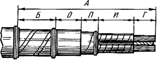
Fig.6. Cutting the end of a three-core cable with paper insulation
Next, cut off the inner cushion and remove the layers of protective paper from the metal sheath, preliminarily slightly heating them with a blowtorch, and clean the surface of the aluminum (lead) sheath of the cable with a rag soaked in gasoline.
The lead (aluminum) sheath is removed after preliminary marking and applying two annular and two longitudinal cuts. The first annular incision is made at a distance O from the cut of the armor, the second - at a distance P from the first. Longitudinal cuts are made from the second annular cut to the end of the cable at a distance of 10 mm from one another. The sheath strip between the longitudinal cuts is grasped with pliers and removed, after which the rest of the sheath is removed. The annular (safety) belt on the lead (aluminum) sheath is removed immediately before the termination of the end into the coupling.
After removing the shell, the belt insulation is removed, as well as the filler. The insulation is unwound in separate mites, breaking off at the left annular belt on the lead (aluminum) sheath. Then the cable cores are pulled apart and smoothly bent using a special template. In the absence of a template, the cores are bent manually, preventing fractures and damage to the paper insulation. Finishing cutting, measure the distance AND, impose a bandage of harsh threads and remove the paper tapes of phase insulation in section G, the length of which depends on the method of connecting or terminating the cores.
The procedure for cutting cables with plastic insulation is the same as with paper. The outer jute cover or PVC hose, aluminum sheath (or armor and cushion under the armor - for cables with protective covers), hose, screen, semi-conductive coatings and core insulation are sequentially removed from the cable, the cores are bred and bent using templates or manually. Further operations consist in connecting or terminating the cores, restoring the insulation and sealing the junction (terminating). They are performed according to the technology established for each type of coupling.
Connecting cables
Connect cables using cast iron, lead and epoxy splices, as well as splices with self-adhesive tape and heat shrink tubes.
Cast iron couplings SCh and SChm (small-sized) are used to connect three- and four-core cables up to 1 kV with paper and plastic insulation. Conductive wires connected and insulated in an appropriate way are placed in the coupling body (Fig. 7). The cores are fixed at a certain distance from each other and from the body using porcelain spacers. 4
or insulating winding (in small-sized ones). The internal cavity of the body, together with the connected cores, is filled with MB-70/60 or MB-90/75 bituminous compounds. The main disadvantage of cast-iron couplings is their incomplete tightness, the possibility of moisture penetrating to the cable cores through voids and cracks in bituminous compositions, as well as along the cable between the armor and the lead sheath.
Cast iron couplings are mounted in this sequence. After cutting the ends of the cables, the conductive cores are carefully bred, bent and inserted into the holes of the spacer plates or fastened to them with bandages made of taffeta or keeper tape, welded in the MP-1 scalding compound. Spacers are installed on the insulated part of the cores, one on each side of the junction. The ends of the conductive wires are inserted into the sleeves 13
and connect by crimping or soldering, after which the lead (aluminum) sheath is removed between the annular cuts and the belt insulation is tied up at the cut point with a harsh thread. Then one end of the ground conductor 8
soldered to the sheath and armor of the cables, and the other is attached with a tip 10
to the clutch housing.
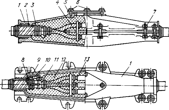
Fig.7. Pig-iron coupling MF for a three-core cable with voltage up to 1 kV:
1, 9 - upper and lower coupling halves, 2 - resin tape winding, 3 - P wire bandage, 4 - porcelain spacer, 5, 6 - cover and its bolts, 7 - tightening bolt, 8 - ground wire, 10 - tip, 11 - cable, 12 - bituminous composition, 13 - connecting sleeve
The connected cores are laid in the lower half-coupling 9 and seal the exit points of the cables from the necks with a layer of resin tape 2. After checking the correct arrangement of the cores, the upper coupling half 1 with a sealing gasket is applied to the lower one and tightened with bolts. Then the coupling is poured, in three or four steps, with a heated bituminous composition 12 (pre-heating the case to 60-70 ° C with a blowtorch). After cooling the coupling, the filling hole is closed with a lid. 5, fixing it with bolts 6. To increase the tightness of the coupling, the joints, necks, bolts and cover are poured with hot bituminous composition. When installed open, the coupling is coated on the outside with black asphalt varnish.
The coupling is marked with plastic tags, which are attached with galvanized steel wire and wrapped with two or three layers of tarred mite.
After "binding" the couplings to permanent landmarks (drawing the locations on the drawing) and laying the compensators in the form of half-rings of cable on both sides, they are covered with sand or soft soil. At the same time, the soil is carefully knocked under the couplings in such a way that its subsidence, and, consequently, the violation of the position of the couplings, are excluded.
Branch cast-iron couplings OC (T-shaped), OC (U - shaped) and OC (cruciform) are used in cable networks with voltage up to 1 kV for inputs to low-rise buildings. The disadvantages of these couplings are significant size and weight, the complexity of manufacturing and installation, as well as many standard sizes for combining cables of various sections and brands.
Three-core cables with an aluminum sheath used as a neutral wire are connected in cast-iron couplings. At the same time, jumpers for connecting shells are made of copper stranded wires with a cross section of at least half of the cross-sectional area of the phase conductors and are laid inside the coupling on spacers.
CC lead sleeves (Fig. 8) are used to connect 6-10 kV cables with paper insulation. These couplings have a higher tightness and electrical strength than cast iron, are quite reliable in operation and are widely used in cable networks. Sometimes lead sleeves are used to connect cables with plastic insulation.
Frame 3 coupling is a lead pipe, the ends of which are bent until they come into contact with the aluminum or lead sheath of the cables to be connected and soldered to them. Connected and insulated cores will be placed inside the pipe 10, filled with bituminous or oil-rosin filling compound 11. The coupling is protected from mechanical damage by a steel, fiberglass or cast-iron casing of hermetic (KzChG) or non-hermetic (KzCh) execution.
For different cross-sections of cores and cable voltages, lead couplings of six standard sizes are produced: from SS-60 to SS-110 (the numbers indicate the outer diameter of the pipe in mm).
Installation of a lead sleeve begins with cutting the ends of the cables and checking the insulation for moisture. The lead pipe is pushed onto one of the ends outside the cut. Pre-straighten the pipe and wipe its inner surface with a dry, clean cloth. The cores are bent, the insulation layer is removed stepwise from the ends and connected by soldering (in sleeves 9 or shapes) or by welding.
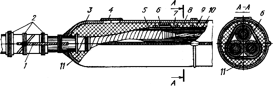
Fig.8. CC lead connector for 6-10 kV cables:
1 - grounding conductor, 2 - wire bandage, 3 - lead body 4 - sealed filling hole, 5 - winding rolls,
6 - a bandage made of rollers 25 mm wide, 7, 8 - winding rollers 10 and 5 mm wide, 9 - connecting sleeve, 10 - core, 11 - bituminous composition
The junctions of the cores are insulated with cable rollers 7 and rolls 5 and washed with a heated scalding composition MP-1. Then the veins are brought close together, bandages are wound around them 6 from rollers 25-50 mm wide, remove the protective annular belts of the shells, push the lead pipe over the junction and bend its edges so that even hemispheres without folds are formed at both ends, tightly adhering to the cable shells. The coupling body is carefully soldered on both sides to the cable sheaths, filling holes are cut in its upper part 4 and filled with heated bituminous or oil rosin composition. As the composition shrinks and cools, the coupling is topped up, and then the holes are sealed. The grounding conductor 1 is soldered to the middle of the body, sheath and armor of the connected cables.
Before laying in a cast-iron casing, a lead sleeve, a grounding conductor, bare areas of the armor and cable sheath are covered with a heated casting compound, and several layers of resin tape are wound on the cable on both sides of the sleeve. The coupling is placed in the lower half of the casing so that the winding coincides with the mouths of the casing. Then the coupling is closed with the upper half of the casing, tightening the bolts, and dousing it with a heated casting compound.
Backfilling with soil of a lead coupling is carried out in the same way as a cast-iron one. Lead couplings located in the open air (overpasses, cable structures) are protected by steel casings with asbestos coating.
Epoxy couplings are used for connecting and branching cables up to 10 kV with paper and plastic insulation, laid in the ground, tunnels, channels, etc. Couplings are manufactured and supplied in sets with all necessary materials.
An epoxy sleeve is a factory-made epoxy housing, inside which, during installation, cut and connected cores are laid and filled with an epoxy compound. After curing, the compound fixes the cores at a certain distance and isolates them from each other and from the coupling body.
For cables up to 1 kV with paper insulation, SES couplings with a removable housing (form) made of metal or plastic and SEM with lead cuffs, a cylindrical epoxy housing and two conical bushings (for connecting cables with single-wire solid conductors) are used. Power cables 6-10 kV with paper insulation are connected by epoxy couplings SEP and SEV, the epoxy cases of which have a transverse and longitudinal connector, respectively. To ensure electrical isolation distances, all couplings have three- or four-beam spacers cast in epoxy.
The technology for mounting epoxy couplings of all types is approximately the same. Cutting the ends and connecting the cores of the cables in them is carried out in the same way as in cast iron and lead. Coupling housings with a transverse split are preliminarily put on the ends of the cables. A grounding conductor with PVC insulation is soldered to the armor and sheath of the cables to be connected.
During cutting, the armor steps and sheaths of cables are stripped and wrapped with two layers of glass tape, smearing them with an epoxy compound. The same winding is performed on the bare parts of the cores. The paper insulation of the cores is preliminarily degreased with acetone or gasoline. Spacers are installed on the isolated sections of the cores, the half-couplings of the body are shifted, the cable entry points are sealed with resin tape and the coupling is filled with an epoxy compound.
Remove removable plastic or metal molds after curing of the compound (after about 12 hours at an ambient temperature of about 20°C).
To connect cables up to 1 kV with plastic insulation, PSsl couplings with self-adhesive LETSAR leps and heat-shrinkable tubes are used.
Cable termination
End fittings. The design of the termination depends both on the brand of the cable and on the operating conditions (air humidity, presence of conductive dust, chemical activity of the medium). A variety of conditions led to a numerous range of seals: in steel funnels, in lead, rubber and polyethylene (heat-shrinkable) gloves, from PVC and self-adhesive tapes, epoxy compound, etc.
Fig.9. Termination of 6-10 kV cables in a steel funnel:
1 - casting compound, 2 - winding the cores with PVC tape, 3 - porcelain bushings, 4 - cover, 5 - steel funnel, 6 - grounding bracket, 7 - funnel sprinkling half clamp, 8 - winding with resin tape, 9 - ground wire
End fittings in KVB steel funnels (Fig. 9) are used for terminating cables with voltage up to 10 kV inside dry and wet rooms. They are round or oval funnel 5 sheet steel with lid 4. Inside the funnel, cut and insulated conductive wires are placed. To increase the electrical strength, porcelain bushings are installed on the cores of 6-10 kV cables at the point of their exit from the funnel 3.
Installation of the KVB termination begins with cutting the cable, after which a funnel is put on its end, the cores are bred, and they are insulated with PVC or lacquer tape 2, install porcelain bushings and fill the funnel with a filling (bituminous) compound, after winding a resin tape around its neck 8. Tips are soldered to the ends of the veins, the funnel is grounded and fixed to the structure.
Terminations in lead gloves KVS (Fig. 10) are used for terminating three-core power cables with voltage up to 10 kV indoors, as well as in outdoor installations, provided that they are fully protected from direct precipitation and dust. Glove 3 is a lead cap with three lead fingers, which is put on the cut end of the cable. Previously, the cores 5 of the cable are additionally wound up with varnished fabric tape and coated with zapon-glyptal varnish.
Fig.10. Lead Gloved Cable Termination:
1 - sheath cables, 2 ground conductor, 3 - lead glove 4 - casting composition, 5 - cable core wound with tape,
6, 7 - leveling and surface winding, 8 - twisted twine bandage
For reliable sealing, the lower part of the glove is soldered to the lead (aluminum) sheath of the cable, and the upper part (i.e. fingers) is crimped around the cores into a cone. The places where the cores come out of the fingers of the glove and enter them into the tips are additionally wrapped with varnished fabric tape and sealed with a special winding 8 from twisted twine. Pre-soldered or pressed tips on the cores. The inner cavity of the glove is filled with the filling compound MB-70/60 or MBM. A grounding conductor 2 is soldered to the shell and steel armor.
Unlike embeddings in steel funnels, embeddings in lead gloves can be fixed in any position: vertically - with fingers up or down, horizontally or in any other intermediate position.
Terminations in rubber gloves KVR and KVRZ are designed for terminating power cables with a voltage of 1 and 6 kV, respectively, indoors. To seal the cores, tubes are glued to the fingers of rubber gloves. In the lower part, the glove is glued to the cable sheath and sealed with a clamp. The upper part of the tubes is glued onto the cylindrical part of the tip and clamped with a clamp or copper wire. Cable cores are pre-wound with any electrical insulating tape. Gloves and tubes are made from nairite rubber.
End seals made of self-adhesive tapes KVsl are mounted on cables up to 10 kV with paper insulation inside dry rooms with a level difference between the highest and lowest points of the cable route of no more than 10 m. The end of the cable is preliminarily straightened and cut, lugs are fixed on the ends of the cores and soldered to the armor and shell grounding conductor. Then, a thin layer of organosilicon varnish is applied to the cylindrical part of the lugs and the cable armor, and two layers of LETSAR tape are wound around the cores, while restoring the insulation at the place where the lugs are attached. After that, sealing cones are made from the LETSAR tape, varnished, inserted into the center of the groove and between the cores, sealed together with the cores and armor with a sealing winding from the LETSAR tape and covered with a layer of adhesive PVC tape.
Terminations made of KVE epoxy compounds are widely used for terminating power cables up to 10 kV indoors of all kinds (dry, wet, damp, hot, etc.) and outdoors with protection from rain and dust. KVE terminations have high mechanical and electrical strength, tightness, chemical resistance and can be installed in any position. Depending on the operating conditions, seals with various tubes are used: KVEN - made of nairite rubber; KVEtv - with heat-shrinkable PVC; KVEK - with organosilicon; KVET - with three-layer (a layer of polyethylene coated on both sides with polyvinyl chloride). In damp rooms, KVEP terminations are used.
Installation of terminations of all types of PVE is approximately the same. Tubes are put on the cut ends of the cables so that their lower parts are inside the epoxy housing. A form (funnel) is installed on the spine of the cable termination and filled with an epoxy compound. During the installation of terminations, it is necessary to maintain the air temperature at least 5 ° C and work with rubber gloves.
End fittings made of adhesive tapes PKV are used for terminating cables up to 10 kV with plastic insulation inside dry rooms. On cables up to 1 kV, PKV is terminated from several layers of PVC tape at the core wiring. For 6 kV cables, the metal screens of the cores are bent and grounded together with the armor, and the spine of the cutting is wound up with PVC tape. In terminations of 10 kV cables on cut cores, a conical winding is made of PVC tape, on top of which semi-conductive and metal screens are placed. The ground conductor is soldered to the metal screen.
In damp rooms for cables with plastic insulation, end seals with an epoxy compound casing are used to protect against moisture penetration into the space between the cores.
Outdoor Terminations. To terminate cables in places of cable inserts on overhead lines and approaches to transformer substations, three- and four-wire metal couplings for outdoor installation are used. These couplings are mounted on the end supports of the overhead line, open switchgears transformer substations and etc.
To connect cable lines to 1, 6 and 10 kV overhead lines, KM mast couplings are used. They consist of a cast iron (KMCh) or aluminum (KMA) body, in which porcelain bushings with conductive rods are fixed, a cover with a hole for pouring the mass, a brass cone and a lead cuff soldered to the cone. The sleeve is put on the cut end of the cable, the cores of which are connected with lugs to the conductive rods of the insulators. Then the lead cuff is soldered to the cable sheath and the inner cavity of the coupling is filled with bituminous compound MB-70/60 or MBM.
KN terminations (Fig. 11) with vertical outlets are used for terminating 6-10 kV cables with paper insulation in outdoor installations - open switchgears of substations. The KN coupling is similar in design to the KM mast couplings. However, in the KN coupling, porcelain insulators 7 are installed on the body 1 not obliquely downwards, but vertically upwards, which provides better sealing and greater reliability.
The KNE epoxy termination is more advanced than the KN termination. It consists of a housing and three bushings cast from an epoxy compound, does not require cast iron and porcelain insulators, is easier to manufacture and less laborious during installation. epoxy compound. After curing the compound, a monolithic casting is obtained from one material without joints and seams, which significantly increases the tightness and reliability of the coupling. KNE couplings are used for terminating cables up to 10 kV with paper insulation, connected both to openly installed equipment and to overhead lines.
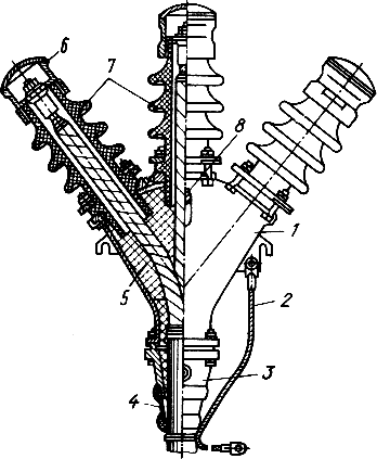
Fig.11. End coupling KN outdoor installation:
1 - housing, 2 - ground wire, 3 - frame, 4 - lead cuff, 5 - potting compound, 6 - contact head, 7 - insulator,
8 - filling hole
Cables with plastic insulation with a voltage of 1 and 6 kV are terminated with PKNR epoxy couplings. To seal the root of the cutting, the coupling has a cone-shaped body, cast from an epoxy compound at the installation site. The cable cores are insulated with polyvinyl chloride heat-shrinkable tubes, on top of which pre-cast epoxy insulators ("skirts") are glued.
Questions for training specialists:
1. Name the main structural elements of the cable and give a description of each of them.
2. What are the requirements for cable lines?
3. How are cables laid in a trench in winter conditions?
4. Name the main operations performed during the stepped cutting of the cable.
5. How are the ends of the cables connected in cast iron, lead and epoxy couplings?
6. Name the ways of making cable terminations.
We advise you to read
, diagnosis, treatment Treatment of urogenital chlamydia") Chlamydia urogenital - description, causes, symptoms (signs), diagnosis, treatment Treatment of urogenital chlamydia
Chlamydia urogenital - description, causes, symptoms (signs), diagnosis, treatment Treatment of urogenital chlamydia The benefits and significance of hydroamino acid threonine for the human body L threonine what
 To wait or not to wait for a guy from the army For what reason can they be commissioned from the army
 Baked apples with cottage cheese Baked apples with cottage cheese

