Page 1
The specific resistance of the conductor depends on temperature, pressure, material, etc., as a result of which the resistance of the conductor also depends on these factors. Of greatest practical importance is the dependence of resistivity, and hence the resistance of the conductor, on temperature. AT general case this relationship is quite complex.
The specific resistance of conductors is not a constant value, but depends on temperature. For all metals, resistance increases with increasing temperature. For small temperature fluctuations, the dependence of resistivity on temperature follows a linear law. For each metal, there is a certain temperature coefficient of resistance a, which determines the change in the resistivity of the conductor, referred to one ohm with an increase in temperature by GS.
The specific resistance of conductors ranges from 10 - 6 to 10 - 2 ohm-cm, and technical dielectrics from 109 to 1020 ohm-cm. These limits are arbitrary to a certain extent, but they approximately reflect the representations established in technology.
The specific resistance of a conductor is the resistance of a wire with a length of I m and a cross-sectional area of 1 mm2 at a temperature of 20 C.
The resistivity of conductors and non-conductors depends on temperature.
The specific resistance of conductors of the first kind depends on temperature. As a rule, it increases with increasing temperature. The exceptions are graphite and coal.
The lower the resistivity of the conductor, the less heat (at the same current) is released in it. In the state of superconductivity, when the resistivity becomes immeasurably small, no noticeable amount of heat is released in the conductor during the passage of current. Since in this case the energy of the current is not wasted anywhere, then once excited in a closed superconductor then; is maintained in it indefinitely without the expenditure of energy from the outside.
A change in the resistivity of a conductor under the action of tensile or compressive forces is called the tensoresistive effect. It is characterized by strain sensitivity, which establishes a relationship between the relative change in resistance and relative deformation.
Here p is the resistivity of the conductor, the rest of the designations are deciphered in the previous problem.
What determines the resistivity of a conductor.
If the value of the resistivity of the conductor p did not depend on its temperature, the ratio between the allowable current density / 1DOp and the allowable temperature rise of the conductor at short circuit would be relatively simple. In reality, the resistivity p changes as the conductor heats up, and the relationship between current density and temperature rise becomes more complex.
To increase the resistivity of conductors, alloys of several metals are used. It has been established that only alloys with a disordered structure have high values of resistivity and low values of the temperature coefficient of resistance. Alloys with a disordered structure are called those in the crystal lattice of which there is no regular alternation of metal atoms that make up the alloy. These alloys constitute a group of conductive materials with high resistivity and low values of the temperature coefficient of resistivity. All of the listed groups of conductors have high plasticity, which makes it possible to obtain wires with a diameter of up to 0.01 mm and tapes with a thickness of 0.05 - 0.1 mm.
The resistance of a conductor depends on its size and shape, as well as on the material from which the conductor is made.
For a homogeneous linear conductor, the resistance R is directly proportional to its length ℓ and inversely proportional to its cross-sectional area S:
where ρ is the specific electrical resistance characterizing the material of the conductor.
§ 13.4 Parallel and series connection of conductors
At series connection of conductors
a  ) the current strength in all sections of the circuit is the same, i.e.
b) the total voltage in the circuit is equal to the sum of the voltages in its individual sections:
![]()
c) the total resistance of the circuit is equal to the sum of the resistances of the individual conductors:
 or
or 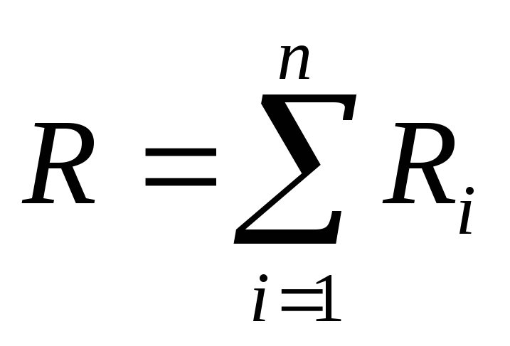 (13.23)
 At parallel connection of conductors the following three laws apply:
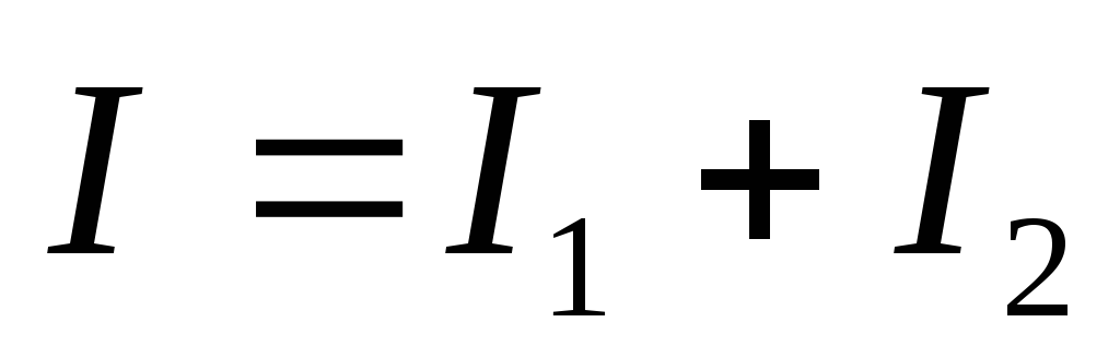
a) the total current in the circuit is equal to the sum of the currents in the individual conductors:
b) the voltage on all parallel connected sections of the circuit is the same:
c) the reciprocal of the total resistance of the circuit is equal to the sum of the reciprocals of the resistance of each of the conductors separately:
 or
or  (13.24)
§ 13.5 Branched electrical circuits. Kirchhoff rules
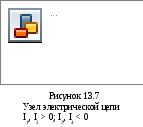
When solving problems, along with Ohm's law, it is convenient to use two Kirchhoff rules. When assembling complex electrical circuits, several conductors converge at some points. Such points are called nodes.
Kirchhoff's first rule is based on the following considerations. The currents flowing into a given node bring a charge into it. The currents flowing from the node carry away the charge. A node cannot accumulate a charge, so the amount of charge entering a given node in a certain time is exactly equal to the amount of charge carried away from the node in the same time. Currents flowing into a given node are considered positive, currents flowing out of a node are considered negative.
According to Kirchhoff's first rule , the algebraic sum of the strengths of the currents in the conductors connecting at the node is equal to zero.
 (13.25)
I 1 + I 2 + I 3 +….+ I n =0
I 1 + I 2 \u003d I 3 + I 4
I 1 + I 2 - I 3 - I 4 =0
Kirchhoff's second rule: the algebraic sum of the products of the resistance of each of the sections of any closed circuit of a branched DC circuit and the current strength in this section is equal to the algebraic sum of the EMF along this circuit .
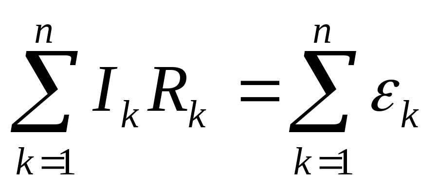 (13.26)
E  This rule is especially convenient to apply in the case when the conducting circuit contains not one, but several current sources (Fig. 13.8).
When using this rule, the directions of the currents and bypass are chosen arbitrarily. Currents flowing along the selected loop bypass direction are considered positive, and currents flowing against the bypass direction are considered negative. Accordingly, the EMF of those sources that cause a current that coincides in direction with the circuit bypass is considered positive.
ε 2 –ε 1 =Ir 1 +Ir 2 +IR (13.27)
Page 2
The temperature dependence of the resistance of metal conductors is widely used in engineering to create resistance thermometers. By placing a spiral of known resistance 7.0 into the furnace and measuring its resistance Rt, one can determine the temperature i of the furnace according to (15.10). On the other hand, this temperature dependence has bad influence on the operation of precision electrical measuring instruments, changing the resistance of the latter when external conditions change.
According to the electronic theory, the resistance of metal conductors to electric current arises due to the fact that current carriers - conduction electrons, during their movement, experience collisions with ions crystal lattice. In this case, the moving electrons transfer to the ions part of their energy acquired by them during their free path in electric field. The difference in the resistance of various metals is explained by the difference in the mean free path of electrons and the number of free electrons per unit volume of the metal.
With an increase in temperature, the resistance of metal conductors increases, and with a decrease, it decreases.
When the temperature changes, the resistance of metal conductors changes (at ordinary temperatures) according to the law R Ro (1 - f - 0 004&), where / 4 is the resistance at 0 C and & is the temperature in Celsius. This law is valid for most pure metals. A conductor whose resistance at 0 C is 10 ohms is uniformly heated from 8j 20 to 02 200 within 10 minutes. At this time, a current under a voltage of 120 V flows through it.
According to the electronic theory, the resistance of metal conductors to electric current arises due to the fact that current carriers - conduction electrons, during their movements, experience collisions with ions of the crystal lattice. In this case, the moving electrons transfer to the ions part of their energy acquired by them during their free run in the electric field. The difference in the resistance of various metals is explained by the difference in the mean free path of electrons and the number of free electrons per unit volume of the metal.
What determines the resistance of a metal conductor.
When the temperature changes, the resistance of metal conductors changes (at ordinary temperatures) according to the law R RQ (l 0 0040), where D0 is the resistance at 0 C and 9 is the temperature in Celsius. This law is valid for most pure metals. A conductor whose resistance at 0 C is 100 m is uniformly heated from 0 20 to 02 200 within 10 minutes.
With an increase in temperature, the resistance of metal conductors increases, and with a decrease, it decreases.
When the temperature changes, the resistance of metal conductors changes (at ordinary temperatures) according to the law R - R0 (l - f 0 0046), where Ro is the resistance at O GC and 6 is the temperature in Celsius. This law is valid for most pure metals. A conductor whose resistance at 0 C is 10 ohms is uniformly heated from 8i 20 to 62 200 Oe within 10 minutes. At this time, a current under a voltage of 120 V flows through it.
Experiments show that the resistance of metal conductors depends on the size of the conductor and the material from which the conductor is made.
What phenomenon leads to an increase in the resistance of a given metal conductor.
AR and CR, is determined by the ratio of the resistances of the metal conductors between the frame and the cathode, on the one hand, and between the frame and the anode, on the other hand. If you choose the resistance of the conductor connecting the frame to the anode, so that each of the values of AR and CR is in the range of 0 8 - 1 5 V (with a voltage on the cell of 2 3 V), then the frame will not be able to participate in the electrochemical process on its surface no gaseous hydrogen or oxygen will be released. If, however, the frame is connected to the anode using a low-resistance conductor, the frame potential can shift to the anode side so much that the frame surface will be involved in electrochemical work as an anode with the release of oxygen into the cathode space and contamination of hydrogen with oxygen.
The resistance method is based on taking into account the change in the resistance of a metal conductor from its temperature.
The total resistance of the grounding device is the sum of the resistances of metal conductors, grounding descents and the resistance that the earth exerts to spreading electric current. The active resistance of metal conductors and grounding leads is so small compared to the spreading resistance that it is usually neglected. Therefore, the term resistance of a grounding device means nothing more than the resistance that the earth surrounding metal conductors provides to the passage of electric current. In the process of current draining into the ground, the ground electrode acquires a potential in relation to remote points of the earth, equal in magnitude to the voltage drop caused by the current passing in the ground.


