Page 1 of 4
Mounting preparation.
For each construction site, design estimates are developed, in accordance with which construction work is carried out on the installation of technological, sanitary, electrical equipment, automation, communications, etc.
Working drawings for the construction of industrial enterprises consist of sets of architectural, construction, sanitary, electrical and technological drawings.
A set of electrical working drawings contains the documentation required for the installation of external and internal electrical networks, substations and other power supply devices, power and lighting electrical equipment. Upon acceptance working documentation before the production of work, it is mandatory to check that it takes into account the requirements of the industrialization of the installation of electrical devices, as well as the mechanization of work on laying cables, rigging of units and blocks of electrical equipment and their installation.
Directly at the place of installation of equipment and laying of electrical networks in workshops, buildings (in the installation zone), installation work should be reduced to the installation of large blocks of electrical devices, the assembly of their nodes and the laying of networks.
In accordance with this, working drawings are completed according to their purpose: for procurement work, i.e., for ordering blocks and assemblies at enterprises or at assembly and assembly enterprises, installation organizations and in electrical assembly workpiece workshops (MEZ), and for the installation of electrical devices in the installation room zone.
The projects provide for the maximum exclusion of punching work at the installation site.
For the installation of power electrical equipment, floor plans of buildings and workshops are developed with indication and coordination of routes for laying supply and distribution power networks and placement of bus ducts, power supply points and cabinets, electrical receivers and control gears. For the installation of electric lighting, floor plans of buildings and workshops are performed with the indication and coordination of supply and group lighting networks, lamps, points and shields on them.
Develop basic and design diagrams of power and lighting equipment.
They check the availability of drawings or sketches for mounting units and blocks (busbars, grounding, lighting, etc.), and in the absence of them, the possibility of grouping disparate devices and products into enlarged blocks. They draw up sketches for their assembly in workshops, replace the products, designs and parts of individual execution adopted in the project with unified factory-made ones.
In some cases, the method of installation of electrical networks and the type of electrical wiring provided for by the project are replaced, for example, instead of laying the AVRG brand cable directly along the walls, cable wiring is used to illuminate the control corridor.
Installation of overhead power lines with a voltage of 0.4-35 kV.
When designing a line, first determine the route (a route is a strip of the surface of the earth along which an overhead line passes) on the map, trying to choose its direction as straight as possible, but at the same time avoiding laying a line in the forest, through swamps and other inconvenient places, as well as unnecessary crossings over other lines, roads and other obstacles. lines high voltage, except for the case of their joint suspension with low-voltage lines, should not be laid in populated areas. When choosing a route, the presence of roads in the immediate vicinity of it is provided for ease of installation and maintenance of the future overhead line. The final direction of the route of the line is chosen when surveying the area.
When passing an overhead line with a voltage of over 1 kV, a clearing is cut through the forest. Clearing width for overhead lines with voltage up to 35 kV inclusive at forest height H < 4 м должна быть не менее чем D+ 6 m, and at the height of the forest H> 4 m - not less than D+ 2H, where D- distance between the extreme wires of the line, m. At the height of the forest H < 4 м деревья, растущие на краю просеки, необходимо вырубить, если их высота больше высоты основного лесного массива. Для воздушных линий напряжением до 1 кВ просеку в лесу вырубать не нужно. При этом вертикальные и горизонтальные расстояния от проводов до вершин деревьев, кустов и прочей растительности должны быть не менее 1 м.
Fig.2.1. Pit for the installation of a single-column support.
The most time-consuming part of the construction of overhead lines is earthworks. Figure 2.1. shows a pit for a single-column support, dug by hand (dimensions are given in meters). For convenience during work and to facilitate the subsequent installation of the support, it is dug in ledges. On straight sections, pits are dug along the line. For corner supports, they dig so that the untouched wall is on the side of the wires. A large stone is placed at the bottom, and in case of weak soil, the bottom is strengthened with several stones. For complex supports, pits are dug in the same way as for a single-column. If a complex support does not have underground screeds, then a separate pit is prepared for each of its legs. wooden supports they are transported along the route and laid near dug pits.
Hooks or pins with insulators are preliminarily fixed on the supports. Cable yarn or hemp impregnated with red lead mixed with drying oil is wound onto hooks or pins. For these purposes, plastic caps are also used.
Hooks with insulators attached to them are screwed into the support post. To do this, holes are drilled in the support with a drill, into which hooks are screwed with a special key. The insulators on the pins are mounted on traverses, to which the pins are attached with nuts.
When constructing individual lines of short length, the work is carried out manually. All lines of considerable length are constructed using mechanisms.
Single-column supports are installed manually - with hooks and tongs, by a team of 6 ... 7 workers or using various equipment (tractor, crane, car or crane drilling machine). Heavy and complex supports are installed with a fixed boom in the form of a column about 10 m long. The lifting cable is pulled by a tractor or a winch. You can also use a "falling boom", that is, a mast that is raised along with the support being installed.
The correct installation of the raised supports is checked by a plumb line, as well as along the axis of the line. The verified supports are fixed in the pit with soil taken out of it. The soil is covered with layers 150 ... 200 mm thick. Each layer is carefully compacted.
After installing supports under them along the route, the lines roll out wires, which are usually delivered on reels. They are rolled out on raised drums to avoid twisting the wire and forming loops.
It is possible to connect wires in a span with a twist only on lines with a voltage of up to 1 kV. In other cases, the wires are connected with oval crimp connectors. The wires to be connected are inserted into the oval connector sleeve and twisted 3.5 ... 4 times, or with special tongs on the sleeve, notches are made in a checkerboard pattern. 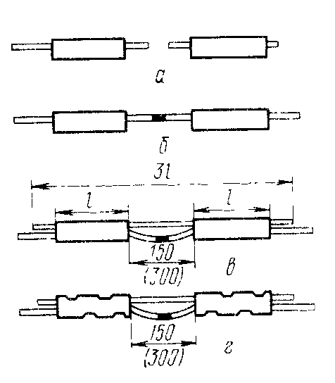
Fig.2.2. Connection of aluminum and steel-aluminum wires by heat welding: a) prepared wire ends; b) the ends of the wires after welding; c) in connectors a shunt is inserted from a piece of wire; d) wire and shunt after crimping connectors.
Aluminum and steel-aluminum wires are also connected by thermite welding. Then, with the help of connectors, a shunt is strengthened from a wire of the same brand (Fig. 2.2) in order to unload the welding site from mechanical stress. Welding is carried out with thermite cartridges ignited by special thermite matches.
Wire connections must have a mechanical strength of at least 90% of the strength of the whole wire. The connection points of the wires are protected from moisture. To do this, the ends of the connectors are painted over with red lead. Splicing wires in a span crossing other lines is not allowed.
Wires rolled out on the ground are lifted onto supports with poles or ropes, for which the fitter climbs onto the support. The raised wires are laid on the hooks of insulators or on special mounting rollers. After that, the wires are fixed on one of the anchor supports and pulled over the entire anchor span.
The wires of low voltage lines are pulled manually - with a chain hoist, high voltage lines with large spans - with a tractor or winch. aluminum wires at the same time, they are clamped in a special wooden clamp, and steel and copper are captured with metal wedge clamps.
The sag of the wires is set in accordance with the mounting table depending on the air temperature or is determined by the force with which the wire is pulled. The force is measured by a dynamometer attached to the wire. The sag is determined by sighting from one support to another. To do this, rails with divisions are strengthened on two adjacent supports. An installer climbs onto one of the supports. At his command, the tension of the wire is stopped when the sag reaches a predetermined value.
On the overhead lines low voltage, if on the same. wires of different sections are fixed to the same support, the sag of all wires is made the same.
When the wire is stretched, it is attached to the final anchor support, and then to the insulators of all intermediate supports. Wires are attached to pin insulators with special clamps or wire - viscous (Fig. 2.3).
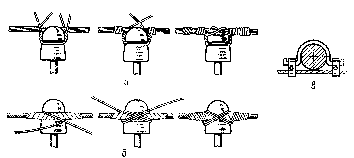
Fig.2.3. Fastening the wire to the pin insulators on the intermediate support:
a) wire to the head of the insulator; b) wire to the neck of the insulator; c) clamp to the neck of the insulator.
The aluminum wire is tied to the insulator with aluminum wire, the steel wire is tied with soft galvanized steel wire with a diameter of 3.5 mm and 2.0 ... 2.7 mm, respectively.
On pin insulators, the wires are attached to the neck or head of the insulator. On corner supports, the wires are attached only to the neck of the insulator. Clamps are also used. On the garlands of suspension insulators, the wires are fixed only with clamps. To protect the outer surface of aluminum and steel-aluminum wires, they are wrapped with aluminum tape 1 mm thick.
When laying wires on hooks, tying them to insulators, installing lanterns street lighting use a lifting tower made of several pipes of different diameters. In the stowed position, the pipes enter one into the other, so the tower is called telescopic. In the working position, it is installed vertically and pushed apart by the car engine. Two fitters stand on a platform with mesh walls and rise to a height of up to 26 m.
For lifting to a height of up to 20 m, hydraulic lifts are also used on cars. The hydraulic lift consists of a rotating turret tower and two tubular elbows, at the ends of which there are two cradles for fitters. The tower is rotated and the knees are set in working motion with the help of hydraulic cylinders. Remote control both from the ground and from the lift cradle. Due to this, as well as the large outreach of cradles from one parking lot, it is possible to perform all riding work on a support when installing overhead lines with a voltage of up to 35 kV.
1.doc
1. Preparation of installation. 2
2. Installation of overhead power lines with a voltage of 0.4-35 kV. 3
3. Installation of power and control cables. 7
4. Installation of grounding devices. ten
4.1. Installation of natural grounding devices. ten
4.2. Installation of artificial grounding devices. eleven
4.3. Installation of grounding and zero protective conductors. 13
Literature 18
- ^
Mounting preparation.
For each construction site, design estimates are developed, in accordance with which construction work is carried out on the installation of technological, sanitary, electrical equipment, automation, communications, etc.
Working drawings for the construction of industrial enterprises consist of sets of architectural, construction, sanitary, electrical and technological drawings.
A set of electrical working drawings contains the documentation required for the installation of external and internal electrical networks, substations and other power supply devices, power and lighting electrical equipment. When accepting working documentation for the production of work, it is mandatory to check that it takes into account the requirements of the industrialization of the installation of electrical devices, as well as the mechanization of work on laying cables, rigging of units and blocks of electrical equipment and their installation.
Directly at the place of installation of equipment and laying of electrical networks in workshops, buildings (in the installation zone), installation work should be reduced to the installation of large blocks of electrical devices, the assembly of their nodes and the laying of networks.
In accordance with this, working drawings are completed according to their purpose: for procurement work, i.e., for ordering blocks and assemblies at enterprises or at assembly and assembly enterprises, installation organizations and in electrical assembly workpiece workshops (MEZ), and for the installation of electrical devices in the installation room zone.
The projects provide for the maximum exclusion of punching work at the installation site.
For the installation of power electrical equipment, floor plans of buildings and workshops are developed with indication and coordination of routes for laying supply and distribution power networks and placement of bus ducts, power supply points and cabinets, electrical receivers and control gears. For the installation of electric lighting, floor plans of buildings and workshops are performed with the indication and coordination of supply and group lighting networks, lamps, points and shields on them.
Develop basic and design diagrams of power and lighting equipment.
They check the availability of drawings or sketches for mounting units and blocks (busbars, grounding, lighting, etc.), and in the absence of them, the possibility of grouping disparate devices and products into enlarged blocks. They draw up sketches for their assembly in workshops, replace the products, designs and parts of individual execution adopted in the project with unified factory-made ones.
In some cases, the method of installation of electrical networks and the type of electrical wiring provided for by the project are replaced, for example, instead of laying the AVRG brand cable directly along the walls, cable wiring is used to illuminate the control corridor.
- ^
Installation of overhead power lines with a voltage of 0.4-35 kV.
When designing a line, first determine the route (a route is a strip of the surface of the earth along which an overhead line passes) on the map, trying to choose its direction as straight as possible, but at the same time avoiding laying a line in the forest, through swamps and other inconvenient places, as well as unnecessary crossings over other lines, roads and other obstacles. High voltage lines, except for the case of their joint suspension with low voltage lines, should not be laid in populated areas. When choosing a route, the presence of roads in the immediate vicinity of it is provided for ease of installation and maintenance of the future overhead line. The final direction of the route of the line is chosen when surveying the area.
When passing an overhead line with a voltage of over 1 kV, a clearing is cut through the forest. Clearing width for overhead lines with voltage up to 35 kV inclusive at forest height H < 4 м должна быть не менее чем D 6 m, and at the height of the forest H> 4 m - not less than D 2H, where D- distance between the extreme wires of the line, m. At the height of the forest H < 4 м деревья, растущие на краю просеки, необходимо вырубить, если их высота больше высоты основного лесного массива. Для воздушных линий напряжением до 1 кВ просеку в лесу вырубать не нужно. При этом вертикальные и горизонтальные расстояния от проводов до вершин деревьев, кустов и прочей растительности должны быть не менее 1 м.
H
Fig.2.1. Pit for the installation of a single-column support.
The most time-consuming part of the construction of overhead lines is earthworks. Figure 2.1. shows a pit for a single-column support, dug by hand (dimensions are given in meters). For convenience during work and to facilitate the subsequent installation of the support, it is dug in ledges. On straight sections, pits are dug along the line. For corner supports, they dig so that the untouched wall is on the side of the wires. A large stone is placed at the bottom, and in case of weak soil, the bottom is strengthened with several stones. For complex supports, pits are dug in the same way as for a single-column. If a complex support does not have underground screeds, then a separate pit is prepared for each of its legs. Wooden supports are transported along the route and laid near the dug pits.
Hooks or pins with insulators are preliminarily fixed on the supports. Cable yarn or hemp impregnated with red lead mixed with drying oil is wound onto hooks or pins. For these purposes, plastic caps are also used.
Hooks with insulators attached to them are screwed into the support post. To do this, holes are drilled in the support with a drill, into which hooks are screwed with a special key. The insulators on the pins are mounted on traverses, to which the pins are attached with nuts.
When constructing individual lines of short length, the work is carried out manually. All lines of considerable length are constructed using mechanisms.
Single-column supports are installed manually - with hooks and tongs, by a team of 6 ... 7 workers or using various equipment (tractor, crane, car or crane drilling machine). Heavy and complex supports are installed with a fixed boom in the form of a column about 10 m long. The lifting cable is pulled by a tractor or a winch. You can also use a "falling boom", that is, a mast that is raised along with the support being installed.
The correct installation of the raised supports is checked by a plumb line, as well as along the axis of the line. The verified supports are fixed in the pit with soil taken out of it. The soil is covered with layers 150 ... 200 mm thick. Each layer is carefully compacted.
After installing supports under them along the route, the lines roll out wires, which are usually delivered on reels. They are rolled out on raised drums to avoid twisting the wire and forming loops.
FROM it is possible to connect wires in a span by twisting only on lines with a voltage of up to 1 kV. In other cases, the wires are connected with oval crimp connectors. The wires to be connected are inserted into the oval connector sleeve and twisted 3.5 ... 4 times, or with special tongs on the sleeve, notches are made in a checkerboard pattern.
BUT
Fig.2.2. Connection of aluminum and steel-aluminum wires by heat welding: a) prepared wire ends; b) the ends of the wires after welding; c) in connectors a shunt is inserted from a piece of wire; d) wire and shunt after crimping connectors.
aluminum and steel-aluminum wires are also connected by thermite welding. Then, with the help of connectors, a shunt is strengthened from a wire of the same brand (Fig. 2.2) in order to unload the welding site from mechanical stress. Welding is carried out with thermite cartridges ignited by special thermite matches.
Wire connections must have a mechanical strength of at least 90% of the strength of the whole wire. The connection points of the wires are protected from moisture. To do this, the ends of the connectors are painted over with red lead. Splicing wires in a span crossing other lines is not allowed.
Wires rolled out on the ground are lifted onto supports with poles or ropes, for which the fitter climbs onto the support. The raised wires are laid on the hooks of insulators or on special mounting rollers. After that, the wires are fixed on one of the anchor supports and pulled over the entire anchor span.
The wires of low voltage lines are pulled manually - with a chain hoist, high voltage lines with large spans - with a tractor or winch. At the same time, aluminum wires are clamped in a special wooden clamp, and steel and copper wires are captured with metal wedge clamps.
The sag of the wires is set in accordance with the mounting table depending on the air temperature or is determined by the force with which the wire is pulled. The force is measured by a dynamometer attached to the wire. The sag is determined by sighting from one support to another. To do this, rails with divisions are strengthened on two adjacent supports. An installer climbs onto one of the supports. At his command, the tension of the wire is stopped when the sag reaches a predetermined value.
On low voltage overhead lines, if on the same one. wires of different sections are fixed to the same support, the sag of all wires is made the same.
When the wire is taut, it is attached to the final anchor support, and then to the insulators of all intermediate supports. Wires are attached to pin insulators with special clamps or wire - viscous (Fig. 2.3).
Fig.2.3. Fastening the wire to the pin insulators on the intermediate support:
a) wire to the head of the insulator; b) wire to the neck of the insulator; c) clamp to the neck of the insulator.
The aluminum wire is tied to the insulator with aluminum wire, the steel wire is tied with soft galvanized steel wire with a diameter of 3.5 mm and 2.0 ... 2.7 mm, respectively.
On pin insulators, the wires are attached to the neck or head of the insulator. On corner supports, the wires are attached only to the neck of the insulator. Clamps are also used. On the garlands of suspension insulators, the wires are fixed only with clamps. To protect the outer surface of aluminum and steel-aluminum wires, they are wrapped with aluminum tape 1 mm thick.
When laying wires on hooks, tying them to insulators, installing street lighting lamps, they use a lifting tower made of several pipes of different diameters. In the stowed position, the pipes enter one into the other, so the tower is called telescopic. In the working position, it is installed vertically and pushed apart by the car engine. Two fitters stand on a platform with mesh walls and rise to a height of up to 26 m.
For lifting to a height of up to 20 m, hydraulic lifts are also used on cars. The hydraulic lift consists of a rotating tower-turret and two tubular elbows, at the ends of which there are two cradles for fitters. The tower is rotated and the knees are set in working motion with the help of hydraulic cylinders. Remote control both from the ground and from the lift cradle. Due to this, as well as the large reach of the cradles from one parking lot, it is possible to perform all riding work on the support when installing overhead lines with a voltage of up to 35 kV.
- ^
Installation of power and control cables.
Cables are laid in trenches 700 mm deep in one horizontal row, on a bed of sand or sifted earth (Fig. 3.1). From above, the cable is covered with the same layer.
The earth tightly fits the cable and removes heat from it well. To protect the cable from mechanical damage, a row of bricks is placed on it along the direction of the trench.
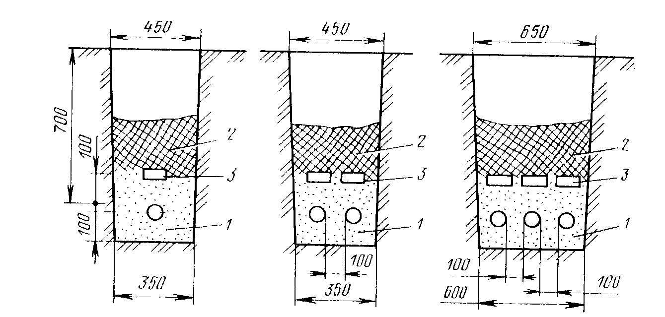
Fig.3.1. Section of a trench for laying a cable with a voltage of up to 10 kV:
1- sand or sifted earth; 2 - ground land; 3- bricks.
When laying cables in the ground, more than 75% of the time is spent digging and backfilling trenches, if this work is done manually. When performing earthworks, a bucket-wheel excavator is used to dig trenches and a bulldozer is used to backfill them.
With mechanized laying of cables, they can not be protected from damage by bricks, but then the trench depth should be increased to 1000 ... 1200 mm.
At turns, a trench is dug so that the radius of curvature of a three-core lead-lined cable with paper insulation is at least 15 outer diameters (single-core - 25 diameters), with an aluminum sheath - at least 20 outer diameters. At the junction of cables in the couplings, the trenches are expanded to 1.5 m in a section 2 m long.
The cable can be laid into the trench by hand. To facilitate this work, as well as to reduce the time for its implementation, mechanized laying is used. With mechanized laying, the cable drum is installed on jacks and raised to the desired height. The cable is moved manually or by a winch on a car along special rollers installed at the bottom of the trench, and laid on the bottom of the trench with a snake. The length of the cable should be approximately 1% longer than the length of the trench.
In populated areas, when crossing a road, etc., it is advisable to lay cables in blocks of ceramic or asbestos-cement pipes. Concrete blocks with one and several holes are also used. The diameter of the hole in the block must exceed the outer diameter of the cable by at least 1.5 times.
The blocks are placed at the bottom of the trench and connected with a liquid cement mortar, tar or resin. Every 70 ... 100 m, wells are made, which serve to pull cables into the holes of the blocks, to connect and branch cables in couplings. The blocks are laid with some slope so that the water drains from them.
Previously, a special cylinder is pulled through the blocks to check if there are protrusions in the pipes. If there are protrusions, they are cleaned by stretching a metal brush. Then the cable is pulled into the blocks, lubricating its surface with technical petroleum jelly. Usually, when assembling blocks, a wire is left in them to pull the cable. Cables are laid in segments from one well to another, where they are connected by couplings.
In rooms, cables are laid openly on brackets or in clamps. The distance between adjacent cable mounts is 800 ... 1000 mm for horizontal and up to 2000 mm for vertical installation. Use cables without a protective cover. The outer surface of the lead sheath of the cable is coated with bitumen or painted. The distance between power cables in the light should be at least 35 mm. In passages through walls and ceilings, cables are laid in sections of steel or asbestos-cement pipes. In places where mechanical damage to the cables is possible, they are protected with steel pipes or pieces of angle steel at a height of up to 2 m from the level of the iol.
 AT
AT
Fig.3.2. Cable termination in steel terminalfunnel:
1. Tile paper and tarredribbon; 2.leadshell; 3. hard thread bandageon the waistisolation;
4. funnel cover;
5. porcelainsleeve; 6. core wrappedinsulating tape; 7.place for soldering the ground wire; eight.steel clamp forfunnel attachments;
9.ground wire.
indoors, hidden laying of cables in channels or in steel pipes is also used. From above, the channels are closed with reinforced concrete or steel slabs. For better cooling, the distance between the cables in the channels should be at least 50 mm.
AT 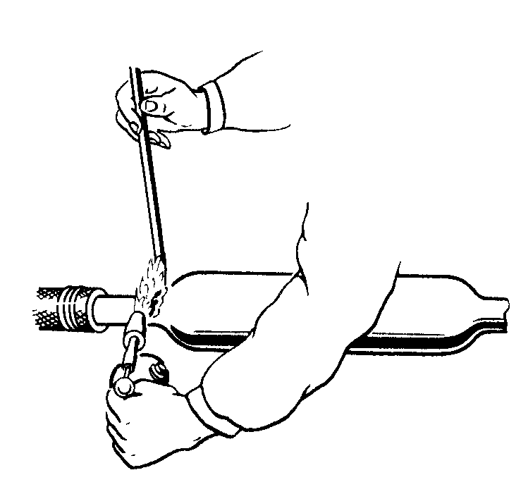 All connections and branches of cables are made in sleeves that protect the cable from moisture and protect the junction from mechanical damage. Before installing the coupling, the cable is cut, that is, the protective sheaths are removed from it, having previously applied two wire bandages to the cable at a distance of 150 ... 200 mm from one another. The cable cores are bred and bent so that the bending radius of the core is at least ten of its diameters. Then they are introduced into the holes of spacer porcelain plates (bridges). The conductors are connected with sleeves, followed by soldering or crimping with a hydraulic press. The metal sheaths of the cable are grounded. The sleeve is filled with cable mass.
To
Fig.3.3. Soldering the lead sleeve to the lead sheath of the cable
cable termination at voltages of 6 and 10 kV is carried out in a steel funnel (Fig. 3.2.). The funnel is filled with cable mass. For cables with voltages above 1 kV, lead sleeves are used, made in the form of a piece of lead pipe, pushed over the junction and soldered on both sides to the lead sheath of the cable (Fig. 3.3.). Two holes are cut in the upper part of the coupling, through one of which the cable mass is poured into the coupling. The cable cores in a lead sleeve are insulated with paper tape or yarn. Porcelain bridges are not used.
P 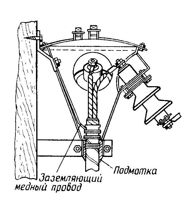 When switching from a cable line to an air line or vice versa, mast couplings are used (Fig. 3.4). Couplings of this type are installed on supports in the open air.
W
Fig.3.4. Mast Steel Coupling
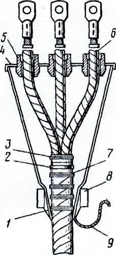
pouring the sleeves with cable mass is a complex and responsible operation that can only be performed by highly qualified workers. It requires careful adherence to safety regulations. To avoid the use of bulky terminations filled with cable mass, paper-insulated cables without couplings are terminated - dry termination. With this method, the cut cable cores are insulated with a cotton varnished tape. Each layer of the tape is covered with an insulating varnish. On the cores wrapped with tape, put on with 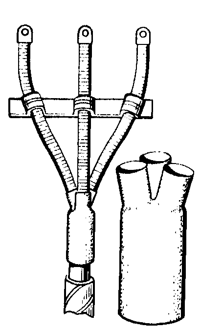 a screw cap-glove with processes-fingers (Fig. 3.5). The bottom of the glove is soldered to the lead sheath of the cable. The cable cores, part of the fingers and cable lugs are wrapped with taffeta tape, varnished, and the lead glove is poured with oil-rosin mass. In some cases, a lead glove is not used, but is limited to wrapping the cable cores with varnished cloth tapes, followed by varnishing. Recently, dry cable terminations have been carried out using vinyl chloride l
^
Fig.3.5. Dry termination of cable with lead glove
tape, which does not require varnishing of each layer of the winding. The entire seal is covered with PVC enamel.
Cables up to 10 kV are connected with epoxy sleeves. A mold is put on the junction and the epoxy compound is poured. After a day, the compound hardens and turns into a monolithic cable connection. Then the form is removed - and the seal is ready. Please note that epoxy resins are poisonous and should be handled with care.
- ^
Installation of grounding devices.
Installation of natural grounding devices.
If the project provides for the use of protective properties of building structures, then the following options are possible:
1) in the case of a steel frame building, no additional work to create a grounding device from electricians is not required. Grounding of the transformer neutral, as well as equipment cases, electrical structures should be carried out by welding the ground conductor to the building column or to building structures that are connected to the building frame;
2) in the case of a reinforced concrete frame, it is necessary for electricians, together with builders, to organize the acceptance of work on connecting embedded products of columns and foundations (Fig. 4.1.1) and other connections of reinforced concrete products that ensure the integration of reinforced concrete frame reinforcement into a single whole.
The zero connection of the transformer with the embedded product is carried out by welding the grounding conductor to the embedded element of the column or foundation. Grounding (connection using a grounding conductor) of electrical equipment cases, electrical structures should be carried out by welding to embedded products on columns. It is forbidden to weld the grounding conductor to the armature with 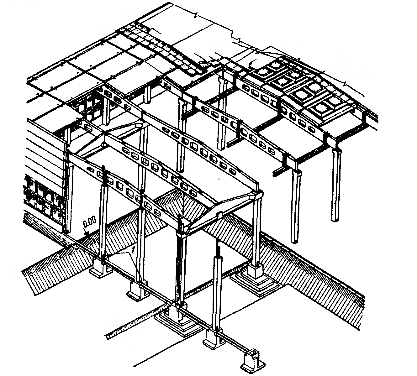 shade panels.
M
Fig.4.1.1. Installation of ground jumpers when using rafters and rafters to connect the metal fittings of the building:1. embedded products with jumpers
installation of artificial grounding devices.
Installation of earth conductors. Before the start of electrical installation work, the construction organization must complete work on the layout, trench or pit.
The following are used as artificial grounding conductors:
Recessed ground electrodes - strips or round steel laid horizontally on the bottom of a pit or trench in the form of extended elements;
vertical grounding - steel screw-in rods with a diameter of 12-16 mm, angle steel with a wall thickness of at least 4 mm or steel pipes (substandard with a wall thickness of at least 3.5 mm). The length of the screwed-in electrodes, as a rule, is 4.5–5 m. The distance from one electrode to another must not be less than its length;
horizontal ground electrodes - steel strips with a thickness of at least 4 mm or round steel with a diameter of at least 10 mm. These earthing switches are used to connect vertical earthing switches and as independent grounding switches. Horizontal ground electrodes made of strip steel are laid along the bottom of the trench at a depth of 700-800 mm on the edge.
Electrodes and grounding conductors should not be painted, they should be cleaned of rust, traces of oil, etc. If the soils are aggressive, then galvanized electrodes are used. Immersion of electrodes into the ground is carried out with the help of special devices.
FROM  the connection of the parts of the grounding conductor to each other, as well as the connection of the grounding conductors to the grounding conductors should be carried out - by welding. In the presence of power sources, the connections are made by electric welding. Welded seams located in the ground must be coated with bituminous varnish to protect against corrosion. When working at remote sites and power lines, it is recommended to connect parts of ground electrodes with ground conductors by thermite welding.
FROM
Fig.4.2.1. Types of connection of steel strips and rods made by thermite welding:
a) connecting the rods end-to-end;
b) full butt joint,
c) overlapping strips;
d) overlapping rods;
e) connection of reinforcing steel; c) cable connection
Fig.4.2.2. Branch of steel grounding conductors made by thermite welding:
a) a branch of the rod from the rod; b) branching of the strip from the strip; c) branch of the rod from the strip
welding of steel strips and earth rods. Thermite-crucible welding is used to connect steel strips 25, 30 and 40 mm wide with a thickness of 4-5 mm and rods with a diameter of 12, 14 and 16 mm in ground loops, for connecting loops to ground electrodes, power transmission towers and other steel structures. Types of connections and branches of strips and rods made using thermite welding are shown in fig. 4.2.1, 4.2.2. Thermite welding of steel strips and ground rods requires fixtures and tools. Thermite-crucible welding of steel strips and rods is performed in sand-resin crucible forms of disposable use, manufactured in the workshops of procurement sites of organizations. Crucible molds are made from a mixture of quartz sand with 6% thermosetting resin - pulverized bakelite. The upper part of the mold cavity serves as a crucible in which the thermite reaction takes place with the release of steel; the lower part is a chamber in which welding takes place (melting of welded strips or rods and formation of a welded joint). To fix steel strips and rods for the period of welding, a fixture is used, which is a bracket with clamps attached to it. The retractable tray is designed for sand, which is recommended to sprinkle, crucible-form at the bottom for compaction. In some cases, when the bracket cannot be used due to the conditions for placing the ground loop (limited space), separate clamps are used.
- ^
Installation of grounding and zero protective conductors.
When installing grounding and neutral protective conductors inside buildings in installations up to 1 kV, first of all, you should use zero working conductors of the supply network, metal columns, trusses, crane runways, galleries, elevator and hoist shafts, control station switchboard frames, steel pipes of electrical wiring, aluminum cable sheaths, metal pipelines for all purposes, laid openly, excluding pipelines of combustible and explosive mixtures. All these elements must be securely connected to a grounding device. If they satisfy the requirements for protective conductors in terms of conductivity, then it is not required to lay artificial protective conductors.
Prior to the installation of artificial grounding conductors at the facility, the construction organization must complete and hand over all construction work according to the act.
Work on the installation of artificial grounding conductors should be carried out in the scope provided for by the project, in the following sequence: 1) mark the lines for laying conductors, determine the places of passages and bypasses; 2) drill or punch holes for passages through walls and ceilings; 3) install supports, lay and fix pre-painted grounding conductors or fix conductors with the help of shooting (for dry rooms); 4) connect the conductors to each other by welding; 5) to color the junctions of the conductors.
Parts of the grounding lines and their transportable units (mounting supports, jumpers and other grounding conductors) are made in the workshops of electrical assembly blanks. Flat or round steel used as grounding conductors must be pre-straightened, cleaned and painted on all sides.
The joints must be painted after welding the joints; for this, in dry rooms with a normal environment, oil paints and nitro enamels should be used; in damp rooms and in rooms with chemical active medium painting should be done with paints that are resistant to chemical influences. Grounding conductors are painted yellow-green by sequential alternation of yellow and green stripes of the same width from 15 to 100 mm each. The strips must be adjacent to each other or along the entire length of each conductor, or in every accessible place, or in each section.
Grounding conductors must be laid horizontally or vertically, it is also allowed to lay them parallel to the inclined structures of buildings. The laying of flat grounding conductors on brick and concrete bases should be carried out primarily with the help of a construction and assembly gun. In dry rooms, ground strips can be laid directly on brick and concrete bases. In damp and especially damp rooms and in rooms with chemically active substances, the laying of grounding conductors should be carried out on supports.
Supports for fastening grounding conductors must be installed in compliance with distances, mm:
On corners (from top corners) 100
From branch points 100
From the lower surface of the removable covers of the channels 50
From the floor level of the room……………………………………………………….. 400 - 600
AT  as supports, embedded products in reinforced concrete bases, ground bus holders K188 (Fig. 6.18) are used.
D
Rice. 4.3.1. Ground bus holder:
a) for steel round tires of grounding conductors;
b) for rectangular grounding conductors
K188 ground bus holders are used for fastening to walls and metal structures of ground conductors made of round steel with a diameter of 10.12 mm and of flat steel with a size of 40x4 and 25x3 mm. The holders are fixed by shooting or welding, they have a climatic modification of the V category 2, the weight of 1000 pieces is 75 kg.
The distance from the base surface to the grounding conductors must be at least 10 mm (Fig. 4.3.1).
The holders are attached to embedded products located in the concrete base by means of welding, which is performed along the perimeter of the holder shank, as well as with the help of pistol dowels. The holders are attached to concrete, brick and other bases with the help of pistol dowels, in special cases - with the help of dowels with expansion nut or nylon expansion dowels. The distances between the fastenings of grounding conductors on straight sections are indicated in Table. 4.1.
^
Table 4.1. Distances between fastenings of grounding conductors, mm.
| Conductor dimensions, mm | Place of laying |
||||
| Steel strip | Steel round diameter | along the walls | under the ceiling |
||
| at height, m |
|||||
| up to 2 | over 2 | up to 2 | over 2 |
||
| 20x3 25x4 30x5,40x4 | 8 12 | 400 600 600 | 600 800 800 | 600 800 800 | 800 1000 1000 |
Passages through walls should be carried out in open openings, pipes, and passages through ceilings - in segments of steel or plastic pipe cassettes.
Each grounded part of the electrical installation must be connected to the grounding or grounding line using a separate branch. The method of connecting grounding conductors to individual devices is selected depending on the base on which the device is mounted.
Methods for connecting and connecting grounding and zero protective conductors are given in Table. 4.2.
The connection of electrical equipment that is subject to frequent dismantling, vibration or installed on moving parts is carried out using flexible grounding or zero protective conductors.
Methods for connecting grounding conductors to power equipment cases are indicated in Table. 4.3.
The places of connection and fastening of grounding and zero protective conductors to power equipment are given in GOST 21130-75.
Grounding mounting nuts are used to create electrical contact between the body of the apparatus or electrical structure and steel pipes, branch pipes. Nuts are installed on both sides of the housing wall, with the sharp protrusions facing this wall.
Table 4.2. ^
Connections and connections of grounding and zero protective conductors.
| Connected conductors | Connection methods | Additional requirements for connection quality |
| Grounding and zero protective conductors. | Welding. | 1. Connections and connections of grounding and zero protective conductors must be accessible for inspection. |
| Grounding and bullet protective conductors indoors and outdoors without aggressive media. | It is allowed to make connections of grounding and zero protective conductors in other ways that ensure the requirements of GOST 10434-82 for the 2nd class of connections, while measures must be taken against weakening and corrosion of grounding and zero protective conductors - electrical wiring and overhead lines can be performed by the same methods as and phase conductors | 2. Places and methods of connecting grounding conductors with extended natural grounding lines (for example, with pipelines) must be chosen so that when disconnecting the grounding conductors for repair work, the calculated value of the resistance of the grounding device is provided. Water meters, gate valves should be named, bypass conductors that ensure the continuity of the ground circuit. |
| Steel pipes of electrical wiring, boxes, trays and other structures used as grounding or zero protective conductors. | Must have connections that meet the requirements of GOST 10434-82 for the 2nd class of connections. Reliable contact of steel pipes with electrical equipment housings into which pipes are inserted, and with metal junction (branch) boxes must be ensured. | 3. Each part of the electrical installation to be grounded or grounded must be connected to the grounding or inlining network using a separate branch. Consistent connection to the grounding or zero protective conductor of the grounded or grounded parts of the electrical installation is not allowed. |
| Connection of grounding and zero protective conductors to parts of equipment to be grounded or grounded. | Must be done by welding or bolting. For bolted connection, measures must be taken to prevent loosening and corrosion of the contact connection. | |
| Grounding or grounding of equipment subject to frequent dismantling or mounted on moving parts or parts subject to shock or vibration. | Must be carried out with flexible grounding or zero protective conductors. |
Table 4.3. ^ Ways of connecting conductors to power electrical equipment.
| Equipment | Grounding elements | Method of connection to the ground network |
| Starting device (magnetic starter, box with circuit breaker etc.) control apparatus (push-button post, limit switch, rheostat, controller, etc.), shields, distribution cabinets. | The body of the apparatus, box, shield, cabinet. | The grounding conductor is connected to the grounding or fastening bolt of the device body, box or shield; when installed on a metal structure, the grounding conductor is welded to the structure. If grounding is carried out through electrical wiring pipes, then it is performed: A) by connecting a jumper from a flag or a bolt welded to the pipe to the ground bolt on the body of the apparatus, shield, box. B) installing two scratching nuts or one scratching nut and a locknut on the pipe with a clamp of the steel sheet of the apparatus body between the nuts. |
| Electrical equipment installed on machine tools and other mechanisms. | The body of a machine or mechanism having metallic bond with the motor housing or other equipment. | The grounding conductor coming from the grounding line or from the steel rough electrical wiring (if pipes are used as grounding conductors) is connected to the grounding bolt on the machine (mechanism). Electrical equipment installed on the moving part of the machine is grounded using a separate core in a flexible cable that feeds the moving part. |
| Overhead crane electrical equipment. | Crane rails. | Branches from the grounding device are welded in two places to the crane rails. The weight of the rail joints must be securely connected by welding, flexible jumpers must be welded on the detachable joints. |
Literature
I.A. Buzdko, N.M. Suhl. "Power supply of agriculture". M.: "Agropromizdat", 1990. 496 p.
R.N. Karjakin. "Grounding devices of electrical installations. Directory". M.: CJSC Energoservice, 2002, 373s.
S.A. Burguchev. "Electric stations, substations and systems" M.: "Kolos", 1966. 689 p.
P.A. Katkova, F.A. Frangulyan. "Handbook for the design of electrical networks in rural areas". - M.: "Energy", 1980, 352 p.
Substations include electrical installations that serve to convert and distribute electricity, and switchgear (RU) - installations for its reception and distribution. Substations are built according to standard designs, which contributes to the introduction of industrial methods of construction and installation. At substations and switchgears handed over for installation, access roads, lifting installations should be built, permanent or temporary networks for supplying electricity should be laid, electric lighting should be installed, embedded parts and bases in the floor should be installed and mounting openings should be left for moving large-sized equipment, cable structures should be prepared. and underground communications. In open switchgears, metal and reinforced concrete structures must be installed, aligned and fixed, foundations for equipment must be built.
Installation of substations and switchgear, as well as other electrical installations, is carried out in two stages. At the first stage, all preparatory and procurement work is carried out: electrical equipment, structures and materials are assembled; carry out pre-assembly and revision of equipment. At the second stage, the actual installation of electrical equipment is performed.
The most important condition for the high quality of installation work is the supply of reliable electrical equipment that meets all requirements for installation. Therefore, before installing it, a qualified pre-installation check is organized. The procedure, scope and evaluation criteria during the pre-installation preparation period depend on the type of electrical equipment and are determined by regulatory documents and factory instructions. Minor defects found during the inspection should be eliminated.
INSTALLATION OF INSULATORS AND BAR. in substations and distribution plants use support, bushing and linear (suspended) insulators for indoor and outdoor installations.
Before installation, the insulators are cleaned of dirt and paint, remove solid particles and subjected to a thorough check. At the same time, the quality of the surface of the insulator, the condition of galvanized metal parts, the strength of the reinforcement, the geometric dimensions (selectively), and the insulation resistance are checked.
On the surface of porcelain insulators, there should be no through or surface cracks, inclusions of sand, ceramic material or metal. The area of chips of broken edges should not exceed the values normalized by GOST.
The surface of galvanized metal parts must be free of cracks, shells, wrinkles, nicks, and traces of corrosion. The strength of the reinforcement of insulators is considered sufficient if the caps, flanges, caps do not swing or rotate. The seams of the reinforcing ligament should not have cracks, irregularities and damage to the moisture-resistant coating. The air gap between the edge of the flange, cap or cap and the insulating part must be at least 2 mm for porcelain and 1 mm for glass insulators; the thickness of the seam of the reinforcing ligament is not less than 2 mm; non-parallelism of the end surfaces of the support insulators indoor installation no more than 2 and 1 mm insulators outdoor installation; mismatch of the center, flange, cap or cap with an insulating part - no more than 2 mm. The resistance of the insulator, measured with a megohmmeter for a voltage of 2500V, at a positive temperature must be at least 300 MΩ.
As a rule, post insulators are installed on metal support structures or directly on walls. 4 or overlays. The support and bushing insulators in the switchgear are fixed so that the surfaces of the caps are in the same plane and do not deviate from it by more than 2 mm. The axes of all supporting or bushing insulators standing in a row should not deviate to the side by more than 5 mm. The flanges of post and bushing insulators installed on plastered bases or on bushing plates must not be recessed. Insulators of different phases are placed along one line perpendicular to the phase axis. The bushings are installed on an angle steel frame covered with an asbestos-cement slab or in a concrete slab. The diameters of the holes for bushings in slabs or partitions must be 5-10 mm larger than the diameter of the embedded part of the insulators. Busbar holders are fixed on the mounted insulators. Tire preparation is carried out centrally in specialized workshops. The main works in the preparation of tires include: sorting and selecting them according to sections and lengths; straightening, cutting and bending tires; marking and preparation of holes for collapsible connections; preparation of contact connections.
Individual tires are driven on beams or slabs with hammer blows, through a pad that softens blows. Tire bending is performed according to templates made of steel wire with a diameter of 3-6 mm. Tires are bent flat on edge, corkscrew or duck. In this case, the following conditions must be met: the tire bending radius on the plane must be at least twice the thickness of the tire; in edgewise bends for tires with a width of less than 50 mm, the bending radius must be at least its width, and for a width of more than 50 mm it must be equal to 2 times the width of the tire; when bending into a corkscrew, the length must be at least 2.5 times the tire width. The bending of tires on a plane and an edge is performed on tire benders with ganks or manual tire benders, and with a corkscrew and a duck - on special devices.
When preparing tires for bolting, holes are made by punching on a press or by drilling on a machine. On installed and curved tires, a drill is used to drill holes. For a better fit of the contacting surfaces, longitudinal cuts are made on tires with a width of more than 60 mm. The contact surfaces are processed to remove dirt, preservative grease and film on a tire-cutting machine or with a file coated with a layer of grease. The tires on the insulators are fixed flat or on the edge with the help of planocta to ensure the possibility of their longitudinal movement when the temperature changes. With a large length of tires, to eliminate linear deformations, tire compensators are installed on them, consisting of a package of thin tapes, with a total cross section equal to the cross section of the tire. In the middle of the total length or in the middle of the section between the expansion joints, the tires must be fixed rigidly. The bus supports must not create a closed loop around the tires, for this one of the linings or all the tie bolts located on one side of the bus must be made of non-magnetic material. The laid tires are verified with a stretched wire, a level or a plumb line, since they must lie straight on the insulators, without distortions, without visible transverse curvature and waviness.
Tires are connected by welding or bolts. Welding should be preferred. A bolted connection is used only when, according to operating conditions, its disassembly is necessary. Such a connection for aluminum busbars, aluminum busbars with a copper or aluminum alloy must be replenished using stabilization means - hardware from non-ferrous metals or steel, but using Belleville springs. Tires made of other materials can be connected with steel bolts and nuts. In electrical installations with high humidity and in rooms with an aggressive chemical environment, it is recommended to use adapter plates: copper-aluminum or hard aluminum alloy for connecting aluminum busbars to copper ones, as well as for connecting busbars to devices.
Joints of busbars when bolted must be separated from the heads of insulators and branch points at a distance of at least 50 mm.
After finishing work on the busbar, the quality of the connections is selectively checked. Welded seams should not have cracks, shells, burns, lack of penetration with a length of more than 10% of the length of the seam (but not more than 3 mm), undercuts with a depth of more than 10% (but not more than 3 mm), etc. In bolted joints, check the tightness of the contact surfaces. When properly tightened, a 0.02 mm thick probe should enter between the contact surfaces to a depth of no more than 5-6 mm.
When mounting the busbar, the correct phase sequence must be ensured, which is achieved by a certain arrangement of the busbars. In closed switchgear, the following conditions for their installation must be met: with vertical busbars phases A-B-C top down; with a horizontal, inclined or triangular arrangement, the most distant bus of phase A, the middle bus - phase B, the closest to the service corridor - phase C; branches from busbars - from left to right A-B-C, if you look at the tires from the service corridor. The color of the tires of the same name in each electrical installation must be the same. The PUE established the following bus color: with a three-phase current, the phase A bus is yellow, the B phases are green, the C phases are red, the zero working N is blue, the zero protective PE is in the form of alternating yellow-green stripes; at direct current: positive bus (+) - in red, negative (-) - in blue and zero working - in blue.
GENERAL INFORMATION ABOUT ELECTRICAL INSTALLATIONS
BASIC CONCEPTS AND DEFINITIONS
electrical installations
are the installations in which electricity is produced, converted, distributed and consumed.
Electrical installations are divided according to purpose, type of current and voltage.
By purpose, as can be seen from the definition itself, electrical installations are divided into generating (generating electricity), consumer (consuming electricity) and converting and distributing (for transmission, converting electricity into a form convenient for consumers and distributing it between them).
According to the type of current, electric installations of direct and alternating current.
By voltage, electrical installations with voltages up to 1000 V and above 1000 V are distinguished. Electrical installations with voltages up to 1000 V are usually divided into power and lighting.
Electricity is generated by electric generators installed at power stations. Depending on the type of energy from which electricity is generated, power plants are divided into two groups: thermal power plants (TPP) and hydroelectric power plants (HPP). Powerful regional thermal power plants (GRES) generate mainly electrical energy. They are equipped with powerful units with condensing steam turbines, the exhaust steam in which enters special devices "condensers", where it is cooled and condensed. Therefore, such thermal power plants are also commonly called condensing power plants (CPPs).
In places where, in addition to electricity, a large amount of thermal energy is required (industrial centers, individual large enterprises), thermal power plants (CHP) are being built. Units with heating turbines are installed on them, allowing them to take part of the steam to provide consumers with thermal energy.
Thermal power plants can operate on coal, fuel oil and gas. Nuclear power plants (NPPs) that use nuclear fuel are classified as a separate group.
Consumer electrical installations are a set of electricity receivers installed at electricity consumers. At the same time, all sectors of the national economy (industry, transport, Agriculture and etc.). as well as cultural buildings, hospitals, scientific institutions and educational establishments. Receivers of electricity are diverse. These include: electric motors that drive a variety of machine tools and electric vehicles; electrotechnological equipment (welding machines and devices, electric furnaces, electrolyzers, machines for electrospark processing of metals, etc.); household appliances (electric stoves, floor polishers, vacuum cleaners, washing machines, radios, televisions, etc.); electromedical devices and devices (X-ray devices, devices for electrotherapy and electrodiagnostics, etc.); instruments and installations for scientific institutions (electron microscopes and oscilloscopes, radio telescopes, synchrophasotrons) and, finally, a wide variety of electrical light sources.
For the transmission and distribution of electricity, there are electrical networks that connect power stations with each other and with consumers of electricity.
AT Electricity of the net includes power lines, distribution networks and electrical wiring. Power lines connect power plants with each other and with power supply centers of electricity consumers. Distribution networks distribute electricity between individual consumers and transform it. Therefore, distribution networks are characterized by a large branching and include many electrical substations and switchgears. Transformation is carried out at electrical substations electrical energy by voltage (increase or decrease in voltage) or by type of current (conversion of alternating current to direct current and vice versa).
Switchgears (RU) are used to distribute the electricity passing through them between individual consumers and always contain busbars, to which power is supplied with many branches to supply individual consumers.
Electrical wiring is usually used to distribute electricity between individual electrical receivers in installations with voltages up to 1000 V.
Unlike other types of products, electrical energy is distinguished by the unity and continuity of the processes of its production, transportation (transmission) and consumption. This difference in electricity also determines the fundamental differences between enterprises that produce and sell electricity, as well as thermal energy (since the generation of thermal energy at a CHP is carried out mainly by the same equipment and at the same time as electricity).
Rice. 1. Schematic representation of a section of the electrical system: 1 - hydroelectric power station. 2 - hydro generator, 3 - power transformer. 4 - switch, 5 - switch drive, 6 - current transformer, 7 - power line, 8 - city, 9 - hydroelectric power station control panel,; 0 - control key, 11 - automation relay, - 12 - protection relay, 13 - ammeter, 14 and 15 - Telemechanics devices, 16 - control panel
The main industrial enterprise in the electric power industry is the energy system (energy system), which is a set of power plants, electric and thermal networks and electricity consumers, interconnected into one whole by the commonality of the regime and the continuity of the process of production and distribution of electric and thermal energy. The electrical part of the power system is called the electrical system.
Any electrical installation must be controlled and, therefore, must have, in addition to elements that perform energy functions (production, transmission, transformation and consumption of electricity), elements that perform information functions (control, protection, measurement).
On fig. 1 schematically shows a section of the electrical system, which depicts the main elements necessary for the production, conversion and transmission of electricity. Electricity generated at hydroelectric power station 1 is transmitted through power line 7 to city 8.
Primary equipment is used for energy transformations: hydrogenerator 2, which converts mechanical energy into electrical, power transformer 5, which converts electrical energy into electrical energy of a higher voltage, which is necessary for its transmission with minimal losses along the power line 7, and a high-voltage switch 4.
To monitor the state of the primary equipment and control it, secondary devices and devices are used: the drive of the high-voltage switch 5, kinematically connected to it and controlled from the control panel remotely by acting on the control key 10 or automatically from the protection relay 12 and automation 11, measuring device(ammeter) 13 connected to the secondary winding of the current transformer 6, the primary winding of which is included in the primary circuit; telemechanics device, one half-set 14 of which is installed on the control panel 9 of the hydroelectric power station, and the other half-set 15 - on the control panel 16.
All secondary devices and devices are designed for information conversion, they are mainly included in secondary circuits, at the beginning of which there is a primary converter (current transformer 6 in the figure), directly connected to the primary circuit and receiving the necessary information from it, and at the end - a direct control element ( in the figure, drive 5 of the high-voltage circuit breaker), through which a direct effect on the controlled primary circuit is carried out.
Since instrument transformers and drives of primary devices are geographically located in switchgear, their description is given in the section on switchgear.
VOLTAGE OF ELECTRICAL INSTALLATIONS.
To ensure normal operating conditions for electrical receivers, their interchangeability, as well as matching the voltage level of all parts of the electrical system, from generators of power plants to electrical receivers, the voltage for which electrical equipment is manufactured is legalized by the State Standard (GOST 721-62), according to which the following rated voltages are set;
at the terminals of the generators direct current-115, 230 and 460 V; at the terminals of alternators with a frequency of 50 Hz between the phase wires ( line voltage) - 230, 400, 690, 3150, 6300, 10500, 21,000 V;
at transformer terminals three-phase current frequency 50 Hz between phase conductors (linear voltage) primary windings-0.220; 0.380; 0.660; 3 and 3.15; 6 and 6.3; 10 and 10.5; 20 and 21; 35; 110; 150; 220;330; 500; 750 V, at secondary windings- 0.230; 0.400; 0.690; 3.15 and 3.3; 6.3 and €.6; 10.5 and 11; 21 and 22; 38.5; 121; 165; 242; 347; 525; 787 kV (voltages 3.15; 6.3; 21 kV for the primary windings of transformers refer to step-up and step-down transformers connected directly to the generator voltage buses of power plants or to generator outputs);
DC power receivers - 6, 12, 24, 36, 48, 60, 110, 220, 440 V;
power receivers of three-phase current with a frequency of 50 Hz: between phase wires (linear voltage) -36, 220, 380, 660, 3000, 6000, 10000, 20000, 35,000, i 10,000, 220,000, 150,000, 330,000, 500,000 and 750,000 V; between phase AND neutral wire-127, 220, 380 V; electrical energy receivers single-phase current frequency 50 Hz - 12, 24, 36, 127, 220, 380 V.
IMAGE OF ELECTRICAL INSTALLATIONS ON THE DRAWINGS.
Types and types of schemes.
To depict electrical installations in drawings, such well-known tools are used as construction drawings with plans and sections; individual products are depicted according to the standards and GOSTs for mechanical engineering. But these visual means are not enough to understand the principle of operation and device, to mount and operate most electrical installations and products. Therefore, the main tool for depicting electrical installations in the drawings is a diagram.
Schemes serve to visualize the elements of the electrical installation and the connection between them in the drawings. Along with electrical elements, forming electrical circuits, in some cases, electrical installations include hydraulic, pneumatic and mechanical elements that form hydraulic, pneumatic and kinematic circuits, respectively.
GOST 2701-68 provides for the following types of circuits: electrical, hydraulic, pneumatic and kinematic.
Depending on the purpose, the schemes are divided into the following types: structural, functional, principal (complete), connections (mounting), connections, general and location.
Structural diagrams define the main functional parts of the product, their purpose and relationship. These schemes are developed during the design of products (installations) at the stages preceding the development of other types of schemes, and they are used during operation for general familiarization with the product (installation).
Functional diagrams explain certain processes occurring in certain functional circuits of the product (installation) or in the product as a whole. Functional diagrams are used to study the principles of operation of the product, as well as during its adjustment. Structural and functional diagrams represent the product in the form of separate blocks, depicted by rectangles, which are arranged in a certain sequence and connected by arrows that define the links between these blocks. Each block may consist of many elements that are not displayed on the indicated diagrams, but in general are intended for a certain conversion, for example: a rectifier, an amplifier, a converter constant voltage into an alternating (inverter), frequency converter, etc. Functional diagrams are usually more detailed than block diagrams. The block representation of these circuits determines what they are often called block diagrams in the literature.
The schematic (complete) diagram defines the complete composition of the elements and the connections between them, gives a detailed idea of the principle of operation of the product (installation), serves as the basis for the development of other design documents and is used to study the principles of operation of the product, as well as during its adjustment. If the product (installation) includes devices that have circuit diagrams, then such devices in the product diagram should be considered as elements. In this case, the principle of operation of the product is determined by the totality of its circuit diagram and circuit diagrams of these devices.
The connection diagram (mounting) shows the connections of the component parts of the product (installation) and determines the wires, bundles, cables and pipelines that make these connections, as well as the places of their connection and input (clamps, connectors, bushings, etc.). They are used when making connections (installation), as well as when setting up the product.
The Wiring Diagram (previously called External Wiring Diagram) shows the external connections of the product.
The general scheme defines the components of the complex and their connection at the site of operation.
The layout diagram determines the relative location of the component parts of the product (installation), and, if necessary, also wires, bundles, cables, etc.
As stated earlier, when drawing up diagrams, the individual elements of the product and the relationships between them should be visual. In this case, the following conventional graphic symbols are used, established by GOSTs:
GOST 2.721-74. Designations for general use.
GOST 2.722-68. Machines are electric.
GOST 2.723-68. Inductors, chokes, transformers and magnetic amplifiers.
GOST 2.724-68. Electromagnets.
GOST 2.725-68. Switching devices.
GOST 2.726-68. Current collectors.
GOST 2.727-68. Dischargers, fuses.
GOST 2.728-68. Resistors, capacitors.
GOST 2.729-68. Electrical measuring instruments.
GOST 2.730-68. Semiconductor devices.
GOST 2.731-68. Electrovacuum devices.
GOST 2.732-68. Sources of light.
GOST 2.738-68. Elements of telephone equipment.
GOST 2.741-68. Acoustic devices.
GOST 2.742-68. Electrotechnical current sources.
GOST 2.745-68. Electric heaters, electrothermal devices and installations.
GOST 2.750-68. Type of current and voltage, types of winding connections, pulse shapes.
GOST 2.751-68. Electrical communication lines, wires, cables, tires and their connections.
The sizes of conditional graphic images are established by GOST 2.747-68. The rules for the implementation of electrical, kinematic, as well as hydraulic and pneumatic circuits are defined by GOST 2.702-69, 2. 703-68 and 2.704-68.
Designations of electrical equipment and wiring on plans (if necessary and on sections) of buildings, territories and individual rooms established by GOST 7621-55. 
Rice. 2. Symbols of power plants and substations:
a - general, b - open installation, c - closed installation. g - mobile unit
On fig. 2 in the upper row shows the symbols of power plants and in the lower row - substations: general (Fig. 2, a), open installation (Fig. 2, b), closed installation (Fig. 2, c), mobile installation (Fig. 2, d) (markings of existing structures are shaded). On fig. 3 shows the designations of electrical networks and structural elements for electrical wiring, and in fig. 4 - designations of lamps and installation electrical appliances.
Usually, next to the graphic designation, an explanatory inscription is given indicating the serial number of the corresponding equipment, its type, and sometimes some parameters. For example: P - starter, 2SHR - distribution cabinet, the designation of the lamp 3/60 says that it has three lamps of 60 W each, etc.
In addition, the State Standard also establishes graphic symbols for power plants and substations in power supply diagrams (GOST 2.748-68), designations of basic quantities and symbolic images of devices in automation diagrams production processes(GOST 3925-59). A special place is occupied by GOST 9099-59. Circuit marking system in electrical installations(marking issues are discussed below).
All wiring diagrams can be divided into two groups! primary (power) and secondary switching (control circuits, signaling, blocking, protection and automation).
Secondary switching circuits are usually more complex than the primary circuits to which they belong. Of all the schemes, three are most common in electrical installations: principal (complete), connections (mounting) and connections.
Secondary switching circuits are performed in separate circuits, with each circuit starting at one pole of the DC source (or at one of the phases of the AC source) and ending at the other pole of the DC source (or at the other phase, or at the neutral wire of the AC source) . 
Rice. 3. Designations on the plans of electrical networks and structural elements of electrical wiring: a - lines of power distribution networks: alternating current with a voltage of up to 500 V, direct current, secondary circuits, alternating current with a voltage above 500 V, and - lines of lighting networks: working, emergency, security , voltage of 36 V and below, v-changes in the level of the laying: the line goes down, the line comes from above, the line branches up and down, d - cable wiring: cable laid openly, cable channel, cable trench, cable block, d - structural elements : distribution cabinet, branch pipe for passage through the ceiling. structures for cable and pipe fastening, cable fastening
These chains can be placed horizontally (first chain on top) or vertically (first chain on the left) one after the other in the sequence in which they work. 
Rice. 4. Designations on the plans of luminaires and installation electrical appliances: a - socket, b - switches: single-pole, two-pole, three-pole, switch, c - cartridges: ceiling suspension with a normal cartridge, wall, d - chandelier with incandescent lamps, e - electrical structures: distribution cabinet, working lighting group panel, emergency lighting group panel
Switching elements are depicted on the diagrams, as a rule, in the off state, i.e., in the absence of current in all circuits and external forces acting on moving contacts. Switches that do not have an off position are shown on the diagrams in one of the fixed positions, taken as the initial one. Secondary switching circuit diagrams may even be accompanied on the same sheet by circuit diagrams of the primary circuits to which they refer (the latter are often referred to as explanatory diagrams). The circuit diagram can be for the entire installation and give a complete picture of its operation, or it can be for one of its products, for example, a control station, an alarm panel, a secondary switching of a switchgear cell, etc. The schematic diagram of the secondary switching installation, in addition to the above explanatory diagram of the primary circuits, is accompanied by a list of elements, diagrams of control keys, and explanatory inscriptions. In addition, it provides links to other diagrams (installation, connections, schematic diagrams of devices included in this installation).
Marking in electrical installations. Marking is a set of symbols (numerical, alphabetic or alphanumeric) assigned to electrical devices, related products, equipment, apparatus, instruments, clamp assemblies and electrical circuits and applied to them and on the diagrams of these devices. Execution rules electrical circuits(GOST 2.702-69) require that the circuit designation system on the diagrams comply with GOST 9099-59 or other normative and technical documents in force in the industries. It should be noted that GOST 9099-59 establishes a system for marking only control, monitoring and protection, i.e., secondary switching of electrical installations and does not provide for marking the outputs of devices, pipes, cables, pull-in and branch boxes, supports and other elements.
Considering that the products of different factories have different markings, it is clear what difficulties are associated with the marking of electrical installations when all these products arrive at the installation site.
Therefore, when designing electrical installations, the so-called general marking is introduced, which is carried out according to certain rules, and in some cases, along with this marking, product marking is also applied to the diagrams. In this case, it is necessary to observe the condition that the marking of the same elements is the same in all types of diagrams (principal, connections, connections, etc.).
The objects of labeling are: in circuit diagrams- electric cars, complete devices, apparatus and devices, areas electrical circuits; in connection diagrams, in addition, - assemblies of clamps and clamps of devices; in connection diagrams - complete devices, electrical machines, stand-alone devices and devices, external conductors connected to the equipment clamps, and the clamps themselves.
Each element of the scheme must have a reference designation, which is an abbreviated name of the element, and, if necessary, its functional purpose. For example, the switch is designated by the letter B, and if there is also an emergency switch, it is designated BA. In addition, the tag may contain a numeric part. The numbers after the letter part indicate the serial number of the element, and before the letter part, the number of the connection (drive, line, etc.) to which this element belongs. For example, if the diagram is given for an installation containing several drives, and each contains several contactors, then the reference designation, for example, 2KL1, refers to the first linear contactor of drive 2. Positional designations on secondary switching diagrams with a horizontal arrangement of circuits are given above the graphic representation of the elements, and with a vertical arrangement of chains - on the right.
To identify the conductors connecting the elements of the circuit, they are marked. Each section of the circuit is assigned a number. When passing through a contact, resistor, fuse, winding, the number changes. Obviously, this also ensures the marking of the conclusions of the corresponding elements. However, since in products (devices, instruments, etc.) there is a factory marking of the conclusions, in some cases it is advisable to show it on the diagrams. The factory marking of the outputs is written in brackets.
Of great importance is the unification of marking systems, when constant numbers are used in any schemes for the same circuits, for example: for plus - 1, 101, 201; for minus - 2, 102, 202.; for DC control circuits - 103-199, 3-99, 203-299; for alarm circuits - 701-710, etc.
The use of schemes that are not provided for by the standards. If for complex electrical installations the amount of information necessary for their adjustment and operation cannot be transferred by the established types of circuits, the standard allows the development of other circuits.
In particular, for adjusters and operating personnel, the so-called circuit wiring diagrams are useful, which are performed in the same way as circuit diagrams, but include additional information from wiring diagrams (connection diagrams) and connection diagrams (factory marking of product leads, clamps, clamp assemblies, cables , pipes, etc.).
Electricity of the net.
Electrical networks are the most common electrical installations, and more often electrical networks are used that are connected directly to the receiver of electricity with a voltage below 1000 V.
Networks up to 380 V inclusive are a four-wire three-phase system with dead neutral grounding (Fig. 5).
Rice. 5. Diagram of a four-wire network
Electric lamps and household appliances (electric stoves, refrigerators, radios, televisions, etc.) are connected between one of the phase and neutral wires. The rated voltage of such networks is indicated by two numbers, for example, 220/127 or 380/220 V. The numerator of the fraction corresponds to the linear and the denominator to the phase voltage of the network.
INSTALLATION OF ELECTRICAL INSTALLATIONS
Organizational principles of conducting installation work.
The implementation of the tasks of electrification of the national economy requires a high level of organization of construction and an increase in the capacity of construction and installation organizations.
The transition to a new system of planning and economic incentives creates unlimited opportunities for further improvement of the production of electrical work and the achievement of high technical and economic indicators, which, in turn, will ensure the reliable and economical operation of the installed electrical installations.
The main organizational principle of construction and installation works is the contract method. An enterprise under construction or expanding (customer) enters into an agreement with a specialized (usually construction) organization (general contractor), which assumes the obligation to perform all construction and installation works in the prescribed volume and within the specified time.
The general contractor performs general construction work on its own, and engages relevant organizations (subcontractors) to perform other types of work. In particular, an electrical installation organization is involved in conducting electrical installation work.
Modern methods of construction and installation work are based on the industrialization and specialization of these works.
The industrialization of construction and installation works means the transfer of most of the work that is not amenable or difficult to mechanize and automate in the assembly area to factories in the construction industry and electrical installation products, which helps to improve working conditions for construction and installation personnel, increase labor productivity and drastically reduce installation time.
For example, the production of wall panels with channels for electrical wires and with sockets for switches and sockets at factories in the construction industry frees installers from time-consuming punching work. The manufacture of complete busbars at the factories of electrical installation products removes most of the work in the installation area associated with the need to process tires, etc.
The specialization of construction and installation works is understood as the transfer of certain special types of work that require special equipment and special technological equipment, as well as a special selection of installation personnel, to special organizations.
Such special types of work include commissioning, installation of power (especially high power) transformers, cable laying work (especially with a large volume and in difficult conditions), requiring the use of complex mechanisms and devices, work on the installation of instrumentation (instrumentation), etc.
Along with industrialization and specialization during construction and installation works, it is necessary to introduce progressive technology and mechanization directly at the objects being mounted.
Naturally, industrialization, when using progressive technology and mechanization means at mounted objects, requires high level planning, organization and preparation of production.
The considered principles of organization of construction and installation works also determine the structure of the electrical installation trust, which, in addition to the administrative and economic apparatus and general departments, in the apparatus of the trust itself should include the following units:
a number of electrical installation departments of general profile (EMU), each of which conducts the main electrical installation work in the corresponding area included in the scope of the trust;
one specialized department that performs special types of work;
electrotechnical laboratory (ETL), the main functions of which are the organization of the introduction of new equipment and advanced technology for electrical work, checking the quality of electrical work at the installation sites of the trust and monitoring compliance with mandatory technology and building codes and regulations (SNiP), testing materials, products and devices, used in the performance of electrical work, as well as verification, revision and assistance in the implementation of rationalization proposals of production innovators.
The main subdivisions of the electrical installation trust are the electrical installation departments, which are enterprises of the socialist type, operating on the basis of cost accounting. Each electrical installation department includes electrical installation sections, an assembly and procurement section (MZU), a pre-production section (UPP) with a configuration group, as well as an experimental technological group (ETG). Let's consider some of them.
Electrical installation sites provide electrical installation work directly at installation sites. The assembly and preparation site is essentially a link that increases the degree of industrialization of electrical work, performing a number of works in workshops for completing equipment, manufacturing wiring sections, enlarged elements (blocks and bulk elements), etc.
The experimental-technological group serves to introduce new equipment and advanced technology in electrical management. Usually, the ETG includes engineering and technical workers and highly skilled workers from the staff of the EMU. In the experimental technological group, they develop, manufacture and introduce tools, fixtures and mechanisms according to the proposals of the leaders in production.
Specialized installation departments carry out special types of work, mainly in the electrical installation departments of the trust.
One of these types of special works is commissioning. Therefore, the structure of the specialized department of each trust necessarily includes an adjustment site (shop), and in addition, usually one or more assembly sites (shops), for example, for the installation of transformers, electrical machines, accumulators, cable and overhead lines, control and measuring devices (KIP). This makes it possible to equip the trust with highly qualified specialists in the relevant types of work; to concentrate in one place a large fleet of electrical measuring instruments and test equipment, various mechanisms that provide progressive methods for performing the corresponding types of special work; create conditions for better use of equipment and mechanisms; to ensure an increase in the productivity and quality of electrical work in the EMU of the trust.
Building codes and regulations (SNiP) provide for the production of electrical work in two stages.
The first stage provides for the implementation of preparatory and procurement work (installation of embedded parts in building structures, preparation of electrical wiring routes, cable lines and grounding networks, installation of electrical structures and supporting parts electrical appliances and devices, etc.). Work at the first stage is usually carried out in conjunction with general construction after determining their appropriate readiness (for example, the installation of embedded parts for fixing equipment is carried out when laying walls or assembling them from large panels and blocks, as well as when making ceilings and subfloors; installing structures for fixing open wiring and grounding buses after plastering of walls, ceilings and subfloors).
In addition, at the first stage, at the same time, complete devices are prepared for installation in the MZU, and enlarged assembly units and blocks are manufactured and assembled. At the same stage, a number of commissioning works are also carried out (equipment testing, adjustment of instruments and relay equipment, etc.).
At the second stage, the assembled enlarged units and blocks of the electrical installation are mounted, electrical wiring and the network are performed protective earth on prepared tracks, etc. The work of this stage is carried out only after the completion of general construction work, including finishing work, and acceptance of the premises for installation.
Production of electrical work.
The organization and conduct of electrical installation work is determined by the nature of the object to be mounted (residential and cultural buildings, industrial facilities, electrified transport, energy complexes) and the type of electrical installation or its section being mounted (wiring, cable line, overhead line, switchgear, shop electrical network, grounding device and etc.).
For example, when carrying out electrical work in residential and cultural buildings, the volume and quality of work performed depend on the degree of factory readiness for electrical installation of wall panels and floor panels produced by construction industry plants.
If in the manufacture of wall panels and floors, channels for wires and sockets for electrical installation devices are provided, then the productivity and quality of electrical installation work will significantly increase and the commissioning of facilities under construction will be accelerated. In addition, most of the work is transferred to the MZU installation departments.
During the installation of switchgears, equipment (complete switchgears) of a high degree of factory readiness is supplied to the facility. Skillful organization of work in the assembly area is of great importance.
In particular, taking into account the large masses and dimensions of complete switchgears, it is necessary to pay special attention to lifting and transport vehicles for transporting and installing equipment.
When installing cable lines, the main amount of work has to be done in the installation area (preparation of the route, cable laying, installation of couplings and terminations). That's why great importance has equipment for these works with mechanisms for laying cables, lifting and transport vehicles for delivering drums with cables to the installation area, various devices and tools for mounting couplings.
Installation of electrical wiring in residential and cultural buildings.
The preparation of electrical wiring assemblies is carried out on the production line in the MZU of the installation management (Fig. 72).
Containers 14 with mounting units are transported to the object to be mounted, where the wires are tightened into the channels, the corresponding wiring devices are installed and connected.
![]()
Rice. 72 Technological line for the preparation of electrical wiring assemblies: 1 - cabinet-rack for storing coils of wires, 2 - a turntable for unwinding wires from coils, 3 - a mechanism for measuring wire cutting, 4 - a mechanism for winding wire segments into coils, 5 - a carousel drive, 6 - mechanism for stripping and bending rings at the ends of the wires, 7 - carousel drive, 8 - mechanism for twisting wire cores, 9 - table for assembling the mounting assembly, 10 - storage table for mounting assemblies, 11 - welding post, 12 - table for checking the correctness assembly of mounting units, quality of welding, picking and marking, 13 - cabinet for finished products, 14 - container
For typical series of residential buildings, technological maps have been developed that determine the sequence of operations, routes of transitions from one room to another, tools and fixtures.
There are two methods for installing electrical wiring in residential and cultural buildings: nodal and beam.
With the nodal method, the mounting assembly diagram is performed in the MZU, for which the production line (see Fig. 72) is equipped with a welding post AND, and the connection of installation electrical devices (sockets and switches) is directly on the object being mounted. In this case, the wires are dragged into the channels from the junction box (node) to the corresponding boxes for installing wiring devices.
With the beam method in the MZU, electrical installation devices are connected to the prepared wires, and at the object being mounted, these wires (beams) are dragged from the boxes for the corresponding wiring devices to the junction box, in which the wires are connected (circuit assembly). At the same time,
mechanisms for forming rings at the ends of wires and connecting these ends to wiring devices.
On the object being mounted in a container, together with blank wires connected to electrical installation devices, special universal clamps are delivered for connecting wires in GAO sleeves, GAO sleeves, quartz-vaseline paste and insulating caps, as well as mounting platforms PM-800 or PM-600 from which the electrician can perform work.
The beam method of wiring installation is recognized as more productive and promising compared to the nodal one, however, in order to obtain its inherent high technological indicators, it is required to have a particularly clear organization of work at all stages of installation and a high degree of prefabrication of wall panels for electrical installation.
Installation of workshop electrical networks.
This installation is carried out mainly with closed and protected busbar trunking (main ShMA, distribution ShRA, etc.) boxes.
The most reliable are bus ducts supplied by factories in the form of separate sections (straight, angled, tee, connecting, etc.).
Straight sections are produced with an average length of 3 m (depending on the type of busbar trunking, the length of the sections may be shorter or longer).
Installation of busbars can be carried out by assembling directly on the prepared route from sections supplied by factories, assembling in enlarged blocks (lashes) of 9-12 m, assembled from several sections in the MZU or directly in the installation area.
Moreover, the plant provides for bolted connections of busbar sections. However, in the practice of installation, welded joints made by an electric arc, a consumable electrode in a shielding gas (argon) are widely used. To do this, in the MZU or directly in the installation area, a technological line is equipped, including welding stations, a tilter, conductors for welding busbar trunking joints.
Openly laid insulated wires and cables. The supporting structures for them are trays, boxes and prefabricated cable structures supplied by factories, and the trays and boxes are designed for insulated wires and bare (unarmored) cables of small sections (up to 10-16 mm 2), and cables of large sections are laid along prefabricated cable structures or directly on building foundations (walls, ceilings).
In recent years, wiring in plastic, especially vinyl plastic pipes, has been widely used.
Plastic pipes are easy to process, have good insulating properties, are resistant to many aggressive environments, and it is easy to drag wires into them. If polyethylene and propylene pipes are suitable only for hidden laying, then vinyl plastic is also used for open laying.
Currently, the installation of pipe wiring requires significant work in the MZU (dimensional cutting of pipes, production of corner elements, sockets and fasteners, equipment).
Bending and making sockets require preheating, for which electric furnaces equipped with thermostats are used. Mechanical processing of pipes can be carried out on any metal and woodworking machines.
As the production of plastic pipes with normalized elements (corners, couplings, tees, brackets and boxes) expands, assembly organizations will perform more work in the assembly area, which contributes to an increase in labor productivity and an improvement in the quality of work.
GENERAL INFORMATION ABOUT COMMISSIONING
Tasks and structure of the adjustment organization.
Commissioning works- the final part of electrical work and is of great importance in common complex construction and installation of electrical installations.
Proper organization of commissioning works improves the quality of electrical work in general and allows you to speed up the commissioning of installed objects.
The volume and nomenclature of adjustment work and the main technical requirements for installed electrical installations put into operation are determined by the PUE, which shows the volumes and norms of acceptance tests of electrical equipment (hereinafter "volume and norms").
The entire scope of adjustment work can be divided into the following main groups:
analysis of design materials (when considering schematic and wiring diagrams) and familiarization with the factory documentation of the main electrical equipment;
checking and testing of electrical equipment before it enters the installation area;
verification and testing of secondary instruments and apparatus in the laboratory;
checking the correct installation of primary and secondary circuits;
inspection and testing of installed electrical equipment; element-by-element testing of the installed electrical installation; complex testing and start-up tests of the installed electrical installation;
putting the installed electrical installation into operation; registration and delivery to the customer of technical documentation (executive schemes, test reports of electrical equipment, etc.).
Obviously, the performance of these works can be provided by a specialized installation organization - a commissioning department that is part of the installation trust and serves all the installation departments of this trust.
The adjustment department must be staffed by highly qualified specialists, including engineering and technical staff and specially trained electricians-adjusters.
Adjustment management should have modern measuring equipment as general purpose(for measuring electrical and magnetic quantities, checking temporal characteristics), and special (devices for determining the moisture content of the insulation of electrical machines and transformers, for finding the place of damage in cable and overhead power lines, etc.), as well as having appropriately equipped mobile laboratories (in cars, trailers, in some cases in railway cars).
Rice. 77. Adjustment management structure
It should be borne in mind that after the completion of all electrical work, the downtime of the installed equipment for carrying out the appropriate checks, tests and measurements should be reduced to a minimum. It is necessary to exclude the failure of the equipment during the testing process at this last stage.
To do this, the commissioning department must be a highly organized enterprise and have divisions that can carry out a thorough preparation of the production of commissioning work so that their maximum volume can be performed in the process of conducting other electrical work and even before they begin.
In addition, in order to increase efficiency and reduce the number of business trips, most of the commissioning management sites must be located directly in the areas of activity of the relevant electrical installation departments and only
several of them, for carrying out special types of adjustment work, should be placed at the adjustment control.
To solve these problems, the adjustment management should include (Fig. 77) departments (workshops) for general adjustment and special adjustment work, a production and technical department with a pre-production group and a technical library, a laboratory with a workshop, groups for checking devices and relays and completing devices.
Each site of general commissioning works, located territorially under the appropriate electrical installation department, includes several teams of two or three people, headed by an engineer or technician. The number of teams and their composition depend on the amount of adjustment work at the facilities of the relevant installation department, the front of these works and their nature.
The department (workshop) of special adjustment works includes a number of brigades, which are usually at the adjustment management, and each of them is designed to carry out adjustment work of any one nature (adjustment of complex electric drives, complex relay protections, large electrical machines, dispatching automation and telemechanics devices etc.).
The laboratory stores and completes electrical measuring instruments for adjustment sites and separate teams, checks and repairs these instruments, repairs testing equipment and manufactures the necessary fixtures for adjustment work, in some cases special instruments for certain specific types of measurements and tests.
Work in electrical installations is associated with heightened danger installation personnel and must be carried out under strict observance of the safety regulations.
We advise you to read
, diagnosis, treatment Treatment of urogenital chlamydia") Chlamydia urogenital - description, causes, symptoms (signs), diagnosis, treatment Treatment of urogenital chlamydia
Chlamydia urogenital - description, causes, symptoms (signs), diagnosis, treatment Treatment of urogenital chlamydia The benefits and significance of hydroamino acid threonine for the human body L threonine what
 To wait or not to wait for a guy from the army For what reason can they be commissioned from the army
 Baked apples with cottage cheese Baked apples with cottage cheese

