The supply voltage is 220 V single-phase and 380 V three-phase in the Russian Federation. 50 Hz. Why is that. Electrical jargon and common sense.
First, why is the supply voltage in electrical networks variable, not permanent? The first generators at the end of the 19th century produced a constant voltage, until someone (smart!) realized that it was easier to produce a variable during generation and rectify it at consumption points if necessary than to produce a constant during generation and give birth to a variable at consumption points.
Secondly, why 50 hz? Yes, it just happened to the Germans at the beginning of the 20th century. It doesn't make much sense. In the US and some other countries, 60 Hz. ()
Thirdly, why transmission networks (power lines) have very high voltage ? There is a sense here, if you remember, then: the power loss during transportation is equal to d(P)=I 2 *R, and the total transmitted power is equal to P=I*U. The share of losses from the total power is expressed as d(P)/P=I*R/U. The minimum share of total power losses, i.e. will be at maximum voltage. Three-phase networks transmitting high power have the following voltage classes:
- from 1000 kV and above (1150 kV, 1500 kV) - ultra high
- 1000 kV, 500 kV, 330 kV - extra high
- 220 kV, 110 kV - HV, high voltage
- 35 kV - CH-1, medium first voltage
- 20 kV, 10 kV, 6 kV, 1 kV - CH-2, medium second voltage
- 0.4 kV, 220 V, 110 V and below - LV, low voltage.
Fourthly: what is the nominal designation B \u003d "Volt" (A \u003d "Ampere") in circuits AC voltage(current)? This is rms=effective=rms=rms value of voltage (current), i.e. such a value constant voltage(current), which will give the same thermal power at a similar resistance. Indicating voltmeters and ammeters give exactly this value. The maximum amplitude values (for example, from an oscilloscope) are always higher in absolute value than the current one.
Fifth, why is the voltage lower in consumer networks? There is a sense here too. Practically permissible stresses were determined by the available insulating materials and their dielectric strength. And then there was nothing to change.
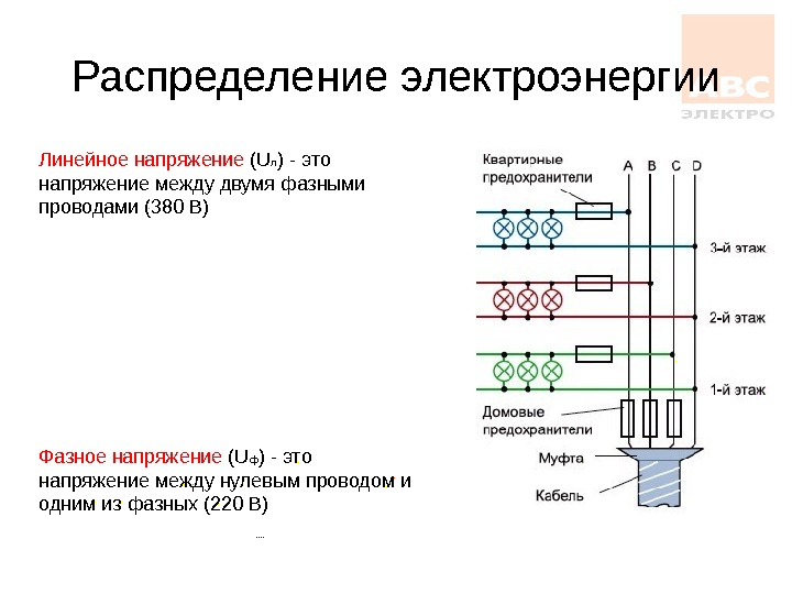
What "three-phase voltage 380V and single-phase voltage 220V"? There is attention. Strictly speaking, in most cases (but not in all), a three-phase household network in the Russian Federation is understood as a 220 / 380V network (occasionally there are household networks 127/220 V and industrial 380/660 V!!!). Incorrect, but occurring designations: 380/220V; 220/127 V; 660/380V!!! So, further we are talking about a conventional 220/380Volt network, to work with the rest - it would be better for you to be an electrician. So for such a network:
- Our home (Russia, and the CIS ...) network is 220/380V-50Hz, in Europe 230/400V-50Hz (240/420V-50Hz in Italy and Spain), in the USA - the frequency is 60Hz, and the ratings are generally different
- At least 4 wires will come to you: 3 linear ("phases") and one neutral (not necessarily with zero potential at all !!!) - if you have only 3 linear wires, it's better to call an electrical engineer.
- 220V is the effective voltage between any of the "phases" = line wire and neutral (phase voltage). Neutral is not zero!
- 380V is the effective value between any two "phases" = line wires (line voltage)
The DPVA.info project warns: if you have no idea about the safety measures when working with electrical installations (see PUE), it’s better not to start yourself.
- Neutral (of all kinds) does not necessarily have zero potential. The quality of the supply voltage in practice does not meet any standards, but should comply with GOST 13109-97 "Electric energy. Compatibility of technical means. Quality standards electrical energy in power supply systems general purpose" (it's nobody's fault...)
- Circuit breakers (thermal and short circuit) protect the circuit from overload and fire, not you from electric shock
- Grounding does not necessarily have low resistance (i.e. saves from electric shock).
- Points with zero potential can have an infinitely large resistance.
- An RCD installed in a supply panel does not protect anyone who receives an electric shock from a galvanically isolated circuit powered from this shield.
A three-phase circuit is a special case of multi-phase electrical systems, which are a set of electrical circuits in which EMFs of the same frequency operate, shifted in phase relative to each other by a certain angle. Note that usually these EMFs, primarily in power engineering, are sinusoidal. However, in modern electromechanical systems, where frequency converters are used to control actuators, the voltage system is generally non-sinusoidal. Each of the parts of a multi-phase system, characterized by the same current, is called phase those. phase - this is a section of the circuit related to the corresponding winding of the generator or transformer, line and load.
Thus, the concept of "phase" has two different meanings in electrical engineering:
- phase as an argument of a sinusoidally changing quantity;
- phase as an integral part of a multi-phase electrical system.
The development of multiphase systems has been driven historically. Research in this area was caused by the requirements of developing production, and success in the development of multiphase systems was facilitated by discoveries in the physics of electrical and magnetic phenomena.
The most important prerequisite for the development of multiphase electrical systems was the discovery of the phenomenon of rotating magnetic field(G. Ferraris and N. Tesla, 1888). The first electric motors were two-phase, but they had low performance. The three-phase system turned out to be the most rational and promising, the main advantages of which will be discussed below. A great contribution to the development of three-phase systems was made by the outstanding Russian electrical engineer M.O.
source of three phase voltage is three-phase generator, on the stator of which (see Fig. 1) is placed three-phase winding. The phases of this winding are arranged in such a way that their magnetic axes are shifted in space relative to each other by el. glad. On fig. 1, each stator phase is conventionally shown as a single turn. The beginning of the windings is usually denoted by capital letters letters A, B, C, and the ends are respectively capitalized x, y, z. EMF in the fixed stator windings is induced as a result of crossing their turns by a magnetic field created by the current of the rotating rotor excitation winding (in Fig. 1, the rotor is conventionally shown as a permanent magnet, which is used in practice at relatively low powers). When the rotor rotates at a uniform speed, periodically changing sinusoidal EMFs of the same frequency and amplitude are induced in the windings of the stator phases, but differ due to a spatial shift from each other in phase by rad. (see Fig. 2).
Three-phase systems are currently the most widely used. On the three-phase current all large power plants and consumers operate, which is associated with a number of advantages of three-phase circuits over single-phase ones, the most important of which are:
Cost-effective transmission of electricity over long distances;
The most reliable and economical, meeting the requirements of an industrial electric drive, is an asynchronous motor with a squirrel-cage rotor;
The possibility of obtaining a rotating magnetic field using fixed windings, on which the operation of synchronous and asynchronous motors, as well as a number of other electrical devices is based;
Balance of symmetrical three-phase systems.
To consider the most important balance properties three-phase system, which will be proved below, we introduce the concept of symmetry of a multi-phase system.
The EMF system (voltages, currents, etc.) is called symmetrical if it consists of m equal modulo EMF vectors (voltages, currents, etc.) shifted in phase relative to each other by the same angle. In particular, the vector diagram for a symmetrical EMF system corresponding to a three-phase system of sinusoids in fig. 2 is shown in fig. 3.
 |
|
| Fig.3 | Fig.4 |
Of the asymmetric systems, the two-phase system with a 90-degree phase shift is of the greatest practical interest (see Fig. 4).
All symmetrical three- and m-phase (m>3) systems, as well as a two-phase system, are balanced. This means that although in individual phases the instantaneous power pulsates (see Fig. 5, a), changing during one period not only the value, but in general case and sign, the total instantaneous power of all phases remains constant throughout the entire period of the sinusoidal EMF (see Fig. 5,b).
Balance is of the utmost practical importance. If the total instantaneous power were to pulsate, then a pulsating torque would act on the shaft between the turbine and the generator. Such a variable mechanical load would have a detrimental effect on the power generating plant, reducing its service life. The same considerations apply to polyphase motors.
If the symmetry is broken (the two-phase Tesla system, due to its specificity, is not taken into account), then the balance is also broken. Therefore, in the energy sector, they strictly monitor that the load of the generator remains symmetrical.
Connection diagrams for three-phase systems
A three-phase generator (transformer) has three output windings, identical in number of turns, but developing EMF, shifted in phase by 120 °. It would be possible to use a system in which the phases of the generator winding would not be galvanically connected to each other. This so-called disconnected system. In this case, each phase of the generator must be connected to the receiver with two wires, i.e. there will be a six-wire line, which is uneconomical. In this regard, such systems have not received wide application on practice.
To reduce the number of wires in the line, the phases of the generator are galvanically connected to each other. There are two types of connections: into a star and into a triangle. In turn, when connected to a star, the system can be three- and four-wire.
star connection
On fig. 6 shows a three-phase system when connecting the phases of the generator and the load into a star. Here the wires AA', BB' and CC' are line wires.
Linear called the wire connecting the beginning of the phases of the winding of the generator and receiver. The point at which the ends of the phases are connected to a common node is called neutral(in Fig. 6, N and N' are the neutral points of the generator and the load, respectively).
The wire connecting the neutral points of the generator and receiver is called neutral(shown in dotted line in Fig. 6). A three-phase system when connected to a star without a neutral wire is called three-wire, with neutral wire four-wire.
All quantities related to phases are called phase variables, to the line linear. As can be seen from the diagram in Fig. 6, when connected to a star, the line currents and are equal to the corresponding phase currents. If there is a neutral wire, the current in the neutral wire ![]() . If the system of phase currents is symmetrical, then . Therefore, if the symmetry of the currents were guaranteed, then the neutral wire would not be needed. As will be shown below, the neutral wire maintains the symmetry of the voltages on the load when the load itself is unbalanced.
. If the system of phase currents is symmetrical, then . Therefore, if the symmetry of the currents were guaranteed, then the neutral wire would not be needed. As will be shown below, the neutral wire maintains the symmetry of the voltages on the load when the load itself is unbalanced.
Since the voltage at the source is opposite to the direction of its EMF, the phase voltages of the generator (see Fig. 6) act from points A, B and C to the neutral point N; ![]() - phase load voltages.
- phase load voltages.
Line voltages act between line conductors. In accordance with Kirchhoff's second law for line voltages, one can write
| (1) |
| (2) |
It is usually taken into account in calculations ![]() . Then for the case direct phase sequence
. Then for the case direct phase sequence![]() , (at reverse phase sequence phase shifts y and change places). Taking this into account, on the basis of relations (1) ... (3), complexes of linear stresses can be determined. However, with stress symmetry, these quantities are easily determined directly from the vector diagram in fig. 7. Directing the real axis of the coordinate system along the vector (its initial phase is equal to zero), we count the phase shifts of the linear voltages with respect to this axis, and their modules are determined in accordance with (4). So for linear voltages we get:
, (at reverse phase sequence phase shifts y and change places). Taking this into account, on the basis of relations (1) ... (3), complexes of linear stresses can be determined. However, with stress symmetry, these quantities are easily determined directly from the vector diagram in fig. 7. Directing the real axis of the coordinate system along the vector (its initial phase is equal to zero), we count the phase shifts of the linear voltages with respect to this axis, and their modules are determined in accordance with (4). So for linear voltages we get: ![]() ;
; ![]() .
.
Triangle connection
Due to the fact that a significant part of the receivers included in three-phase circuits is unbalanced, it is very important in practice, for example, in circuits with lighting devices, to ensure the independence of the operating modes of individual phases. In addition to four-wire, three-wire circuits also have similar properties when connecting the phases of the receiver into a triangle. But the phases of the generator can also be connected into a triangle (see Fig. 8).
For a symmetrical EMF system, we have
![]() .
.
Thus, in the absence of load in the generator phases in the circuit in Fig. 8 currents will be zero. However, if you swap the beginning and end of any of the phases, then a current will flow in the triangle short circuit. Therefore, for a triangle, it is necessary to strictly observe the order of connecting phases: the beginning of one phase is connected to the end of another.
The connection diagram of the generator and receiver phases in a triangle is shown in fig. 9.
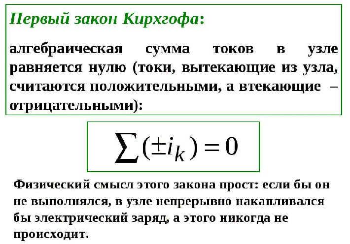
Obviously, when connected to a triangle, the line voltages are equal to the corresponding phase voltages. According to the first Kirchhoff law, the relationship between the linear and phase currents of the receiver is determined by the relations
![]()
Similarly, linear currents can be expressed in terms of phase currents generator.
On fig. 10 shows a vector diagram of a symmetrical system of linear and phase currents. Its analysis shows that with the symmetry of the currents
| . | (5) |
In conclusion, we note that in addition to the star-star and triangle-delta connections considered, the star-triangle and triangle-star schemes are also used in practice.
Literature
- Basics circuit theory: Proc. for universities /G.V.Zeveke, P.A.Ionkin, A.V.Netushil, S.V.Strakhov. –5th ed., revised. -M.: Energoatomizdat, 1989. -528s.
- Bessonov L.A. Theoretical basis electrical engineering: Electrical circuits. Proc. for students of electrical, energy and instrument-making specialties of universities. –7th ed., revised. and additional –M.: Higher. school, 1978. -528s.
Control questions and tasks
A three-phase connection makes it possible to turn on generators and electric motors of increased power, as well as the ability to work with different voltage parameters, it depends on the type of load inclusion in the electrical circuit. To work in three-phase network it is necessary to understand the correlation of its elements.
Elements of a three-phase network
The main elements of a three-phase network are a generator, an electric power transmission line, a load (consumer). To consider the question of what is the linear and phase voltage in the circuit, let's define what a phase is.
A phase is an electrical circuit in a system of multi-phase electrical circuits. The beginning of the phase is the clamp or the end of the conductor of electricity, through which the electric current enters it. Experts have always differed in the number of phases electrical circuits: single-phase, two-phase, three-phase and multi-phase.
The most commonly used three-phase connection of objects, which has a significant advantage over both multi-phase circuits and a single-phase circuit. The differences are as follows:
- lower costs for the transportation of electrical energy;
- the ability to create an EMF for work induction motors- this is the operation of elevators in multi-storey buildings, equipment in the office and in production;
- this type of connection makes it possible to simultaneously use both linear and phase voltage.
What is phase and line voltage?
Phase and line voltages in three-phase circuits are important for manipulations in electrical power panels, as well as for the operation of equipment powered by 380 volts, namely:
- What is phase voltage? This is the voltage that is determined between the beginning of the phase and its end, in practice it is determined between the neutral wire and the phase.
- Linear voltage is when a value is measured between two phases, between terminals of different phases.
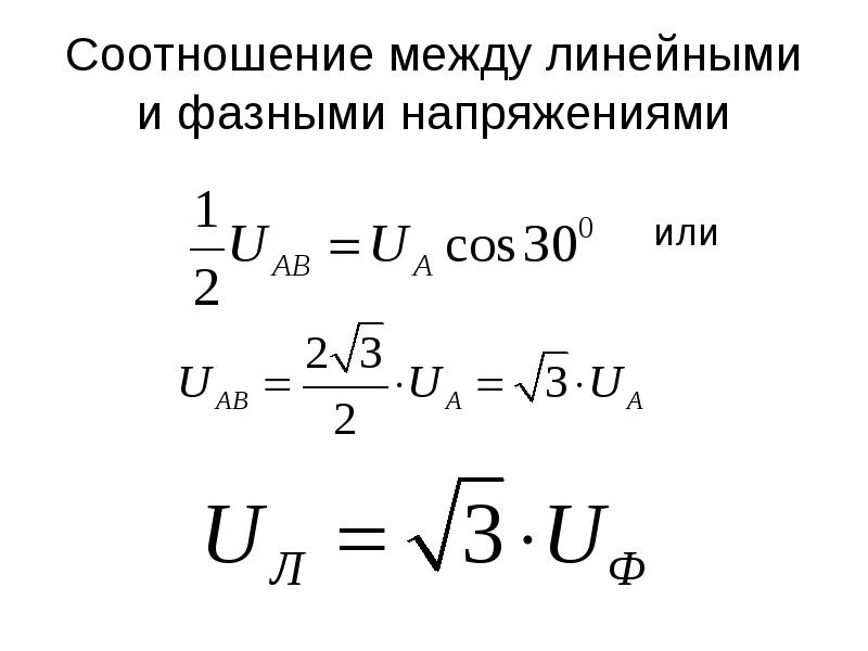
In practice, the phase voltage differs from the linear voltage by 60%, in other words, the parameters of the linear voltage are 1.73 times greater than the phase voltage. Three-phase circuits can have a line voltage of 380 volts, which makes it possible to obtain a phase voltage of 220 V.
What's the Difference?
For society, the concept of "phase-to-phase voltage" is found in multi-apartment, high-rise buildings, when the first floors are provided for office space, as well as in shopping malls when building objects are connected by several power cables three-phase network, which provide a voltage of 380 volts. This type of connection at home ensures the operation of asynchronous lift motors, the operation of an escalator, and industrial refrigeration equipment.
In practice, wiring three-phase circuit quite simple, given that a phase and a zero go to the apartment, and all three phases + a neutral wire go to the office space.
Difficulties linear circuit connections lie in the difficulty of determining during the installation of the conductor, which can lead to an equipment failure. The scheme differs mainly between phase and linear connections, connections of the load windings and the power supply.
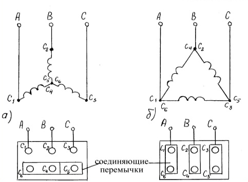
Wiring diagrams
There are two schemes for connecting voltage sources (generators) to the network:
- "triangle";
- "star".
When a star connection is made, the beginning of the generator windings are connected at one point. It doesn't allow for more power. A connection according to the "triangle" scheme is when the windings are connected in series, namely, the beginning of the winding of one phase is connected to the end of the winding of another. This gives the ability to triple the voltage.
For a better understanding of the connection diagrams, experts give a definition of what phase and linear currents are:
- linear current - this is the current that flows in the submarine connection of the source of electrical energy and the receiver (load);
- phase current is the current flowing in each winding of a source of electrical energy or in the load windings.
Linear and phase currents matter when there is an unbalanced load on the source (generator), this is often encountered in the process of connecting objects to the power supply. All parameters related to the line are linear voltages and currents, and those related to the phase are parameters of phase quantities.
From the star connection it can be seen that the linear currents have the same parameters as the phase ones. When the system is symmetrical, the neutral wire is not needed; in practice, it maintains source symmetry when the load is unbalanced.
Due to the asymmetry of the connected load (and in practice this happens with the inclusion of lighting devices in the circuit), it is necessary to ensure independent operation of the three phases of the circuit, this can also be done in a three-wire line when the receiver phases are connected in a triangle.
Important! Specialists pay attention to the fact that when the line voltage decreases, the parameters of the phase voltage change. Knowing the value of the phase-to-phase voltage, you can easily determine the value of the phase voltage.
How to calculate line voltage?
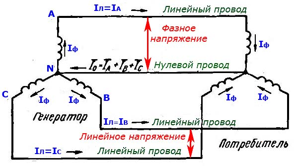
When an extensive system for supplying an object with electricity is being implemented, sometimes there is a need to calculate the voltage between the two wires “zero” and “phase”: IF = IL, which indicates the equality of the phase and linear parameters. The ratio between phase wires and linear wires can be found using the formula:
The finding element of voltage ratios and evaluation of the power supply system by specialists is carried out according to linear parameters, when their value is known. In power supply systems of four wires, 380/220 volts are marked.
Conclusion
Using the capabilities of a three-phase circuit (four-wire circuit), you can make connections in different ways, which makes it possible to widely use it. Experts consider the three-phase voltage for connection to be a universal option, since it makes it possible to connect a high power load, residential premises, office buildings.
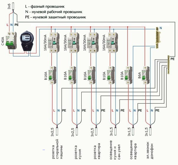
AT apartment buildings the main consumers are household appliances designed for a 220 V network, for this reason it is important to make an even distribution of the load between the phases of the circuit, this is achieved by including apartments in the network according to the chess principle. The distribution of the load of private houses differs, in them it is carried out according to the magnitude of the load on each phase of all home equipment, currents in the conductors passing during the period of maximum switching on of devices.
We advise you to read
 Psychological characteristics of children in adolescence
 Transferring a child to another school - the procedure and necessary documents Whether to transfer a child to another school
, diagnosis, treatment Treatment of urogenital chlamydia") Chlamydia urogenital - description, causes, symptoms (signs), diagnosis, treatment Treatment of urogenital chlamydia
Chlamydia urogenital - description, causes, symptoms (signs), diagnosis, treatment Treatment of urogenital chlamydia The benefits and significance of hydroamino acid threonine for the human body L threonine what

