To Category:
Mobile power plants
Purpose and device of synchronous generators
A synchronous generator consists of two main parts: a fixed stator (armature) with a winding placed in it and a movable (rotating) rotor (inductor) with an excitation winding. The purpose of the excitation winding is to create a primary magnetic field in the generator for induction in the stator winding electromotive force(e.d. e) ... If the rotor of a synchronous generator is brought into rotation at a certain speed V and excited from a direct current source, then the excitation flow will cross the conductors of the stator winding and variables e will be induced in the phases of the winding. d.s. When a load is connected to this winding, a rotating magnetic field will appear in it. This generator stator field will rotate in the direction of rotation of the rotor field and at the same speed as the rotor field, resulting in a total rotating magnetic field.
Rotational speed magnetic field synchronous generator depends on the number of pole pairs. At a given frequency, the greater the number of pairs of poles, the lower the speed of rotation of the magnetic field, i.e. the speed of rotation of the magnetic field is inversely proportional to the number of pairs of poles. So, for example, at a given frequency f = 50 Hz, the speed of rotation of the magnetic field is 3000 rpm for the number of pairs of poles p = 1, 1500 rpm for p = 2V 1000 rpm for p = 3, etc.
The generator stator (Fig. 1, a) consists of a core made of thin sheets electrical steel. To limit eddy currents, the steel sheets are insulated with a 0.08-0.1 mm thick varnish film and firmly pressed into a package, called an active steel package. Figured cutouts are stamped in each sheet of steel, due to which grooves are formed in the package assembled from such sheets, into which the winding fits. The grooves for increasing the electrical strength of the winding and protecting it from mechanical damage are insulated with sheets of electric cardboard with varnished cloth or micanite. The active steel package is fixed in the cast iron or steel frame of the generator.
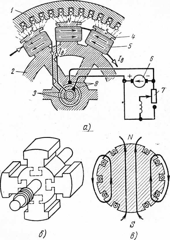
Rice. 1. The device and excitation circuit of a synchronous generator: a - stator, b - salient-pole rotor (without pole winding), c - non-salient-pole rotor; 1 - stator (armature), 2 - rotor (inductor), 3 - contact rings, 4 - pole, 5 - pole inductor coil, 6 - exciter, 7 - shunt regulator, 8 - brushes
The rotor of a synchronous generator can be structurally made salient and non-salient pole.
The salient-pole rotor (Fig. 1, b) has protruding or, as they say, pronounced poles. Such rotors are used in low-speed generators with a rotation speed of not more than 1000 rpm. The cores of the poles of these rotors are usually recruited from sheets of electrical steel 1-2 mm thick, which are firmly fastened into a package with tie rods. On the rotor shaft, the poles are fixed with bolts or with the help of a T-shank of the pole, which is fixed in special grooves milled in the steel body of the rotor.
The excitation winding is wound insulated copper wire corresponding section. In the rotors of synchronous generators intended for operation in electrical installations where diesel engines are used as primary engines, a so-called calming winding is provided. The soothing or, as it is also called, the damper winding is used to calm free oscillations that occur during sudden changes in the operating mode of synchronous generators (sudden load shedding, voltage drop, change in excitation current, etc.), especially in cases where several generators operate in parallel on a common net.
An implicit pole is a rotor that has the form of a cylinder without protruding poles. Such rotors are usually made with two or four poles.
Salient-pole rotors for high-speed machines are not used because of the complexity of manufacturing fastening poles that can withstand large centrifugal forces.
The implicit-pole rotor (Fig. 1, c) consists of a shaft and a steel forging with grooves milled in it, in which the excitation winding is laid. Otherwise, the implicit-pole rotor is structurally made in the same way as the salient-pole one.
The design of the conductors of the rotor winding is selected depending on the type of rotor: for windings of salient-pole rotors, rectangular or round ones are used. insulated wires, as well as bare copper strips, bent on edge and insulated with strips of micanite; The windings of non-salient-pole rotors are made of insulated coils of flat hard-rolled copper placed in insulated grooves of the rotors.
The ends of the rotor winding (inductor) are brought out and connected to slip rings on the rotor shaft. A direct current is supplied to the inductor from some external source. As a source of excitation current for synchronous generators with a power of up to 20 kW, semiconductor rectifiers are used, and for more powerful generators, special DC machines (exciters) are usually placed on a common shaft with the generator rotor or mechanically connected to the generator by means of coupling halves. The exciter is a direct current generator, the power of which, as a rule, is 1-3% of the rated power of the generator fed by it. The rated voltage of exciters is small and for synchronous generators of medium power does not exceed 150 V. D.C for excitation of synchronous generators can be obtained using mercury, semiconductor or mechanical rectifiers. To excite synchronous generators with a power of up to 20 kW, selenium or germanium rectifiers are most often used.
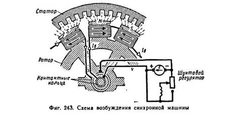
The excitation current in passes from the source to the inductor along the following path: a direct current source - fixed brushes on slip rings, slip rings of the rotor - windings of the poles of the inductor. This path is shown schematically in Fig. 1, a. A synchronous generator has the property of reversibility, i.e. can also work as an electric motor if its stator winding is connected to a three-phase network alternating current.
To Category: - Mobile power stations
9.1. The device and principle of operation of a synchronous generator
Synchronous are called electric cars, the rotational speed of which is connected by a constant ratio with the frequency of the alternating current network in which this machine is connected . Synchronous machines serve as alternating current generators in power stations, and synchronous motors are used in cases where a motor operating at a constant speed is needed. Synchronous machines are reversible, i.e., they can work both as generators and as motors. A synchronous machine switches from a generator mode to a motor mode, depending on whether a rotating or braking mechanical force acts on it. In the first case, it receives mechanical power on the shaft, and gives it to the network electrical energy, and in the second case, it receives electrical energy from the network, and gives mechanical energy to the shaft.
A synchronous machine has two main parts: a rotor and a stator, and the stator does not differ from the stator of an asynchronous machine. The rotor of a synchronous machine is a system of rotating electromagnets that are powered by direct current supplied to the rotor through slip rings and brushes from an external source. In the stator windings, under the action of a rotating magnetic field, an EMF is induced, which is fed to the external circuit of the generator. The main magnetic flux of a synchronous generator, created by a rotating rotor, is excited by an external source - an exciter, which is usually a low-power DC generator, which is installed on a common shaft with a synchronous generator. Direct current from the exciter is fed to the rotor through brushes and slip rings mounted on the rotor shaft. The number of pairs of poles of the rotor is determined by the speed of its rotation. In a multi-pole synchronous machine, the rotor has p
pairs of poles, and the currents in the stator winding also form p pairs of poles of a rotating magnetic field (as in an asynchronous machine). The rotor must rotate with the frequency of rotation of the field, therefore, its speed is equal to:n=60f/p (9.1)
At f = 50Hz and p = 1 n = 3000 rpm.
Modern turbogenerators rotate with this frequency, consisting of a steam turbine and a high-power synchronous generator with a rotor that has one pair of poles.
In hydro generators, the primary engine is a hydraulic turbine, the speed of which is from 50 to 750 revolutions per minute. In this case, synchronous generators with a salient-pole rotor having from 4 to 60 pairs of poles are used.
The rotational speed of diesel generators connected to the primary engine - diesel, is in the range from 500 to 1500 rpm.
In low-power synchronous generators, self-excitation is usually used: the excitation winding is fed by the rectified current of the same generator (Fig. 9.2).
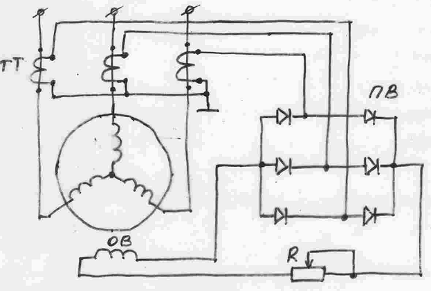
The excitation circuit is formed by CT current transformers included in the generator load circuit, a semiconductor rectifier assembled according to the three-phase bridge scheme, and the excitation winding OB with an adjusting rheostat R.
Self-excitation of the generator occurs as follows. At the moment of starting the generator, due to the residual induction in the magnetic system, weak EMF and currents appear in working winding generator. This leads to the appearance of EMF in secondary windings CT transformers and a small current in the excitation circuit, which enhances the induction of the magnetic field of the machine. generator emf increases until the machine's magnetic system is fully excited.
The average value of the EMF induced in each phase of the stator winding:
Еср = c∙n∙Φ (9.2)
n is the rotor speed;
Φ is the maximum magnetic flux excited in the synchronous machine;
c is a constant coefficient taking into account design features this machine.
Generator terminal voltage:
U = E - I z, where
I - current in the stator winding (load current);
Z is the impedance of the winding (one phase).
To fine-tune the amplitude of the EMF, the magnitude of the magnetic flux is regulated by changing the current in the excitation winding. The sinusoidality of the EMF is provided by giving a certain shape to the pole pieces of the rotor in salient-pole machines. In implicit-pole machines, the desired distribution of magnetic induction is achieved by special placement of the excitation windings on the surface of the rotor.
1. Stator. The stator of a synchronous generator, like other AC machines, consists of a core made of sheets of electrical steel, in the grooves of which an alternating current winding is laid, and a frame - a cast-iron or welded casing from sheet steel.
The stator winding is placed in the grooves stamped on the inner surface of the core. The insulation of the winding is carried out with particular care, since the machine usually has to work with high voltages. Micanite and micanite tape are used as insulation.
In FIG. 240 given the appearance of the stator of a synchronous generator.
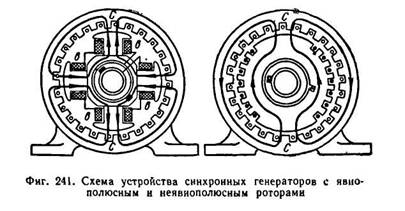
2. Rotor. The rotors of synchronous machines are divided into two types by design:
A) explicitly pole (i.e., with pronounced poles) and
B) implicitly polar (i.e., with implicitly expressed poles).
In FIG. 241 shows diagrams of the device of synchronous generators with salient and non-salient pole rotors.
One or another design of the rotor is dictated by considerations of mechanical strength. In modern generators rotating from high-speed engines (steam turbine), the circumferential speed of the rotor can reach 100-160 m/s (in some cases 170 m/s). Therefore, high-speed generators have a non-salient pole rotor. The speed of rotation of high-speed generators is 3000 rpm and 1500 rpm.
The salient pole rotor is a steel forging.
Poles are attached to the rotor rim, on which excitation coils are put on, connected in series with each other. The ends of the excitation winding are connected to two
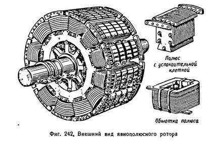
rings mounted on the rotor shaft. Brushes are superimposed on the rings, to which the source is attached. constant voltage. In FIG. 242 shows the appearance of a salient pole rotor. Usually, a direct current generator, sitting on the same shaft with the rotor and called the exciter, gives a direct current to excite the rotor. The exciter power is 0.25-1% of the nominal power of the synchronous generator. Rated voltage of exciters 60-350 V.
In FIG. 243 shows the excitation circuit of a synchronous machine.
Self-excited synchronous generators are also available. A direct current to excite the rotor is obtained using selenium rectifiers connected to the generator stator winding. At the first moment, the weak field of residual magnetism of the rotating rotor induces an insignificant variable e in the stator winding. d.s. Selenium rectifiers connected to AC voltage, give a direct current, which strengthens the rotor field, and the generator voltage increases.
The non-salient pole rotor is made from a whole steel forging, subjected to complex thermal and mechanical processing. As an example, let us give the data of the rotor of a turbogenerator manufactured by the Elektrosila plant with a capacity of 100 thousand kW at n = 3000 rpm. Rotor diameter D = 0.99 m, length l=6.35 m. Circumferential speed of the rotor 155 m/sec. The machined rotor forging weighs 46.5 tons.
In the axial direction along the circumference of the rotor, grooves are milled, where the excitation winding is placed. The winding in the grooves is fixed with metal (steel or bronze) wedges. The frontal parts of the winding are fixed with shroud metal rings.
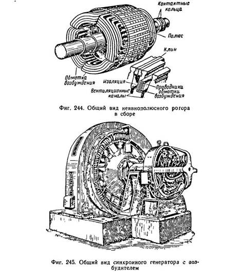
In FIG. 244 shows a general view of the implicitly pole rotor of a turbogenerator in finished form.
When designing electrical machines and transformers great attention designers pay attention to the ventilation of machines. For synchronous generators, air and hydrogen cooling is used.
Air cooling is carried out using fans mounted on a shaft on both sides of the rotor (for generators with a capacity of 1.5 to 50 thousand kW) or located under the machine in a foundation hole (for generators with a capacity of 100 thousand kW).
The masses of cold air entering for ventilation pass through filters to avoid contamination of the machine with dust. With a closed ventilation system, the machine is cooled by the same volume of air. The air, having passed through the machine, is heated and enters the air coolers, then is again forced into the machine, etc. For cooling purposes, the system of ventilation ducts arranged in separate parts of the machine also serves. Most effective way cooling machine is hydrogen cooling. Hydrogen, which has 7.4 times greater thermal conductivity than air, is better at removing heat from hot parts of the machine. Air-cooled friction losses are about 50°/o from
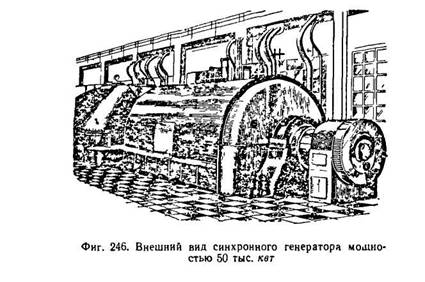
sum of all losses in the car. Hydrogen has a specific gravity 14.5 times less than air. Therefore, the friction against hydrogen decreases sharply. Hydrogen also contributes to the preservation of the insulation and varnish coatings of the machine. Appearance salient-pole synchronous generator with exciter is shown in Fig. 245, and a non-salient pole synchronous generator with a power of 50 thousand kW - in Fig. 246.
Hydrogenerators are driven by hydraulic turbines. These turbines most often have a vertical shaft with a low number of revolutions. The low-speed synchronous generator has a large number of poles and, as a result, large dimensions.
So, for example, a hydrogenerator of the type with a capacity of 50 thousand kW, manufactured by the Elektrosila plant named after. S. M. Kirov, has a total weight of 1142 g, a stator diameter of 14 m, a total height of 8.9 m, the number of poles is 96.
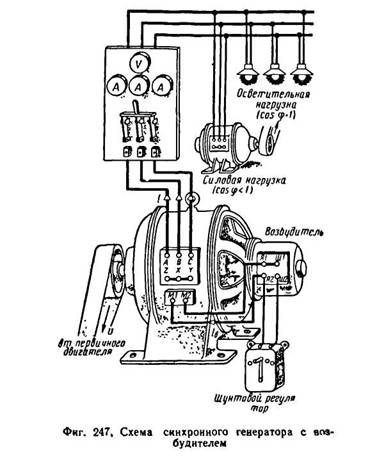
In FIG. 247 shows a diagram of a synchronous generator with an exciter supplying power and lighting loads. In FIG. 248 dan circuit diagram connections of the synchronous generator with the load.
The stator windings of synchronous generators are made in the same way as the stator windings of induction motors.
All six ends of the three-phase windings of the generator are usually displayed on its shield. By connecting the three ends of the windings to one common zero point and bringing the three beginnings of the windings into an external network, we get a star connection of the windings (Fig. 249, a). Connecting the end of the first winding with the beginning of the second, the end of the second with the beginning of the third, the end of the third with the beginning of the first winding and making three taps from the connection points to the external network, we get the connection of the windings in a triangle (Fig. 249, b).
If in the above asynchronous machines the rotor had rotational speed, different from the frequency of rotation of the stator magnetic field, then in synchronous these frequencies are equal to each other.
Synchronous machines can operate as both generators and motors.
Depending on the type of drive, synchronous generators have also received their names.
Turbogenerator, for example, is a generator driven by a steam turbine, a hydro generator rotates a water wheel, and a diesel generator is mechanically connected to an internal combustion engine.
Synchronous motors are widely used to drive powerful compressors, pumps, fans.
Synchronous micromotors are used to drive the tape drive mechanisms of recording devices, tape recorders, etc.
6.1. DESIGN AND PRINCIPLE OF OPERATION OF A SYNCHRONOUS GENERATOR
The stator of a synchronous machine does not differ in design from the stator of an induction motor. Three-phase, two-phase or single-phase windings are placed in the stator slots.
A noticeable difference is the rotor, which is fundamentally a permanent magnet or an electromagnet.
This imposes special requirements on the geometric shape of the rotor. Any magnet has poles, the number of which can be two or more.
On fig. 6.1.1 shows two designs of generators, with a low-speed and high-speed rotor.
High-speed are, as a rule, turbogenerators. The number of pairs of magnetic poles they have is equal to one. In order for such a generator to produce an electric current of standard frequency f = 50 Hz, it must be rotated with a frequency
In hydroelectric power plants, the rotation of the rotor depends on the movement of the water flow. But even with slow rotation, such a generator should produce electricity standard frequency f = 50 Hz.
Therefore, for each hydroelectric power plant, its own generator is designed, for a certain number of magnetic poles on the rotor.
As an example, let us give the parameters of a synchronous generator operating at the Dnieper hydroelectric power station.
The water flow rotates the generator rotor with a frequency of n = 33.3 rpm. Given the frequency f = 50 Hz, we determine the number of pairs of poles on the rotor:
The principle of operation of a synchronous generator is based on the phenomenon of electromagnetic induction. A rotor with magnetic poles creates a rotating magnetic field, which, crossing the stator winding, induces an EMF in it. When connected to a load generator, the generator will provide AC power.
6.2. EMF OF SYNCHRONOUS GENERATOR
As shown above, the magnitude of the EMF induced in the stator winding is quantitatively related to the number of turns of the winding and the rate of change of the magnetic flux:
Turning to the effective values, the EMF expression can be written as:
where n is the generator rotor speed,
Ф - magnetic flux,
c is a constant factor.
When the load is connected, the voltage at the generator terminals changes to varying degrees. So, increasing the active load does not have a noticeable effect on the voltage. At the same time, inductive capacitive load affect the output voltage of the generator. In the first case, an increase in load demagnetizes the generator and reduces the voltage, in the second case, it is biased and the voltage rises. This phenomenon is called anchor reaction.
To ensure the stability of the generator output voltage, it is necessary to regulate the magnetic flux. When it is weakened, the car must magnetize, with an increase - demagnetize. This is done by regulating the current supplied to the excitation winding of the generator rotor.
6.3. SYNCHRONOUS MOTOR
6.3.1. DESIGN AND OPERATING PRINCIPLE
The design of a synchronous motor is the same as that of a synchronous generator.
When current is applied to three-phase winding stator, a rotating magnetic field arises in it. Its rotation frequency is determined by the formula:
where f is the frequency of the mains current,
p is the number of pairs of poles on the stator.
The rotor, which is often an electromagnet, will strictly follow the rotating magnetic field, i.e. its rotational speed n 2 \u003d n 1.
Consider the principle of operation of a synchronous motor on the following conditional model (Fig. 6.3.1.). Let the stator magnetic field be modeled by a system of rotating magnetic poles N - S.
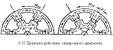
The motor rotor is also a system of electromagnets S - N, which are "linked" to the poles on the stator. If there is no load on the motor, then the axes of the stator poles will coincide with the axes of the rotor poles ( = 0).
If a mechanical load is connected to the rotor, then the axes of the stator and rotor poles can diverge by a certain angle.
However, the "magnetic coupling" of the rotor with the stator will continue, and the rotor speed will be equal to the synchronous frequency of the stator (n 2 = n 1). At high values, the rotor may come out of the "clutch" and the engine will stop.
The main advantage of a synchronous motor over an asynchronous one is the provision of a synchronous rotor speed with significant load fluctuations.
6.3.2. SYNCHRONOUS MOTOR STARTING SYSTEM
As we have shown above, the synchronous rotation of the rotor is provided by "magnetic coupling" of the rotor poles with the rotating magnetic field of the stator.
At the first moment of starting the engine, the rotating magnetic field of the stator occurs almost instantly. The rotor, having a significant inertial mass, cannot immediately come into synchronous rotation. It must be "overclocked" to subsynchronous speed by some additional device.
For a long time, the role of an accelerating motor was played by an ordinary asynchronous motor, mechanically connected to a synchronous motor.
The rotor of a synchronous motor is driven to subsynchronous speed. Further, the engine itself is drawn into synchronism.
Usually power starting motor is 5-15% of the power of a synchronous motor. This allows the synchronous motor to be started only at idle or with a small load on the shaft.
The use of a starting motor with sufficient power to start a synchronous motor under load makes such an installation cumbersome and expensive.
Recently, the so-called asynchronous start system synchronous motors. For this purpose, rods are hammered into the pole pieces, resembling a short-circuited winding of an induction motor (Fig. 6.3.2.1).
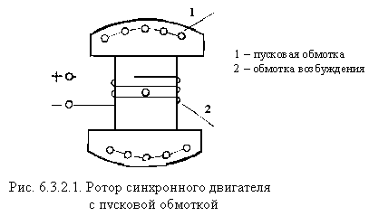
During the initial start-up period, the synchronous motor operates as an asynchronous motor, and subsequently as a synchronous motor. For safety reasons, the excitation winding is short-circuited in the initial period of the start-up, and at the final one it is connected to a direct current source.
6.4. JET SYNCHRONOUS ENGINE
In laboratory practice, in everyday life and in low-power mechanisms, the so-called reluctance synchronous motors.
They differ from conventional classic machines only in the design of the rotor. The rotor here is not a magnet or an electromagnet, although in shape it resembles a pole system.
The principle of operation of a synchronous reluctance motor is different from that discussed above. Here, the operation of the motor is based on the free orientation of the rotor in such a way as to provide the stator magnetic flux with the best magnetic conductivity (Fig. 6.4.1).
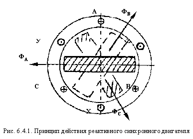
Indeed, if at some point in time the maximum magnetic flux is in phase A - X, then the rotor will take a position along the FA flux. After 1/3 of the period, the maximum flow will be in phase B - U. Then the rotor will turn along the PV flow. After another 1/3 of the period, the rotor will be oriented along the flow. FS. So continuously and synchronously the rotor will rotate with the rotating magnetic field of the stator.
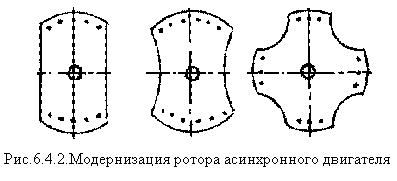
In school practice, sometimes, in the absence of special synchronous motors, there is a need for synchronous transmission.
This problem can be solved with the usual induction motor, if we give the rotor the following geometric shape (Fig. 6.4.2).
6.5. STEP MOTOR
This type of motor is a direct current machine, although its principle of operation is similar to that of a synchronous reluctance motor.
As can be seen from fig. 6.5.1, the motor stator has six pairs of protruding poles.
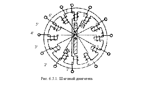
Each two coils located on opposite poles of the stator form a control winding that is connected to the DC network. The rotor is bipolar.
If you connect pole coils 1 - 1 "to a direct current source, then the rotor will be located along these poles. If you use the coils of poles 2 - 2", and de-energize the coils of poles 1 - 1 ", the rotor will turn and take a position along the poles 2 - 2". The same rotation of the rotor will occur if the coils of poles 3 - 3 are connected to the network. So, in steps, the rotor will "follow" its control winding.
The advantage of stepper motors is that they have absolutely no "self-propelled". They turn and are strictly fixed in increments proportional to the number of poles on the stator. This quality makes it indispensable in highly precise mechanisms (for driving clocks, mechanisms for supplying nuclear fuel in reactors, in CNC machines, etc.).
Stepper motors are controlled using various electronic devices (Schmidt triggers, etc.).
6.6. COLLECTED AC MOTOR
Brushless asynchronous and synchronous motors, with many positive qualities, have significant drawbacks. They do not allow sufficiently smooth and economical rotation control.
This gap is partially filled by AC collector motors.
Collector motors are single-phase and three-phase.
The rotor of a single-phase collector motor is made in the form of a cylinder with phase windings, the stator is salient-pole.
Since the winding of the stator poles, connected to the AC network, creates a pulsating magnetic field, all elements of the magnetic circuit of the machine are recruited from separate sheets of electrical steel.
The torque in a single-phase collector motor is created by the interaction of currents in the rotor winding with the magnetic flux of the poles. On fig. 6.6.1 - shows the connection diagram of the collector motor to the network.
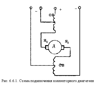
Collector motors can be operated both from the AC network and from the DC network. This circumstance served to give them the name of universal collector engines. Collector motors are widely used to drive sewing machines, vacuum cleaners, etc.
Synchronous are called electrical machines, the rotational speed of which is connected by a constant ratio with the frequency of the alternating current network in which this machine is included. . Synchronous machines serve as alternating current generators in power stations, and synchronous motors are used in cases where a motor operating at a constant speed is needed. Synchronous machines are reversible, i.e., they can work both as generators and as motors. A synchronous machine switches from a generator mode to a motor mode, depending on whether a rotating or braking mechanical force acts on it. In the first case, it receives mechanical energy on the shaft, and gives electrical energy to the network, and in the second case, it receives electrical energy from the network, and gives mechanical energy to the shaft.
A synchronous machine has two main parts: a rotor and a stator, and the stator does not differ from the stator of an asynchronous machine. The rotor of a synchronous machine is a system of rotating electromagnets that are powered by direct current supplied to the rotor through slip rings and brushes from an external source. In the stator windings, under the action of a rotating magnetic field, an EMF is induced, which is fed to the external circuit of the generator. The main magnetic flux of a synchronous generator, created by a rotating rotor, is excited by an external source - an exciter, which is usually a low-power DC generator, which is installed on a common shaft with a synchronous generator. Direct current from the exciter is fed to the rotor through brushes and slip rings mounted on the rotor shaft. The number of pairs of poles of the rotor is determined by the speed of its rotation. In a multi-pole synchronous machine, the rotor has p pairs of poles, and the currents in the stator winding also form p pairs of poles of a rotating magnetic field (as in an asynchronous machine). The rotor must rotate with the frequency of rotation of the field, therefore, its speed is equal to:
n=60f/p (9.1)
At f = 50Hz and p = 1 n = 3000 rpm.
Modern turbogenerators rotate with this frequency, consisting of a steam turbine and a high-power synchronous generator with a rotor that has one pair of poles.
In hydro generators, the primary engine is a hydraulic turbine, the speed of which is from 50 to 750 revolutions per minute. In this case, synchronous generators with a salient-pole rotor having from 4 to 60 pairs of poles are used.
The rotational speed of diesel generators connected to the primary engine - diesel, is in the range from 500 to 1500 rpm.
In low-power synchronous generators, self-excitation is usually used: the excitation winding is fed by the rectified current of the same generator (Fig. 9.2).
The excitation circuit is formed by CT current transformers included in the generator load circuit, a semiconductor rectifier assembled according to the three-phase bridge scheme, and the excitation winding OB with an adjusting rheostat R.
Self-excitation of the generator occurs as follows. At the moment of starting the generator, due to the residual induction in the magnetic system, weak EMF and currents appear in the working winding of the generator. This leads to the appearance of EMF in the secondary windings of CT transformers and a small current in the excitation circuit, which enhances the induction of the magnetic field of the machine. The generator emf increases until the machine's magnetic system is fully excited.
The average value of the EMF induced in each phase of the stator winding:
Еср = c∙n∙Φ (9.2)
n is the rotor speed;
Φ is the maximum magnetic flux excited in the synchronous machine;
c is a constant coefficient that takes into account the design features of this machine.
Generator terminal voltage:
U = E - I z, where
I - current in the stator winding (load current);
Z is the impedance of the winding (one phase).
To fine-tune the amplitude of the EMF, the magnitude of the magnetic flux is regulated by changing the current in the excitation winding. The sinusoidality of the EMF is provided by giving a certain shape to the pole pieces of the rotor in salient-pole machines. In implicit-pole machines, the desired distribution of magnetic induction is achieved by special placement of the excitation windings on the surface of the rotor.
We advise you to read
, diagnosis, treatment Treatment of urogenital chlamydia") Chlamydia urogenital - description, causes, symptoms (signs), diagnosis, treatment Treatment of urogenital chlamydia
Chlamydia urogenital - description, causes, symptoms (signs), diagnosis, treatment Treatment of urogenital chlamydia The benefits and significance of hydroamino acid threonine for the human body L threonine what
 To wait or not to wait for a guy from the army For what reason can they be commissioned from the army
 Baked apples with cottage cheese Baked apples with cottage cheese

