Of all the electrical switching devices encountered modern man, the most common - sockets and switches. Due to the ongoing transition of the planet to energy-saving lamps (gas-discharge and diode), the current load on the switches is constantly decreasing.
But the load on the sockets, on the contrary, increases. Operation of powerful vacuum cleaners, washing machines with the function of heating water, irons, electric kettles etc. leads to the fact that the consumed current reaches values of several tens of amperes. And all this load falls on the sockets.
The main function of sockets is to create a reliable contact with the plug of the connected device. No matter how powerful the device is, the place of contact between the terminal and the plug should not heat up, let alone melt. Otherwise, a fire with all its terrible consequences is possible.
In addition, the design of the socket must exclude accidental contact with current-carrying wires and parts. The conclusion from all of the above is that in order to avoid all sorts of troubles, you need to purchase high-quality sockets and connect them in compliance with the necessary rules. In this article, we will look at how to execute hosted in a single module.
Electrical outlet device
The market offers a huge number of outlets that differ in design, appearance and color. There are stationary models: internal, designed for embedding into the wall, and overhead, mounted on the wall.
There are remote units with a switch - a pilot extension cord for connecting a computer, for example. Sockets also differ in the degree of protection against dust and moisture - in accordance with the IP standard. The level of protection against moisture, for example, may even provide for the possibility of immersing the switched on device in water.
For normal conditions in which the vast majority of users live, the quality of contact between the current-carrying wires and the socket terminals is of the greatest importance. It is in this place that the problem most often occurs in the form of poor contact, heating and reflow.
The most common type connecting wires to sockets- screw terminals. The wire cores are pressed against the terminals with screws. The advantage of this type of connection is that a large pressing force is provided on the core to the terminal, which ensures a fairly good electrical contact.
For greater reliability, it is advisable to put two washers under the bolt head. One is the usual flat, the other is spring (grover washer). In this case, spontaneous unscrewing of the screw and loosening of the clamp will not occur.
Ordinary sockets are connected with two wires - phase and zero. But there are sockets with three terminals, one of which is connected to the ground wire. They are called - "sockets with grounding". The plug included in such a socket, in addition to two ordinary pins, also has a terminal that is connected to the ground terminal of the socket.
The number of household electrical appliances in our homes is increasing every year. Everyone wants to have an electric kettle, microwave oven, coffee maker, etc. at home. But not always for all these devices there are enough installed sockets. And even if there are enough of them, then they are not located where necessary.
You have to use these devices one by one, removing them from the sockets or using a kind of extension cords, which is not very convenient. In this case, the easiest way out is to perform between themselves. Install two or three sockets in one place and connect them in parallel.
Parallel connection of sockets in a modular block
There is a socket module in which parallel connection sockets. Of course, they are all sold already assembled, but I would like to disassemble and explain the connection principle itself. To connect the wires to the socket block, you must first remove the cover by unscrewing the screws securing it.

If you now look closely at the design of the socket, you can see that the terminals of the receiving holes are connected in parallel. To supply voltage to all terminals, it is enough to connect the wires to any pair of them.
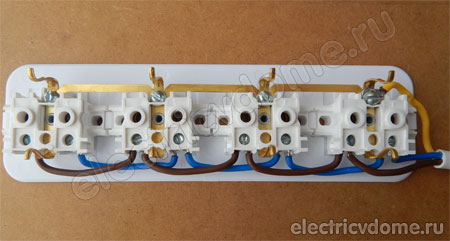
Let's take a look at how the wires are connected in such a block. We remove all installed wires and for clarity we take multi-colored ones: brown wire - phase, blue wire - zero.

As you can see in the photo, the block consists of four outlets. Each outlet, like any other, has two contacts. Our task is to connect all the sockets so that they work independently of each other, and this can be done by applying.
In fact, everything is quite simple. Let's assume that the right socket contact is zero, the left phase. We connect a blue wire to the right contact of each socket: from the first to the second, from the second to the third, etc. On the left contact of each socket, we similarly connect the brown wire.

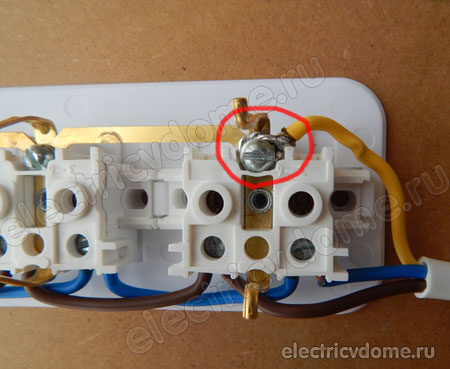
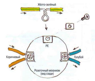
This socket module has grounding contacts. The ground wire is connected to them with a bolt and washer, so we will twist it with a ring. We will leave the phase and neutral wires straight, since the wires are fixed in the socket contacts themselves with the help of a pressure plate. When connecting, you need to pay attention to the color of the wire insulation.
A yellow wire is usually connected to the ground terminal, blue and brown to the "phase" and "zero". If the ground wire is stranded (consists of many thin wires), then after folding it into a ring, it is advisable to irradiate it. Otherwise, individual wires may stick out from under the screw washer, and the contact will not be complete. The same applies to the "phase" and "zero" wires.
After removing the insulation (approximately 1 cm long), they must be twisted with pliers and irradiated. When buying modular type sockets, as in the example, it is advisable to check the correct connection and reliability of the connection of the contacts before installation. If necessary, the contacts must be tightened.
Having connected the cores to the terminals, it is advisable to attach the wire at the branching point to the socket body - so that it cannot be pulled out. The method of fastening may be different depending on the design of the outlet. You can use a band-aid or a metal plate with holes around the edges. Some sockets have in their configuration a special clamp for this.
In conclusion, you need to check the correctness of the connection by connecting some electrical appliance with a Euro socket to each pair of receiving sockets. At the same time, the ease of on / off is also checked.
If the plug is inserted and removed with excessive force, you need to bend the grounding contacts protruding from the sides. Before installing the cover, you need to cut a side hole for the wire in it. Usually there is already a basting for it in the lid. It is only required to cut out the marked place and, having put the cover in place, screw it on.
Connecting sockets with a loop
Sometimes it becomes necessary to install an additional outlet by connecting it in parallel to an already installed one. Such a connection scheme is more economical than laying a separate wire.
In this case, the wires from the new outlet must be connected to the terminals installed outlet so that "phase" is connected to "phase", and "zero" - to "zero". Usually in sockets, the phase wire is located on the right.
When connecting electrical devices and connecting wires to each other, you need to make sure that the metal of the connected wires is the same. Those. copper core should be connected to copper, and aluminum to aluminum.
Upon contact of copper with aluminum, the metals are oxidized (in the form of a white coating), which ultimately leads to a breakdown in contact. If it is impossible to ensure the uniformity of the metal of the connected cores, it is necessary to irradiate the contact ends of the wires (this will not save from oxidation, but will slow down its process). We will talk about how to perform a loop in the next article.
Related content on the site:
1. Working with outlet boxes
At installation and connection of sockets, the ends of the wires inserted into the branch or installation boxes, after laying, are cut off with a minimum margin of 120 ... 150 mm, which in theory should provide convenient reconnection and replacement of the socket / switch or connection to the block. In fact, the length of the wire left in the box depends on many factors, so at the stage of wiring, leave the ends of the wire in boxes with a length of at least 200 mm. It is always easier to cut off the excess than to build up or redo everything from the beginning.
It must be borne in mind that single-core copper wires are quite rigid, and the thicker the wire, the stiffer it is. Therefore, for laying a rather rigid wire with a cross section of 2.5 mm2 in a box under the socket mechanism, it can be convenient to form something like a loop out of it, namely the end of the wire with a clear bend in the middle. Why is the end of the wire about two diameters of the box left in the box, which is folded in half, so that the bend is inside the box. After biting to the desired length, the end of the wire is pulled out a little, trying not to straighten the formed bend too much, stripped and inserted into the mechanism. Then the mechanism is inserted into the box, while the wire folds quite easily along the already formed bend, which plays the role of a hinge.
In more complex cases of switching wires in a box, a margin of approximately 150 ... 200 mm of each wire is left. Then, bending, but not biting the wire, simulate its laying in a box along with the equipment that will be there. Simulate two cases: the connected state of the equipment (i.e., the equipment is not in the box) and the fully assembled state (i.e., the equipment is installed in the box). Mark with a felt-tip pen on the wires the places where they will need to be bent or bitten. Then bite, clean the ends and mount the equipment.
Pay attention to some features.
You should always try to pass the wire under the mechanism of the socket, switch or under the terminal block, there is always a margin left there (there is usually a lot of space under the mechanism, if it is not enough, use a deeper box).
First, the wires are attached to the mechanism, and then the mechanism is carefully installed in the box.
Wires and cables are inserted into the box so that the cut-out section of the dividing base or the second and third layers of insulation does not reach the point of entry into the box by at least 10 ... 15 mm.

The conductor strands are connected in boxes in any of the ways described in this book, and the exposed areas are insulated with insulating tape or heat-shrinkable tubing.
They try to lay the insulated ends of the conductors in boxes in such a way that they do not touch each other.
The ends of cables and wires at the entrance to the box are fixed with a plastic bracket on the wall at a distance of no more than 50 mm from the box. Usually the wire is fixed in the stub every half a meter with a small amount of alabaster. It must be understood that this method is used only to fix the wire before plastering the stab. Near the box, the wire must not only be fixed, but also securely fixed for any type of wiring, since the end emerging from the box will be subjected to serious mechanical stress when the mechanism is connected, which the alabaster latch may not withstand. This task is perfectly handled by a standard plastic bracket.

The wire should be tried to be inserted into the box with the location of the input terminals of the socket or switch. Note that if the socket mechanism can be installed in two ways - terminals up and terminals down, which does not affect appearance sockets, the switch mechanism is installed in only one way. If it turns out that the wire entry is on an awkward side for connecting to the mechanism, leave the longer end of the wire in the box to form wire loops that provide an easy connection.
Sometimes it happens that the frame of the installation product does not fit snugly against the wall after installation. This is usually caused by the fact that the installation box is not fully seated in the place intended for it. If the box is plastic - it must be cut, if it is metal - bend it with a hammer.
For hollow (plasterboard) walls, boxes are produced that have special fasteners, although there are also universal boxes suitable for any type of wall.
2. Connecting a protective neutral conductor to sockets connected by a loop
Connecting sockets
PUE: “In group networks, the connection of protective contacts of sockets and / or protective (grounding) contacts of lighting devices of protection class I must be carried out using branches. Loop connection is not allowed.
This requirement is due to the fact that if the socket or lighting device is damaged, the protective circuit for the rest of the electrical consumers of this group network may be violated. Zero Gap protective conductor when connected by a loop is not allowed. If a screw connection is used on the socket mechanism to connect the protective neutral conductor, then it would seem that it is possible to carry out installation without breaking it, but only removing part of the insulation from the wire at the junction, making a loop at this place with round-nose pliers and placing this loop under the screw.
Alas, this is prohibited, because it is not a branch. A good option for connecting a protective neutral conductor (PE) to sockets connected by a loop is to make branches on the protective neutral conductor PE passing through the installation box using special connectors such as Werit, Scotchlok or Wago and insert the conductors of these branches into socket mechanisms. Although it seems to me that it is a great slyness to consider a conductor inserted into clamps like Werit or Wago as an inseparable one. An honest branch from a non-breakable conductor can only be obtained using Scotchlok™ style mortise connectors.

In this case, it turns out that the PE conductor is connected to the sockets using branches, and the phase and working zero are in series, i.e., with a loop. In the figure, for simplicity, breaks in the N and L conductors are not shown.


In this case, the connector clamp can be placed in the installation box under the socket mechanism, where free space must be provided for this. That is, when choosing sockets and installation boxes, it must be taken into account that the depth of the box must be greater than the height of the mechanism by at least the thickness of the clamp.

3. Installation and connection of sockets
The mechanism of the switch or socket is attached to the box either with two self-tapping screws, or with the help of spacer legs. For the last mounting option, a special corrugation is made on the inner wall of the box. It should be noted that fastening the mechanism in plastic boxes with the help of spacer legs is not as reliable as with self-tapping screws, and requires skill when installation of sockets. As a rule, round boxes with a diameter of 68 mm are used to fasten mechanisms with the help of spacer legs. First, the screws are unscrewed from the spacer legs so that the switch or socket mechanism can be inserted into the box. When the screws are tightened, the legs move apart and fix the switch or socket in the box. The screws are turned one by one, avoiding distortion, and with such force as not to split the fragile plastic base of the mechanism.
The main advantage of installation with spacer tabs is that the requirements for the accuracy of the installation of the box in the wall and especially for the azimuth orientation of the box are reduced. But this medal also has a downside: it is very easy to install a mechanism with an azimuthal skew, which is very ugly and completely unacceptable.
In old houses, there are still Soviet sockets and switches, fixed with spacer legs in steel boxes with smooth inner walls. Most of us who have lived in such houses must remember that the sockets and switches held very poorly in the boxes. The point was not at all in the unsuccessful method of fastening, but in the ugly quality of the manufacture of the fastening mechanism and the box itself. Modern boxes and mechanisms of sockets and switches, especially world brands, are made much better. Unfortunately, it is only necessary to replace old mechanisms with modern devices together with boxes.
If it is planned to repair the apartment with the replacement of electrical wiring and hanging additional outlets, then you need to immediately decide how many of them will be, and where they will be located, in what way they can be connected to the shield, whether it will be open wiring or closed, what types of electrical outlets decided to install. All this is actually very important. And you can’t do without a preliminary discussion with your family or a specialist. The socket connection scheme must be carefully thought out, since after the work is completed it is not always possible to change or fix anything.
Wiring diagrams
There are parallel circuits for connecting electrical outlets, serial and stub. Traditionally, electrical wires descend from the ceiling down the wall. In this case, it is enough just to guess exactly where the wire is located in the wall. However, this option involves additional connections in junction boxes, which reduces the reliability of the power grid. Such a scheme is called parallel. Our grandfathers also knew how to connect an outlet, with this connection method.


It should be understood that electrical outlets in the same group can only be connected in parallel. But there are two kinds of their "parallels". With one method, the wires are connected in junction boxes, and with the other, sockets are connected with a loop between them. With this connection, you can save on wires and boxes. A daisy chain is used for a group of electrical outlets in close proximity. The wires between them run horizontally. And only one electrical wire descends from the ceiling to the first outlet.
Serial connection method allows you to open electrical network. For example, when there is a power outage or one or several electrical outlets that are currently unnecessary. In this case, you need to know how to connect the switch; from the outlet to it, the connection goes in series.
Double and triple sockets
The electrical outlets are connected after the place has been chosen for it, the wire has been laid there and the socket boxes have been mounted. After that, the machine is turned off or the plugs are unscrewed to relieve the voltage, and check its absence. Then the wire is stripped. And only after that the connection is made. The cores can simply be brought into the terminals or their ends can be bent in the form of rings of small diameter. If a grounded socket is connected, then the third, grounding core must be connected to a specific terminal. Before that, you should make sure that it is the grounding one. At the last stage, the electrical outlet is installed in the socket and the cover is screwed on.
When connecting a double or triple electrical outlet, it will be correct to connect the cores to different plates that conduct current, and not to one. The question of how to connect a grounded outlet can be answered - similarly to that described above. The ground wire is also connected to the ground terminal.
For three-phase socket lay a separate four-wire wire and additionally install a circuit breaker.
When the question arises of which way to connect sockets to choose. You can connect each outlet to a separate power line, or you can connect several outlets to one line by connecting the outlets with a loop. In this article, we will consider cases when it is possible to apply the method daisy-chained socket connections. We also give the advantages and disadvantages of this method of connecting sockets.
The connection of sockets with a loop involves the connection of several socket outlets to one electrical wiring line. In this case, the wiring line is connected to the first outlet, from the first outlet the wire goes to the second, from the second to the third, and so on. A significant drawback of this method of connecting sockets is its unreliability. Let's give an example that will show what the unreliability of this connection method is.
Three sockets are connected by a loop, while from the first socket there is a wire to the second, and from the second to the third. The sockets have two pairs of contacts, that is, the supply wire is connected to one of the contacts, and the wire that feeds the next socket is connected to the second socket contacts.
You turn on a heater in the third outlet, which draws a current of ten amperes. In this case, the current flows along the path: the third outlet - the second outlet - the first outlet - the electrical wiring line. The first and second sockets remain free, that is, they are not currently included in them. household electrical appliances. But a current flows through them, which consumes an electrical appliance connected to a third outlet.
If you plug another heater into the second outlet, then a total current will flow through it, that is, twenty amperes. In addition, this current will flow through the first outlet. As a rule, the socket outlet is designed for rated current at 16 amps. Consequently, the first and second sockets may be damaged, since a current will flow through them, which is higher than nominal value.
Based on the foregoing, we can conclude that the use of the method of connecting sockets with a loop is allowed in the case when the total load of the connected sockets is small, that is, not higher than the nominal value of one of the sockets.
For example, in one room it is necessary to install six sockets for connecting computers. In this case, the total power consumption is small. That is, with the simultaneous operation of all computers, the load current that flows through all sockets will be small. In this case, the advantage of this method of connecting sockets is to save money on wiring, since to power the sockets it is enough to draw one line of wiring, install one, and also power the rest of the sockets from the first. But at the same time, it should be remembered that the reliability of the wiring diagram is reduced.
If it is necessary to install several sockets into which powerful household electrical appliances will be connected, then the connection of each socket should be made to separate electrical wiring lines. In this case, more money will be spent, but the socket connection scheme will be reliable.
Connecting an outlet is a very simple, but responsible procedure. This article is for those who are doing it for the first or second time. Although it may be of interest to an experienced amateur electrician, for example, with its step by step instructions and photographs. If you have any questions or comments, leave them in the comments, I will be happy to answer.
Scheme
Options for connecting sockets: parallel and serial.
The socket can be connected both to the shield and in a row with existing sockets. By connecting it directly to the shield, we free ourselves from some of the problems (this method is called "parallel"). But, as a rule, you have to connect them into one loop (this method is called "serial"), and here you need make sure that the wire from the shield is thick enough. The wire in the example below is rated for up to 15 amps. Wiring diagrams are trivial and we present them here only for general information. The PE ground wire is drawn with a broken line.
In the diagram, the right two sockets are considered connected in parallel. Left sockets - in series. Connecting sockets in a loop (“in series”) is absolutely not scary for connecting lighting fixtures, irons and kettles, drills and fans, refrigerators and vacuum cleaners. If you also connect a TV, computer, video player, printer, Wi-Fi access point, satellite dish receiver to this cable, then you are guaranteed completely unexpected failures and even equipment breakdowns. Sockets are divided into several types: built-in, overhead, outdoor, with and without a grounding contact, with and without shutters, sockets for three-phase network… Wikipedia has an excellent article on this topic, which not every specialist will read in its entirety. Here we will show how to connect a double socket. We connect the socket to the open wiring in the country. In those days when the dacha was being built, there was no talk of any "earth" wires, so we use a simple double socket without a ground contact and without curtains. In our opinion, curtains only complicate life without increasing safety at all. They are needed in that short period of life when you have small children. But for this time it is necessary (even necessary!) To buy special plastic plugs. This is how a double socket looks disassembled on the floor:

Training
The ground wire is always yellow-green. Never use it for other purposes. Phase wire - white, red, brown; zero - blue, black. Unfortunately, some electricians adhere to other traditions. In old Soviet houses, in general, all the wires are white. It will be convenient for you if the zero and phase wires are located the same on all sockets. For example, the neutral wire is always at the bottom or left.
It is customary to place the socket so that the contacts are at the bottom. This makes some sense: in the event of a roof leak, the water flowing down the wires will collect in the form of drops at the bend below and will not immediately reach the live contacts.
We start connecting the outlet with cooking:
- tools (screwdriver, indicator screwdriver, long-nose pliers, wire cutters, possibly a crimping tool (crimper, press tongs), building level);
- consumables: suitable wires, terminal blocks, possibly sleeves or cable terminals;
- flashlight.

Choose the exact location of the outlet. It is impossible to solve it scientifically, only for reasons of convenience and possible movements of the sofa, table, cabinet ... We mark out places for fixing screws. Building level - to help. However, you can get by with a modern smartphone with a suitable downloaded program. 
In our case, it is now necessary to cut the wire in the right place. We estimate the length for bending and 1 cm for the terminal. We have a snack. (Measure seven times - cut one!) We clean the wire from the upper braid, We clean the ends of the wires by 1 cm. (It is wrong in the photo - the ends are too short.) It is quite convenient to do this with a clerical knife. You can extend the blade just the thickness of the insulation and do not damage the wire. A special tool, of course, is convenient, but it is necessary only for professionals for daily work.

Wire stripping with a special tool
We bend. With soft stranded wire it is more convenient to work with a thick single-core - more reliable. The example uses copper wire with a section of 2.5 square millimeters.

Connection
We fasten the socket to the wall, insert the wires into the corresponding sockets. 
Next, we clean the ends at the continuation of the train. We bend. Using terminal blocks (or sleeves with a crimping tool) and wires of a suitable size, we extend the cable. 
We bend and insert the wires into the corresponding sockets. In each socket, one wire will be to the left of the clamp screw, the other to the right. The most crucial moment: tighten. It is important not to overdo it, but it is even worse not to do it. We check each of the four wires by pulling them and tightening, if necessary, the screws. Do not use indicator screwdriver for these purposes. There are screwdrivers with limited torque, but this is a completely different money. The socket connection is made as on the left side of the diagram.

A rather difficult, but not very responsible operation:

I never manage to do it quickly and beautifully without a special tool. You can use pliers to punch holes in the belt.
Examination
We fasten the outlet cover, checking the horizontal position using the building level. Turn on the main switch. We check first for table lamp, then - on the iron. If at least some sounds are heard from the outlet when the iron is turned on, then we double-check and re-tighten all connections beforehand turn off the main switch!

We advise you to read
 Psychological characteristics of children in adolescence
 Transferring a child to another school - the procedure and necessary documents Whether to transfer a child to another school
, diagnosis, treatment Treatment of urogenital chlamydia") Chlamydia urogenital - description, causes, symptoms (signs), diagnosis, treatment Treatment of urogenital chlamydia
Chlamydia urogenital - description, causes, symptoms (signs), diagnosis, treatment Treatment of urogenital chlamydia The benefits and significance of hydroamino acid threonine for the human body L threonine what

