- What to do if you have purchased used equipment?
- Self-calculation of the transformer power winding
- Formula for calculating power
- Consolidation of the passed material of power calculation
Each of us knows what a transformer is. It serves to convert the voltage to a larger or smaller value. When we purchase a transformer in specialized stores, as a rule, the instructions for them contain a complete technical description. You do not need to read all its parameters and measure them, since they are all already calculated and output by the manufacturer. In the instructions, you can find parameters such as transformer power, input voltage, output voltage, number of secondary windings, if their number exceeds one.
What to do if you have purchased used equipment?
But if already used equipment fell into your hands and its functionality is unknown to you, you need to independently calculate the transformer winding and its power. But how to calculate the winding of the transformer and its power at least approximately? It is worth noting that such a parameter as the power of the transformer is a very important indicator for this device, since it will depend on how functional the device assembled from it will be. Most often it is used to create power supplies.
First of all, it should be noted that the power of the transformer depends on the consumed current and voltage, which are necessary for its operation. In order to calculate the power, you need to multiply these two indicators: the strength of the consumed current and the supply voltage of the device. This formula is familiar to everyone from the school bench, it looks like this:
P=Un*In, where
Un - supply voltage, measured in volts, In - current consumption, measured in amperes, P - power consumption, measured in watts.
If you have a transformer that you would like to measure, then you can do it right now using the following method. First you need to inspect the transformer itself and determine its type and the cores used in it. Looking at the transformer, you need to understand what type of core it uses. The most common is the W-shaped type of core.
This core is used in not the best transformers, in terms of efficiency, but you can easily find them on the shelves of electrical stores or unscrew them from old and faulty equipment. Availability and a fairly low price make them quite popular among those who like to assemble a device with their own hands. You can also purchase a toroidal transformer, sometimes called a ring transformer. It is much more expensive than the first one and has the best efficiency and other quality indicators, it is used in fairly powerful and high-tech devices.
Back to index
Self-calculation of the transformer power winding
Using books on radio engineering and electronics, we can independently calculate with a standard W-shaped core. In order to calculate the power of a device such as a transformer, it is necessary to correctly calculate the cross section of the magnetic circuit. As for standard E-core transformers, the cross-sectional size of the magnetic circuit will be measured by the length of the supplied plates made of special electrical steel. So, in order to determine the cross section of the magnetic circuit, it is necessary to multiply two such indicators as the thickness of the set of plates and the width of the central lobe of the W-shaped plate.
Taking a ruler, we can measure the width of the set of the radiated transformer. It is very important that it is best to carry out all measurements in centimeters, as well as calculations. This can eliminate the appearance of errors in the formulas and save you from unnecessary calculations in conversions from centimeters to meters. So, figuratively take the width of the rows equal to three centimeters.
Next, you need to measure the width of its central petal. This task can become problematic, since many transformers can be closed with a plastic frame due to their technological features. In this case, it will be impossible for you, without first seeing the real width, to make any calculations that will at least closely resemble real ones. In order to measure this parameter, you will need to look for places where it would be possible to do this. Otherwise, you can carefully disassemble its case and measure this parameter, but you should do it with pinpoint precision.
Back to index
Formula for calculating power
![]()
Finding an open spot or disassembling the device, you can measure the thickness of the central lobe. Abstractly, let's take this parameter equal to two centimeters. It is worth recalling that, approximately calculating the power, measurements should be taken as accurately as possible. Next, you need to multiply the size of the magnetic core set, which is equal to three centimeters, and the thickness of the plate petal, which is equal to two centimeters. As a result, we get a cross section of the magnetic circuit of six square centimeters. To make further calculations, you need to familiarize yourself with a formula such as S \u003d 1.3 * √ Ptr, where:
- S is the cross-sectional area of the magnetic circuit.
- Ptr is the power of the transformer.
- Coefficient 1.3 is an average value.
Remembering the formulas from the mathematics course, we can conclude that in order to calculate the power, we can make the following transformation:
〖Рtr=(S/1.33)〗^2
The next step is to substitute the resulting value of the cross section of the magnetic circuit in 6 square centimeters into this formula, as a result we get the following value:
〖Рtr=(S/1.33)〗^2=(6/1.33)^2=〖4.51〗^2=20.35W
After all the calculations, we get an abstract value of 20.35 watts, which will be difficult to find in transformers with an E-core. Real values fluctuate in the region of seven watts. This power will be quite enough to assemble a power supply for equipment operating at audio frequencies and having a power ranging from 3 to 5 watts.
Transformers are constantly used in various circuits, for lighting, powering control circuits and other electronic equipment. Therefore, quite often it is required to calculate the parameters of the device, in accordance with specific operating conditions. For these purposes, you can use a specially designed online transformer calculation calculator. A simple table requires filling in the initial data in the form of an input voltage value, overall dimensions, and an output voltage.
Benefits of an online calculator
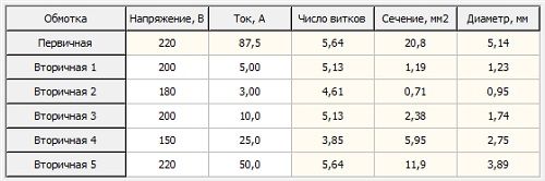
As a result of calculating the transformer online, the output parameters are obtained in the form of power, current strength in amperes, the number of turns and the diameter of the wire in the primary and secondary winding.
There are those that allow you to quickly perform transformer calculations. However, they do not give a full guarantee against errors in the calculations. To avoid such troubles, a program is used online calculator. The results obtained make it possible to design transformers for various powers and voltages. With the help of a calculator, not only transformer calculations are carried out. There is an opportunity to study its structure and basic functions. The requested data is inserted into the table and all that remains is to press the desired button.
Thanks to the online calculator, you do not need to carry out any independent calculations. The results obtained allow you to rewind the transformer with your own hands. Most of the necessary calculations are carried out in accordance with the dimensions of the core. The calculator simplifies and speeds up all calculations as much as possible. You can get the necessary explanations from the instructions and follow their instructions clearly in the future.
The design of transformer magnetic circuits is represented by three main options - armored, rod and. Other modifications are much less common. The calculation of each type requires initial data in the form of frequency, input and output voltage, output current and dimensions of each magnetic core.
Viktor Khripchenko Oktyabrsky, Belgorod region
Being engaged in calculations of a powerful power supply, I ran into a problem - I needed a current transformer that would accurately measure the current. There is not much literature on this topic. And on the Internet, only requests - where to find such a calculation. I read the article; knowing that errors may be present, I dealt with this topic in detail. Errors, of course, were present: there is no terminating resistor Rc (see Fig. 2) to match the output of the secondary winding of the transformer (it was not calculated) in terms of current. The secondary circuit of the current transformer is calculated as usual for a voltage transformer (set the right voltage on the secondary winding and made the calculation).
A bit of theory
So, first of all, a little theory. The current transformer operates as a current source with a given primary current, representing the current of the protected section of the circuit. The magnitude of this current is practically independent of the load of the secondary circuit of the current transformer, since its resistance to the load, reduced to the number of turns of the primary winding, is negligible compared to the resistance of the electrical circuit elements. This circumstance makes the operation of a current transformer different from that of power transformers and voltage transformers.
On fig. 1 shows the marking of the ends of the primary and secondary windings of the current transformer, wound on the magnetic circuit in the same direction (I1 - primary winding current, I2 - secondary winding current). The current of the secondary winding I2, neglecting the small magnetizing current, is always directed in such a way as to demagnetize the magnetic circuit.
The arrows show the direction of the currents. Therefore, if we take the upper end of the primary winding as the beginning, then the beginning of the secondary winding is also its upper end. accepted rule marking corresponds to the same direction of currents, given the sign. And the most important rule: the condition of equality of magnetic fluxes.
The algebraic sum of the products I 1 x W 1 - I 2 x W 2 \u003d 0 (neglecting a small magnetizing current), where W 1 is the number of turns of the primary winding of the current transformer, W 2 is the number of turns of the secondary winding of the current transformer.
Example. Let you, having given a current of the primary winding of 16 A, made a calculation and in the primary winding of 5 turns - calculated. You are given a current of the secondary winding, for example, 0.1 A and according to the above formula I 1 x W 1 \u003d I 2 x W 2 we calculate the number of turns of the secondary winding of the transformer.
W 2 = I 1 x W 1 / I 2
Further, after calculating the L2 -inductance of the secondary winding, its resistance XL1, we calculate U2 and then Rc. But this is a little later. That is, you see that by setting the current in the secondary winding of the transformer I2, you only then calculate the number of turns. The current of the secondary winding of the current transformer I2 can be set to any - from here Rc will be calculated. And yet -I2 should be more than the loads that you will connect
The current transformer should only operate on a current-matched load (we are talking about Rc).
If the user needs a current transformer for use in protection circuits, then such subtleties as the direction of windings, the accuracy of the resistive load Rc can be neglected, but this will no longer be a current transformer, but a current sensor with a large error. And this error can be eliminated only by creating a load on the device (I mean the power source where the user is going to put protection using a current transformer), and set the threshold for its current operation by the protection circuit. If the user requires a current measurement circuit, then just these subtleties must be observed.
On fig. 2 (points - the beginning of the windings) shows the resistor Rc, which is an integral part of the current transformer for matching the currents of the primary and secondary windings. That is, Rc sets the current in the secondary winding. It is not necessary to use a resistor as Rc, you can put an ammeter, a relay, but the obligatory condition must be observed - internal resistance load must be equal to the calculated Rc.
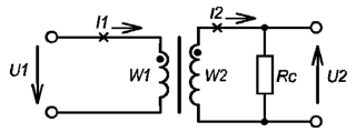
If the load is not matched in current, it will be an overvoltage generator. I explain why. As mentioned earlier, the current of the secondary winding of the transformer is directed in the opposite direction from the direction of the current of the primary winding. And the secondary winding of the transformer works as a demagnetizer. If the load in the secondary winding of the transformer is not matched in current or is absent, the primary winding will work as a magnetizing one. The induction increases sharply, causing a strong heating of the magnetic wire due to increased losses in the steel. The EMF induced in the winding will be determined by the rate of flux changes over time, which has highest value during the passage of a trapezoidal (due to saturation of the magnetic circuit) flow through zero values. The inductance of the windings decreases sharply, which causes even more heating of the transformer and, ultimately, its failure.
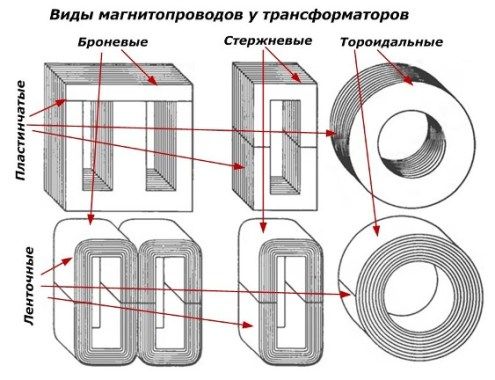
The types of magnetic cores are shown in fig. 3 .
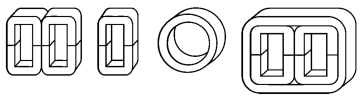
A twisted or tape magnetic circuit is the same concept, as well as the expression ring or toroidal magnetic circuit: both are found in the literature.
It can be a ferrite core or W-shaped transformer iron, or tape cores. Ferrite cores are usually used at higher frequencies - 400 Hz and higher due to the fact that they work in weak and medium magnetic fields(W = 0.3 T maximum). And since ferrites, as a rule, have a high value of magnetic permeability µ and a narrow hysteresis loop, they quickly enter the saturation region. The output voltage, at f = 50 Hz, on the secondary winding is a few volts or less. As a rule, ferrite cores are marked with their magnetic properties (example M2000 means the magnetic permeability of the core µ, equal to 2000 units).
There is no such marking on tape magnetic cores or from Ш-shaped plates, and therefore it is necessary to determine their magnetic properties experimentally, and they work in medium and strong magnetic fields (depending on the grade of electrical steel used - 1.5 ... .2 T and more ) and are applied at frequencies of 50 Hz.. .400 Hz. Ring or toroidal twisted (tape) magnetic cores also operate at a frequency of 5 kHz (and from permalloy even up to 25 kHz). When calculating S - the cross-sectional area of a tape toroidal magnetic circuit, it is recommended to multiply the result by the coefficient k \u003d 0.7 ... 0.75 for greater accuracy. This is explained design feature strip magnetic circuits.
What is a tape split magnetic circuit (Fig. 3)? Steel tape, 0.08 mm thick or thicker, is wound on a mandrel, and then annealed in air at a temperature of 400 ... .500 ° C to improve their magnetic properties. Then these forms are cut, the edges are polished, and the magnetic circuit is assembled. Ring (continuous) twisted magnetic circuits made of thin tape materials (permalloy 0.01...0.05 mm thick) are covered with electrically insulating material during winding and then annealed in vacuum at 1000...1100 °C.
To determine the magnetic properties of such magnetic circuits, it is necessary to wind 20 ... 30 turns of wire (the more turns, the more accurate the value of the magnetic permeability of the core) on the core of the magnetic circuit and measure the L-inductance of this winding (μH). Calculate S - cross-sectional area of the transformer core (mm2), lm - average length of the magnetic field line(mm). And according to the formula, calculate jll - magnetic permeability of the core:
(1) µ = (800 x L x lm) / (N2 x S) - for strip and E-shaped core.
(2) µ = 2500*L(D + d) / W2 x C(D - d) - for a toroidal core.
When calculating a transformer for higher currents, a large diameter wire is used in the primary winding, and here you will need a twisted core magnetic circuit (P-shaped), a twisted ring core or a ferrite toroid.
If someone held an industrial-made current transformer for high currents in his hands, he saw that there was no primary winding wound on the magnetic circuit, but there was a wide aluminum bus passing through the magnetic circuit.
I recalled this later that the current transformer can be calculated either by setting the W - magnetic induction in the core, while the primary winding will consist of several turns and you will have to suffer winding these turns on the transformer core. Or it is necessary to calculate the magnetic induction W of the field created by a current-carrying conductor in the core.
And now let's proceed to the calculation of the current transformer, applying the laws .
You are given the primary current of the current transformer, that is, the current that you will control in the circuit.
Let it be I1 = 20 A, the frequency at which the current transformer will operate, f = 50 Hz.
Let's take a tape ring core OJ125/40-10 or (40x25x10 mm), shown schematically in fig. four.
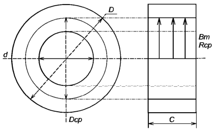
Dimensions: D = 40 mm, d = 25 mm, C = 10 mm.
Then there are two calculations with detailed explanations of exactly how the current transformer is calculated, but too many formulas make it difficult to lay out the calculations on the site page. For this reason full version an article on how to calculate a current transformer has been converted to PDF and can be downloaded using
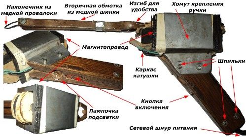
Included home master it is necessary to have a soldering iron, sometimes even several different capacities and designs. The industry produces many different models, they are not difficult to acquire. The photo shows a working sample of the release of the 80s.
However, many craftsmen are interested in homemade designs. One of them at 80 watts is shown in the photographs below.
This soldering iron was able to solder copper wires 2.5 squares outside in the cold and change transistors and other components electronic circuits on the printed circuit boards in laboratory conditions.
Principle of operation
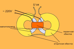
Soldering iron "Moment" works from electrical network~ 220 volts, representing an ordinary transformer, in which the secondary winding is shorted with a copper jumper. When energized for a few seconds, current flows through it short circuit, heating the copper tip of the soldering iron to temperatures that melt the solder.
The primary winding is connected by a cord with a plug to the socket, and a switch with a mechanical spring self-return is used to supply voltage. When the button is pressed and held, a heating current flows through the soldering iron tip. As soon as you release the button, the heating stops immediately.
In some models, for the convenience of working in low light conditions, a 4-volt tap is made from the primary winding according to the principle of an autotransformer, which is led to a cartridge with a light bulb from a flashlight. The directional light of the collected source illuminates the place of soldering.
Transformer design
Before starting the assembly of the soldering iron, you should decide on its power. Usually 60 watts is enough for simple electrical and amateur radio work. In order to constantly solder transistors and microcircuits, it is desirable to reduce the power, and to process massive parts, it is increased.
For manufacturing, it will be necessary to use a power transformer of the appropriate power, preferably from old devices from the times of the USSR, when all the electrical steel of the magnetic cores was produced according to the requirements of GOST. Unfortunately, in modern designs there are facts of making transformer iron from low-quality and even ordinary steel, especially in cheap Chinese devices.
Types of magnetic circuit
Iron must be selected according to the power of the transmitted energy. For this, it is permissible to use not one, but several identical transformers. The shape of the magnetic core can be rectangular, round or W-shaped.
Iron of any shape can be used, but it is more convenient to choose armored plate because it has a higher power transfer efficiency and allows you to make composite structures by simply adding plates.
When choosing iron, you should pay attention to the absence of an air gap, which is used only in chokes to create magnetic resistance.
Simplified Calculation Method
How to choose iron according to the required power of the transformer
Let us immediately make a reservation that the proposed method was developed empirically and allows you to assemble a transformer from randomly selected parts at home, which works normally, but under certain circumstances can produce slightly different parameters from the calculated ones. This is easy to fix with fine-tuning, which in most cases is not required.
The relationship between the volume of iron and the power of the primary winding of the transformer is expressed through the cross section of the magnetic circuit and is shown in the figure.
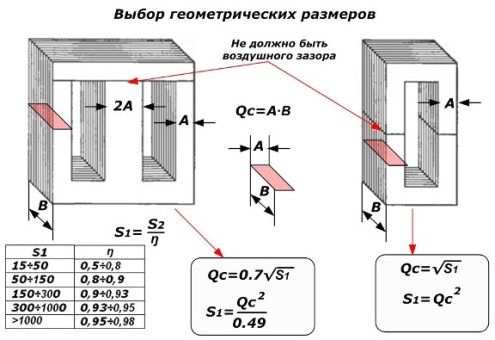
The power of the primary winding S1 is greater than the secondary winding S2 by the efficiency value ŋ.
The sectional area of a rectangle Qc is calculated using a well-known formula through its sides, which are easy to measure with a simple ruler or caliper. For an armored transformer, the volume of iron is required by 30% less than for a rod one. This is clearly seen from the above empirical formulas, where Qc is expressed in square centimeters, and S1 is in watts.
For each type of transformer, according to its own formula, the power of the primary winding is calculated through Qc, and then its value in the secondary circuit, which will heat up the soldering iron tip, is estimated through efficiency.
For example, if a W-shaped magnetic core is selected for 60 watts of power, then its cross section is Qc=0.7∙√60=5.42cm 2 .
How to choose the wire diameter for the transformer windings
The material for the wire should be copper, which is covered with a layer of varnish for insulation. When winding turns on coils, the varnish eliminates the appearance of interturn short circuits. The thickness of the wire is selected according to the maximum current.
For the primary winding, we know the voltage of 220 volts and decided on the primary power of the transformer, choosing the cross section for the magnetic circuit. By dividing the watts of this power by the volts of the primary voltage, we get the winding current in amperes.
For example, for a transformer with a power of 60 watts, the current in the primary winding will be less than 300 milliamps: 60 [watts] / 220 [volts] \u003d 0.272727.. [amps].
In the same way, the secondary winding current is calculated from its voltage and power values. In our case, this is not necessary: a winding of two turns, the voltage will be small, and the current will be large. Therefore, the cross section of the current lead is selected with a huge margin from a copper bar, which will minimize losses from electrical resistance secondary winding.
Having determined the current, for example, 300 mA, it is possible to calculate the wire diameter using the empirical formula: wire d [mm]=0.8∙√I [A]; or 0.8∙√0.3=0.8 0.547722557505=0.4382 mm.
Such precision, of course, is not needed. The calculated diameter will allow the transformer to work very long and reliably without overheating at maximum load. And we make a soldering iron that periodically turns on for just a couple of seconds. Then it turns off and cools down.
Practice has shown that a diameter of 0.14 ÷ 0.16 mm is quite suitable for these purposes.
How to determine the number of winding turns
The voltage at the terminals of the transformer depends on the number of turns and the characteristics of the magnetic circuit. Usually we do not know the grade of electrical steel and its properties. For our purposes, this parameter is simply averaged, and the entire calculation of the number of turns is simplified to the form: ώ = 45 / Qc, where ώ is the number of turns per 1 volt of voltage on any transformer winding.
For example, for the considered transformer of 60 watts: ώ=45/Qc=45/5.42=8.3026 turns per volt.
Since we connect the primary winding to 220 volts, the number of turns for it will be ω1=220∙8.3026=1827 turns.
The secondary circuit uses 2 turns. They will give out a voltage of only about a quarter of a volt.
For uniform distribution of wire turns inside the magnetic circuit, it is necessary to make a frame from electrical cardboard, getinaks or fiberglass. The technology of work is shown in the figure, and the dimensions are chosen taking into account the design of the magnetic circuit. The windings isolated by the frame are placed in a coil, around which the plates of the magnetic circuit are assembled.
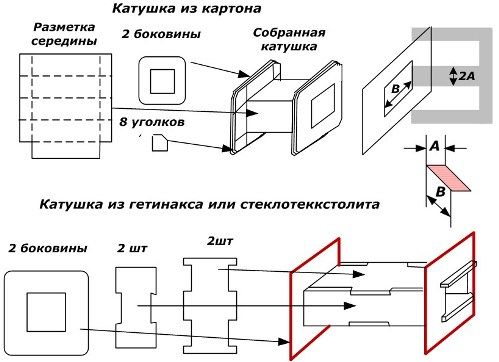
It is often possible to use a factory frame, but if you need to add plates to increase power, you will have to increase the dimensions. Cardboard parts can be sewn with ordinary threads or glued together. The case made of fiberglass with precise fitting of parts can be assembled even without glue.
In the manufacture of the coil, one should try to allocate as much space as possible for the placement of the windings, and when winding the turns, place them close and evenly. When placing the wire in bulk, there may simply not be enough space and all the work will have to be redone.
In the soldering iron shown in the photograph, the secondary winding is made of a copper bar with a rectangular cross section. Its dimensions are 8 by 2 mm. You can use other profiles as well. For example, it will be convenient to bend a round wire to fit inside the magnetic circuit. With a flat shank, I had to tinker hard, use a vise, hammer, templates and a file to evenly bend strictly according to the configuration of the coil frame.
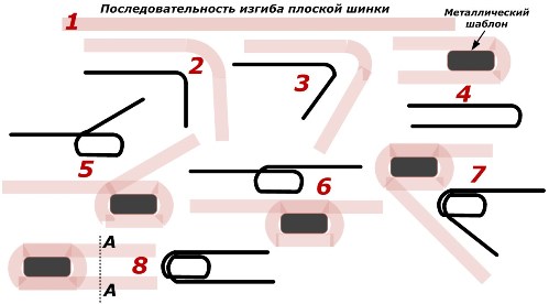
In the figure, position 1 shows a flat shank. After making the frame, you need to determine its length, taking into account the distance that it will take for turns and the distance to the copper wire tip.
In position 2, it is smoothly bent approximately in the middle in a vice with small hammer blows in compliance with the orientation plane. When crossing a bend through a right angle, it is necessary to use a mild steel template with a shape strictly corresponding to the dimensions of the coil frame in which the winding will be placed.
The template greatly facilitates locksmith work on giving the winding the desired shape. First, one half of the shank is wrapped around it, which is shown in positions 4, 5 and 6, and then the other (see 7 and 8).
To facilitate understanding of the process, next to the images of the shank in positions, black lines with slight distortion show a sequence of bends.
On position 8 conditionally shown section A-A. Near it, it will be necessary to bend the shank by 90 degrees for the convenience of work, as shown in the photo.
If there are bends that prevent the free placement of the power winding inside the coil frame, they can be cut with a file. The coils of metal should not touch each other and the body. To do this, they are separated by a layer of not thick insulation.
Holes are drilled at the ends of the secondary winding and threads are cut for screwing M4 screws. They serve to fasten a copper tip made of 2.5 or 1.5 square wire. Since the voltage on the secondary winding is very small, the quality of the electrical contacts of the tip must be monitored, kept clean, cleaned of oxides and reliably squeezed with nuts and washers.
Making the primary winding of the soldering iron
After the power winding of the soldering iron is ready and insulated, it will become clear how much free space is left in the coil for thin wire. With a shortage of space, the turns are placed tightly together.
The winding wire consists of a copper core and one or more layers of varnish and is marked PEV-1 (single-layer varnish coating), PEV-2 (two layers), PETV-2 (more heat-resistant than PEV-2), PEVTLK-2 (heat-resistant special).
When measuring the diameter of the wire with a micrometer, the resulting reading should be reduced by the thickness of the insulation. But this general recommendation for our soldering iron is not critical.
Given the work under heating conditions, it is better to refuse the PEV-1 brand, by the way, it is also not recommended to wind it in bulk.
Usually, the wire is wound on a coil on homemade machines.
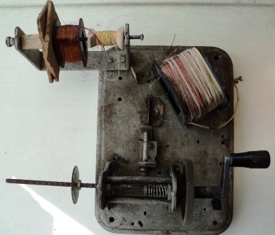
When the power winding is put on the frame, it will be necessary to make the turns manually and write down their number on paper at a certain interval, for example, one hundred or two hundred.
Before starting work, solder to the beginning of the winding stranded wire in strong insulation, preferably MGTF brand. It will withstand repeated bending, heating, mechanical stress for a long time. The ends are connected by soldering, insulated. The flux is selected only rosin, acid is not allowed.
The flexible core is fixed in the coil from pulling out and is brought out through the hole in the side wall. After winding is completed, the second end of the winding is also soldered to the MGTF wire, which is brought out.
Since 220 volts will be applied to the wire, it should be well insulated from the housing and the secondary winding.
Design development
After winding the coil, iron is tightly installed on it, securing it with wedges from falling out. Before the final assembly of the case, you can check the operation of the soldering iron by applying voltage to the primary winding to warm up the tip and evaluate the current-voltage characteristic.
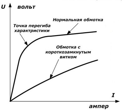
If the assembled structure is well soldered, then this can not be done. But, for information: it is desirable to guess the operating point of the CVC at the point of inflection of the curve, when the iron has reached its saturation. This is done by changing the number of turns.
The method of determination is based on the supply AC voltage from a regulated source to the transformer winding through an ammeter and a voltmeter. Several measurements are taken and a graph is built based on them, showing the turning point (iron saturation). Then a decision is made to change the number of turns.
Handle, housing, switch
Any button with a self-resetting, designed for currents up to 0.5 A, is suitable as a switch. The photo shows a microswitch from an old tape recorder.
The handle of the soldering iron is made of two halves of solid wood, in which cavities are cut to accommodate wires, a button and a light bulb. In fact, the backlight is not required, for it you need to make a separate tap or a resistive-capacitive divider.
The halves of the handles are tightened with studs and nuts. A metal clamp is mounted on them, which must be isolated from the iron of the magnetic circuit.
The open homemade case design shown in the photo provides better cooling, but requires attention and safety from the worker.
Bravy Alexey Semenovich
We advise you to read
 Psychological characteristics of children in adolescence
 Transferring a child to another school - the procedure and necessary documents Whether to transfer a child to another school
, diagnosis, treatment Treatment of urogenital chlamydia") Chlamydia urogenital - description, causes, symptoms (signs), diagnosis, treatment Treatment of urogenital chlamydia
Chlamydia urogenital - description, causes, symptoms (signs), diagnosis, treatment Treatment of urogenital chlamydia The benefits and significance of hydroamino acid threonine for the human body L threonine what

