§ 105. DEVICE OF A DC GENERATOR
Fixed part in machines direct current is inductive, i.e., creates a magnetic field, and the rotating part is inductive (armature).
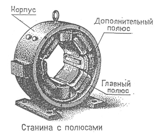
The stationary part of the machine (Fig. 134, a) consists of main poles 1, additional poles 2 and frame 3. The main pole (Fig. 134, b) is an electromagnet that creates a magnetic flux. It consists of a core 4, an excitation winding 7 and a pole piece 8. The poles are attached to the frame 6 with a bolt 5. The pole core is cast from steel and has an oval cross section. On the core of the pole is marked the excitation coil, wound from insulated copper wire. Coils of all poles are connected in series, forming an excitation winding. The current flowing through the excitation winding creates a magnetic flux. The pole piece holds the field winding on the pole and ensures even distribution magnetic field below the pole. The pole piece is shaped in such a way that the air gap between the poles and the armature is the same along the entire length of the pole arc. Additional poles also have a core and a winding.
Additional poles are installed at midpoints between the main poles, and their number can be either equal to the number of main poles, or half as much. Additional poles are installed in machines of high power, and they serve to eliminate sparks under the brushes. In low power machines, there are usually no additional poles.
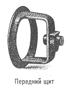
The frame is cast from steel and is the skeleton of the machine. The main and additional poles are attached to the frame, as well as side shields with bearings holding the machine shaft on the end sides. With the help of the frame, the machine is attached to the foundation.
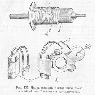
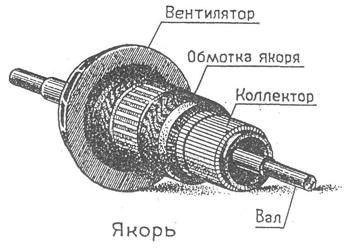
The rotating part of the machine (anchor) (Fig. 135, a) consists of a core 1, a winding 2 and a collector 3. The armature core is a cylinder assembled from sheets of electrical steel. The sheets are insulated from each other with varnish or paper to reduce eddy current losses. Steel sheets are stamped on machines according to a template; they have grooves in which the conductors of the armature winding are laid. Air channels are made in the armature body to cool the winding and the armature core.
The armature winding is made of copper insulated wire or from copper rods of rectangular cross section. It consists of sections made on special templates and laid in the grooves of the anchor core. The single-turn section consists of two active wires connected to each other.
Sections can have not one, but many turns. Such sections are called multi-turn. The winding is carefully isolated from the core and fixed in the grooves with wooden wedges. The frontal connections are reinforced with steel bandages. All sections of the winding placed on the armature are interconnected in series, forming a closed circuit. The wires connecting two sections following one after the other according to the winding scheme are attached to the collector plates.
The collector is a cylinder consisting of individual plates. Collector plates are made of hard-drawn copper and insulated between themselves and from the body with micanite gaskets. For mounting on the sleeve, the collector plates are shaped like a dovetail, which is clamped between the protrusion on the sleeve and the washer, having a shape corresponding to the shape of the plate. The washer is bolted to the bushing.
The collector is the most complex in terms of design and the most critical part of the machine in operation. The surface of the commutator must be strictly cylindrical to avoid beating and sparking of the brushes.
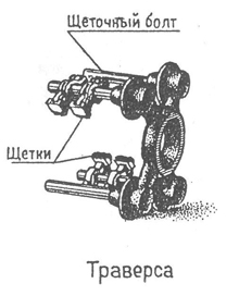
To connect the armature winding to the external circuit, fixed brushes are placed on the collector, which can be graphite, carbon-graphite or bronze-graphite. In high voltage machines, graphite brushes are used, which have a large contact resistance between the brush and the collector, in low voltage machines, bronze-graphite brushes are used. Brushes are placed in special brush holders (Fig. 135, b). The brush 4, placed in the holder of the brush holder, is pressed against the collector by the spring 5. Each brush holder can have several brushes connected in parallel.
The brush holders are mounted on brush bolts-pins, which, in turn, are fixed on the traverse. For fastening on the brush finger, the brush holder has a hole.
The brush fingers are isolated from the traverse by insulating washers and bushings. The number of brush holders is usually equal to the number of poles.
The traverse is mounted on a bearing shield in machines of small and medium power or attached to the frame in machines of large powers. The traverse can be rotated and thereby change the position of the brushes relative to the poles.
Usually the traverse is installed in a position in which the location of the brushes in space coincides with the location of the midpoints of the main poles.
DC electrical machines
DC electrical machines according to their purpose are divided into electrical generators(or just generators) that transform mechanical energy into electrical at constant voltage (generators are sources of electrical energy), and electric motors(electric motors) that convert electrical energy direct current into mechanical energy. This mechanical energy is used to rotate any actuator (machine, winch, tram wheels, electric trains, etc.).
In addition, there are some special types of machines, such as machines designed to convert DC electricity into electricity. alternating current or vice versa; micromachines used in systems automatic regulation, in measuring and calculating devices as sensors (for example, speed sensors), etc.
The electrical industry produces machines ...
direct current of various power and voltage. Conventionally, they can be divided into the following power groups:
1) micromachines, the power of which is measured from fractions of a watt to 500 W;
2) low power machines - 0.5 ÷ 10 kW;
3) machines of medium power - from 10 to several hundred kilowatts;
4) machines of high power - over several hundred kilowatts.
The voltage of DC machines varies from 6-12 V for those used in vehicles to 30 kV for those used in radio installations.
DC machines with a power of up to 200 kW for a voltage of 110-440 V with a rotation speed of 550-2870 rpm are of great use. Micromachines have speeds from a few revolutions to 30,000 rpm.
In industry, transport and agriculture most widely used electric motors. Generators are used to power communication devices, radio installations, etc. In recent years, more economical and easy-to-use static semiconductor converters have been increasingly used as DC sources.
The operation of the generator is based on the use of the law of electromagnetic induction, according to which in a conductor moving in a magnetic field and crossing the magnetic flux, an EMF is induced.
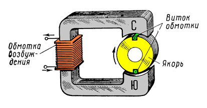
One of the main parts of a DC machine is the magnetic circuit, through which the magnetic flux closes. The magnetic circuit of a DC machine consists of a fixed part - stator 1 and rotating part rotor 4. The stator is a steel case to which other parts of the machine are attached, including magnetic poles. 2. An excitation winding is mounted on the magnetic poles 3, powered by direct current and creating main magnetic flux F 0 .
The rotor of the machine is assembled from stamped steel sheets with grooves around the circumference and with holes for the shaft and ventilation. . In grooves 5 rotor is laid working winding DC machines, i.e., a winding in which an EMF is induced by the main magnetic flux. This winding is called armature winding(therefore, the rotor of a DC machine is commonly called an armature).
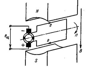
The poles of a permanent magnet create a magnetic flux. Let us imagine that the armature winding consists of one turn, the ends of which are attached to various half-rings isolated from each other. These semicircles form collector, which rotates with the coil of the armature winding. At the same time, fixed brushes slide along the collector.
When a coil rotates in a magnetic field, an e is induced in it. d. s
where AT - magnetic induction; l- conductor length; v- its line speed.
When the plane of the coil coincides with the plane of the center line of the poles (the coil is located vertically), the conductors cross the maximum magnetic flux and the maximum EMF value is induced in them. When the coil occupies a horizontal position, the EMF in the conductors is zero.
The direction of the EMF in the conductor is determined by the right hand rule. When, during the rotation of the coil, the conductor passes under the other pole, the direction of the EMF in it changes to the opposite. But since the collector rotates along with the coil, and the brushes are stationary, a conductor located under the north pole is always connected to the upper brush, the EMF of which is directed away from the brush. As a result, the polarity of the brushes remains unchanged, and therefore remains unchanged in the direction of the EMF on the brushes - e u.
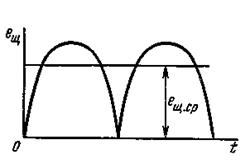
Although the EMF of the simplest DC generator is constant in direction, it changes in value, taking two times the maximum and two times zero values in one turn of the coil. EMF with such a large ripple is unsuitable for most DC receivers and in the strict sense of the word it cannot be called constant.
To reduce ripples, the armature winding of a DC generator is made of a large number of turns (coils), and the collector is made of a large number of collector plates isolated from each other. As a result of this, the EMF ripple of the armature winding decreases. With an increase in the number of turns and collector plates, it is possible to obtain an almost constant EMF of the armature winding.
familiarize yourself with the device operating principle, the main modes of operation of the DC generator with independent excitation;
acquire practical skills in starting, operating and stopping a DC generator;
experimentally confirm the theoretical information about the characteristics of the DC generator.
Basic theoretical provisions
DC electric machines can operate both in generator mode and in engine mode, i.e. have the reversibility property.
DC generator - it's electric a machine designed to convert mechanical energy into direct current electrical energy.
DC motor- an electrical machine designed to convert direct current electrical energy into mechanical energy.
General form electrical machine DC is shown in fig. one.
The device of the DC electric machine
Like any other electrical machine, a DC machine consists of a fixed part - stator and rotating part - rotor 1, performing the function anchors, since EMF is induced in its windings.
In the stator of the machine there is an excitation winding that creates the necessary magnetic flux F. The stator consists of a cylindrical frame 2 (cast steel, steel pipe or welded sheet steel), to which the main 3 and additional 4 poles with excitation windings are attached. From the ends of the stator, bearing shields 5 are closed. Bearings are pressed into them and the brush traverse with brushes 6 is strengthened.
The armature consists of a cylindrical package (made of lacquered sheets of electrical steel to reduce eddy currents). A winding is placed in the grooves of the armature core, connected to collector 7; all this is fixed on the armature shaft.
Operating principle
The simplest electrical machine can be represented as a coil rotating in a magnetic field (Fig. 2, a,b). The ends of the coil are brought out to two collector plates. Fixed brushes are pressed against the collector plates, to which an external circuit is connected.
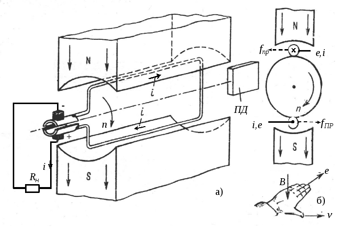
The principle of operation of an electric machine is based on the phenomenon of electromagnetic induction. Consider the principle of operation of an electric machine in generator mode. Let the coil be driven by an external drive motor (PD). The coil crosses the magnetic field, and according to the law of electromagnetic induction, a variable EMF is induced in it , the direction of which is determined by the rule of the right hand. If the external circuit is closed, then a current will flow through it, directed from the lower brush to the consumer and from it to the upper brush. The bottom brush turns out to be the positive terminal of the generator, and the top brush turns out to be the negative. When the coil is rotated by 180 0, the conductors from the zone of one pole pass into the zone of the other pole and the direction of the EMF in them will change to the opposite. At the same time, the upper collector plate comes into contact with the lower brush, and the lower plate with the upper brush, the direction of the current in the external circuit does not change. Thus, the collector plates not only provide a connection between the rotating coil and the external circuit, but also act as a switching device, i.e. are the simplest mechanical rectifier.
To reduce ripples in the DC generator, instead of one coil, several evenly spaced windings are placed around the armature circumference, which form the armature winding, and are connected to a collector consisting of a larger number of segments to change the polarity of the EMF. Therefore, the EMF in the circuit between the brush terminals pulsates not so much, i.e. turns out to be almost constant.
For this constant EMF, the expression is valid
E=With 1 Фn,
where With 1 - coefficient depending on the structural elements of the armature and the number of poles of the electric machine; F- magnetic flux; n- frequency of rotation of the armature.
When the machine is operating in the generator mode, a current flows through a closed external circuit and a coil of the armature winding i = I i, the direction of which coincides with the direction of the EMF (see Fig. 2, b). According to Ampère's law, the interaction of current i and magnetic field AT creates strength f, which is perpendicular to AT and i. Force direction f is determined by the rule of the left hand: the force acts on the upper conductor to the left, on the lower one to the right. This pair of forces creates a torque M vr, directed in this case counterclockwise and equal to
M=With 2 FI I.
This torque counteracts the drive torque, i.e. is the braking moment.
armature current I I causes in the armature winding with resistance R I voltage drop R I I I , so under load the voltage U at the conclusions of the brushes it turns out less than EMF, namely
U = E – R I I I.
Generators are electrical machines that convert mechanical energy into electrical energy. The principle of operation of an electric generator is based on the use of the phenomenon of electromagnetic induction, which is as follows. If the conductor is moved in the magnetic field of a permanent magnet so that it crosses the magnetic flux, then a electromotive force(emf), called emf induction (Induction from the Latin word inductio - guidance, motivation), or induced emf. An electromotive force also occurs when the conductor remains stationary and the magnet moves. The phenomenon of the occurrence of induced emf. in a conductor is called electromagnetic induction. If the conductor in which the emf is induced is included in a closed electrical circuit, then under the action of emf. A current will flow through the circuit, called induced current.
It has been experimentally established that the magnitude of the induced emf that occurs in the conductor when it moves in a magnetic field increases with an increase in the magnetic field induction, the length of the conductor and the speed of its movement. Induced emf occurs only when the conductor crosses the magnetic field. When the conductor moves along the magnetic lines of force emf it is not induced. The direction of the induced emf. and current is easiest to determine by the rule of the right hand (Fig. 1): if the palm of the right hand is held so that the magnetic field lines enter it, the bent thumb would show the direction of movement of the conductor, then the remaining extended fingers will indicate the direction of action of the induced e. d.s. and the direction of the current in the conductor. Magnetic field lines are directed from the north pole of the magnet to the south.
Rice. 1. Determining the direction of the induced emf. right hand rule
Having a general idea of electromagnetic induction, let's consider the principle of operation of the simplest generator (Fig. 2). The conductor in the form of a frame made of copper wire is fixed on an axis and placed in a magnetic field. The ends of the frame are attached to two halves (half rings) of one ring isolated from one another. Contact plates (brushes) slide on this ring. Such a ring, consisting of isolated half rings, is called a collector, and each half ring is called a collector plate. The brushes on the collector must be arranged in such a way that, when the frame rotates, they simultaneously pass from one half ring to another just at those moments when the emf induced in each side of the frame is zero, i.e. when the frame passes its horizontal position.
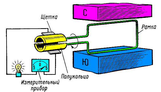
Rice. 2. The simplest DC generator
With the help of a collector, the variable emf induced in the loop is rectified, and a current that is constant in direction is created in the external circuit.
By connecting to the contact plates an external circuit with an electrical measuring device that fixes the magnitude of the induced current, we will make sure that the considered device is indeed a DC generator.
At any time t e.m.f. E (Fig. 3), arising in the working side L of the frame, is opposite in the direction of the emf arising in the working side B. The direction of the emf. on each side of the frame is easy to determine using the right hand rule. The emf induced by the entire frame is equal to the sum of the emf that occurs in each of its working side. The emf value in the frame changes continuously. At the time when the frame approaches its vertical position, the number of lines of force crossed by the conductors in 1 s will be the largest and the maximum emf is induced in the frame. When the frame passes the horizontal position, its working sides slide along the lines of force without crossing them, and the emf. is not induced. During the movement of side B of the frame to the south pole of the magnet (Fig. 3, a, b), the current in it is directed towards us. This current passes through the half ring, brush 2, measuring device to the brush / to side A of the frame. In this side of the loop, the current is induced away from us. His the greatest value emf in the frame reaches when its sides are located directly under the poles (Fig. 3, b).
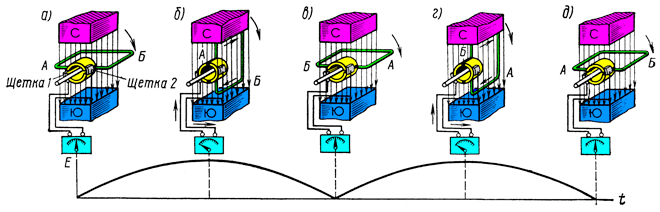
Rice. 3. The scheme of the DC generator
With further rotation of the frame, the emf decreases in it and after a quarter of a turn becomes equal to zero (Fig. 3, c). At this time, the brushes move from one half ring to another. Thus, during the first half turn of the frame, each half-ring of the commutator was in contact with only one brush. The current passed through the external circuit in one direction from brush 2 to brush 1. We will continue to rotate the frame. The electromotive force in the frame begins to increase again, since its working sides will cross the magnetic lines of force. However, the direction of the emf reverses because the conductors traverse the magnetic flux in the opposite direction. The current induced in side A of the frame is now directed towards us. But due to the fact that the frame rotates together with the collector, the semi-ring connected to side A of the frame now comes into contact not with brush 1, but with brush 2 (Fig. 3, d) and a current passes through the external circuit in the same direction as in the time of the first half of the revolution. Therefore, the collector rectifies the current, i.e., ensures the passage of the induced current in the external circuit in one direction. By the end of the last quarter of a turn (Fig. 3, e), the frame returns to its original position (see Fig. 3, a), after which the entire process of changing the current in the circuit is repeated.
Thus, a constant emf acts between brushes 2 and 1, and the current through the external circuit always flows in one direction - from brush 2 to brush 1. Although this current remains constant in direction, it varies in magnitude, t e. pulsates. Such a current is practically difficult to use.
Consider how you can get a current with a small ripple, that is, a current whose value changes little during the operation of the generator. Imagine a generator consisting of two coils located perpendicular to one another (Fig. 4). The beginning and end of each turn is connected to a collector, which now consists of four collector plates.
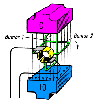
Fig.4. DC generator with two turns
When these turns rotate in a magnetic field, an emf arises in them. However, the emfs induced in each turn reach their zero and maximum values not simultaneously, but later one another for a time corresponding to the rotation of the turns by a quarter of a full turn, i.e. by 90 °. In the position shown in Fig. 4, in coil 1, the maximum emf arises, equal to Emach. In the coil 2 e. d.s. is not induced, since its working sides slide along the magnetic lines of force without crossing them. The emf values of the turns are shown in Fig.5. As the coils turn, the emf of coil 1 decreases. When the turns turn 1/8 of a turn, the emf. turn 1 will become equal to Emin. At this moment, the brushes move to the second pair of collector plates connected to coil 2. Coil 2 has already turned 1/8 of a turn, crosses the magnetic lines of force, and an emf equal to the same value Emach is induced in it. With a further turn of the turns, the emf turn 2 increases to the maximum value Emakh. Thus, the brushes are always connected to the coils, in which the emf is induced with a value from Emin to Emax.
Fig.5. Pulsation curves of the electromotive force of a two-turn generator
The current in the external circuit of the generator arises as a result of the action of the total emf. Therefore, it flows continuously and only in one direction. The current, as before, will be pulsating, but the ripple is much less than with one turn, since the emf. generator does not drop to zero.
By increasing the number of conductors (turns) of the generator and, accordingly, the number of collector plates, it is possible to make the current ripples very small, i.e., the current will become almost constant in magnitude. For example, already with 20 collector plates, the emf fluctuations generator will not exceed 1% of the average. In the external circuit, we obtain a current that is practically constant in magnitude.
At the same time, it is easy to see that the generator shown in Fig. 4 also has a very significant drawback. At any given moment in time, the external circuit is connected by means of brushes to only one turn of the generator. The second round at the same time is not used at all. The electromotive force induced in one turn is very small, which means that the generator power will also be small.
For continuous use of all turns, they are connected to each other in series. For the same purpose, the number of collector plates is reduced to the number of winding turns. The end of one and the beginning of the next turn of the winding are attached to each collector plate. The turns in this case are series-connected sources electric current and form the armature winding of the generator. Now the electromotive force of the generator is equal to the sum of the emfs induced in the turns connected between the brushes. In addition to serial, there are other schemes for connecting winding turns. The number of turns is taken large enough to obtain the required emf value. generator. Therefore, the collectors of diesel electric machines are obtained with a large number of plates.
Thus, due to the large number of turns of the winding, it is possible not only to smooth out voltage and current ripples, but also to increase the value of the emf induced by the generator.
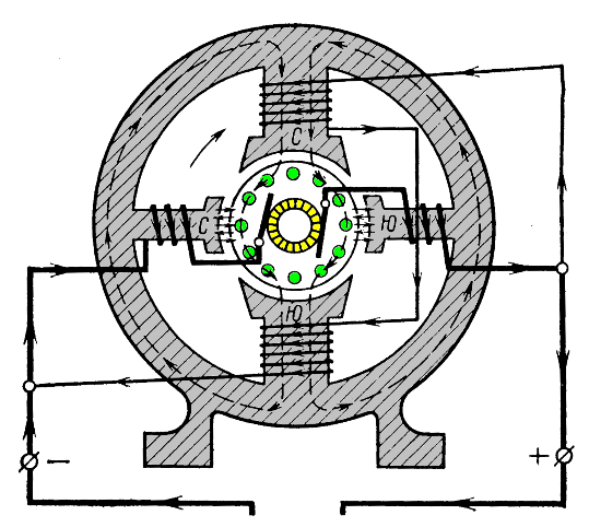
Above, an electric generator was considered, consisting of permanent magnets and one or more turns in which current occurs. For practical purposes, such generators are unsuitable, since it is impossible to obtain large power from them. This is explained by the fact that the magnetic flux created by the permanent magnet is very small. In addition, the space between the poles creates a significant resistance to the magnetic flux. The magnetic flux is further weakened. Therefore, in powerful generators, which include diesel ones, electromagnets are used that create a strong magnetic excitation flux (Fig. 6). To reduce the magnetic resistance of the magnetic circuit of the generator, the turns of the winding are placed on a steel cylinder, which fills almost the entire space between the poles.
This cylinder with a winding and a collector placed on it is called the generator armature.
Rice. 6. Scheme of a generator with an electromagnetic excitation system and a massive steel anchor
The excitation winding of the generator is located on the cores of the main poles. When current passes through it, a magnetic field is created, called the field of the main poles. With an open external circuit of the generator, the magnetic field lines are located in the poles and armature symmetrically to the vertical axis (Fig. 7, a). To understand the features of the operation of an electric machine, we introduce the concepts of geometric and physical neutrals.
A geometric neutral is a line drawn through the center of the armature perpendicular to the axis of the opposite poles (horizontal line 01-01). The physical neutral is a conditional line that separates the zones of influence of the north and south poles on the armature winding and runs perpendicular to the direction of the magnetic flux of the electric machine.
In the winding conductor, which, when the armature rotates, passes through the physical neutral, emf. is not induced, since such a conductor slides along the magnetic field lines without crossing them. In the absence of current in the armature (see Fig. 7, a) the physical neutral n-n coincides with the geometric neutral.
Fig.7. anchor reaction.
a is the magnetic flux of the main poles; b - magnetic flux created by the armature winding; c is the total magnetic flux of the loaded generator
When the external circuit of the electric machine is closed, the current will also flow through the armature winding. The entire armature in this case will be a powerful electromagnet, consisting of a steel core and a winding through which current flows. Therefore, in addition to the pole flux, there is a second magnetic flux in the loaded generator, called the armature flux (Fig. 7, b). The magnetic flux of the armature is directed perpendicular to the flux of the main poles. Both magnetic fluxes are superimposed on each other and form a total, or resulting, field, shown in Fig. 7, c. The direction of the magnetic field of the generator as a result of the action of the armature field is shifted in the direction of armature rotation. The physical neutral is also shifted in the same direction, which in this case occupies the position n1-n1.
The influence of the magnetic field of the armature on the field of the poles is called the armature reaction. Armature reaction adversely affects the operation of the generator. Brushes M-M of the electrical machine must always be installed in the direction of the physical neutral. Therefore, it is necessary to shift the generator brushes with respect to the geometric neutral by a certain angle P (Fig. 7, c), since otherwise strong sparking occurs between the brushes and the collector. Sparking causes burning of the surface of the commutator and brushes and disables them. The greater the armature current, the stronger the armature reaction, the greater the angle it is necessary to shift the brushes. With frequent changes in the load of a diesel generator, the position of its brushes would have to be changed almost continuously.
The armature reaction not only shifts the magnetic field of the main poles, but also partially weakens it, which leads to a decrease in the e induced by the generator. d.s.
To weaken the armature reaction in generators, additional poles are installed between the main poles, and sometimes, for the same purpose, a compensation winding is laid in the pole pieces of the main poles. Additional poles create an additional magnetic field, which is directed towards the armature field in the brush installation areas, as a result of which its effect is neutralized (Fig. 8).
Rice. 8. Generator circuit with additional poles
However, the positive effect of additional poles on the operation of the generator is not limited to this. After passing through the neutral of the generator, the direction of the current in each turn of the winding (see Fig. 7) very quickly changes to the opposite. In neutral, the coil is short-circuited by the brushes. Such a turn is called commuting (Commutation from the Latin word commutatio - change, change). In the switching turns (sections) of the armature winding, due to a very rapid change in the direction of the current, a rather large emf arises. self-induction and mutual induction, which is called reactive emf. This emf in switching sections is enhanced by the action of the magnetic flux of the armature, which they cross. The action of reactive emf. leads to strong sparking of the brushes. Additional poles are calculated so that their magnetic flux is somewhat greater than the magnetic flux of the armature. Due to this, an additional emf is induced in the switching sections. New emf has a direction opposite to the reactive emf, and extinguishes it, preventing intense sparking.
The magnetic field of the armature changes with a change in the load (current) of the generator, therefore, to neutralize it, it is necessary to change the field of the compensation devices. The winding of the additional poles is connected in series with the armature winding, and the entire armature current passes through it. With an increase in the generator current, the magnetic flux of the armature increases, but at the same time, the magnetic flux of the additional poles compensating for it also increases.
The compensation winding makes it possible to further improve the distribution of the magnetic flux in the electric machine. So, from Fig. 7 it is easy to see that as a result of the action of the armature reaction, the magnetic flux of the main poles becomes uneven - on one side of the pole it increases, and on the other it weakens. This leads to an uneven load of the armature winding, some of the turns will be overloaded, and the operating conditions of the brushes deteriorate.
By means of a compensating winding located on the main poles, the distortion of the magnetic flux directly below the main poles is eliminated. However, the simultaneous use of additional poles and compensation winding greatly complicates the design of electrical machines. If it is possible to carry out a satisfactory operation of an electric machine through the use of additional poles, then they try not to use a compensation winding. Compensation windings found practical use only in powerful electric machines.
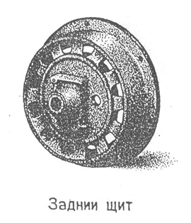
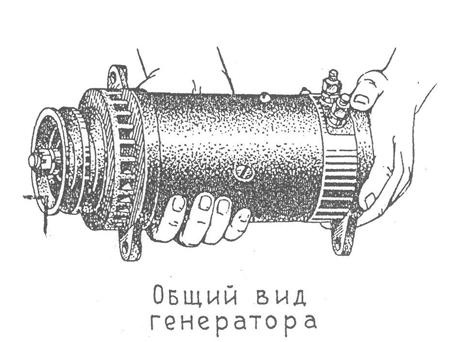
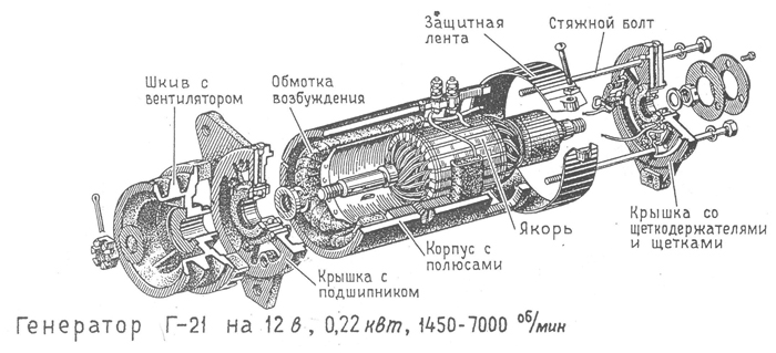
The following figures show the G-21 generator for 12 V, 0.22 kW, 1450 -7000 rpm.
We advise you to read
, diagnosis, treatment Treatment of urogenital chlamydia") Chlamydia urogenital - description, causes, symptoms (signs), diagnosis, treatment Treatment of urogenital chlamydia
Chlamydia urogenital - description, causes, symptoms (signs), diagnosis, treatment Treatment of urogenital chlamydia The benefits and significance of hydroamino acid threonine for the human body L threonine what
 To wait or not to wait for a guy from the army For what reason can they be commissioned from the army
 Baked apples with cottage cheese Baked apples with cottage cheese

