In everyday life, it is often necessary to turn off the light after a certain time. There is a need for pantries and simple outbuildings. In turn, and in other cases, when it is necessary to limit the operation of an electronic device in time, a simple digital timer will be used in place, which allows you to turn the load on or off after a certain period.
Simple digital timer for turning on and off the light, which you can assemble with your own hands, is built on only one integrated counter K561IE16. As you know, for the operation of any counter, an external clock generator is needed. In our case, its role is played by a simple blinking LED.
Description of the operation of a simple digital timer
As soon as the timer is powered on, C1 is charged through the resistance R2, as a result of which a log.1 appears briefly at pin 11, turning all counter outputs to zero. The transistor connected to the meter output will open and the relay will operate, connecting the load with its contacts.
From a blinking LED with a frequency of about 1.4 Hz, pulses are sent to the clock input (leg 10) of the counter DD1. With each fall of the input pulse, the counter is incremented. After 256 pulses (in time it will take approximately 256 / 1.4 Hz = 183 seconds or ~ 3 minutes), a log.1 occurs at pin 12. In this regard, the transistor will close, de-energizing the load. Plus, log.1 from output 12 is fed to the clock input DD1 through the VD1 diode, thereby stopping the timer.
The frequency of the timer can be selected by connecting the connection point of the resistor R3 and diode VD1 to different outputs of DD1. By slightly tweaking this circuit, it is possible to build a timer that performs the opposite function of work. The change affects the transistor VT1. It must be changed to a transistor of a different structure.
Now, when log.1 appears at the output of the counter, the transistor will open and turn on the load. Instead of an electric relay in this version, it is possible to turn on a simple sound emitter with an internal generator, for example, HCM1612X. It is necessary to connect the electric emitter observing the polarity.
Light on and off timer details
Diodes VD1-VD2 series KD103, KD522, KD103, KD521, KD102. Transistors KT814A can be changed to KT973 or KT814. arbitrary from the KT604, KT815 series. In addition to the K561IE16 counter, it is possible to use its foreign analogue CD4020B. You can also use the CD4060 chip, which already has a clock generator, so the LED and resistance R1 can be removed. LED - flashing type ARL5013URCВ, L816BRSCВ, L56DGD,
The timer is quite economical in terms of energy consumption. The current that the timer consumes, not taking into account the current of the relay, is about 11 mA.
Nowadays, photo sensors are most often used to control lighting on the street and the territory adjacent to the house. ().
Photo sensors turn on lighting depending on the amount of natural light. Somehow it happened that everyone forgot the most popular technical solution of the recent past - turning the lighting on and off with the help of daily time switch.
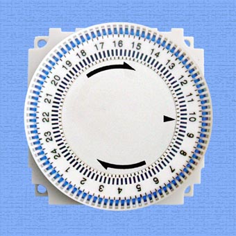
Even before the advent of photoresistors and other photocells, various methods were actively used to automate lighting. automatic devices with clockwork. These devices turned the lights on and off at predetermined times of the day. For example, there were widespread relay 2РВ (single-program) and 2RVM (two-program).
The principle of operation of these relays was based on the rotation of a program disk with holes into which special pins were screwed according to a given program. The disc was rotated by a clock mechanism. The clockwork spring was wound up under the action of an electromagnet. When the disk rotated, the pins pressed the microswitches and at the same time turned on and off the lighting.
 This lighting control method has its advantages and disadvantages. The advantages are mainly due to the fact that the operation of the lighting installation is not affected by any accidental illumination. A relay is a relatively simple device and it can be placed absolutely anywhere, including indoors, while it must be located in a place where natural light is controlled. In addition, there is no need to determine the required illumination threshold.
The main disadvantage of using a daily time switch is that the time of sunrise and sunset is constantly changing, which requires regular adjustment of the mechanism to new values of the time of sunrise and sunset, which is very inconvenient. If this is not done, then through certain time such relays gave large errors when turned on, for example, they turned on the lamps, when there was no need for this at all due to sufficient good level natural light.
With the rapid development of electronics and microprocessor technology, more and more smart devices appear that implement reminiscent of old proven technical solutions at a higher quality level.
Since in some cases it is incredibly difficult to limit a conventional light sensor from accidental illumination, a device can come to the rescue in which there is no need for an external light sensor - digital astronomical timer.
According to its principle of operation, such a device is similar to the clockwork of the past. But unlike their predecessors, modern devices of this type are able to automatically calculate the time of sunrise and sunset and make switching in the output circuits (turning on and off light sources) only when it is really necessary.
Digital astronomical timers are produced by a large number of manufacturers and in their own way. technical specifications they are all very similar.
An example of such a device is astronomical timer Rex 2000 from Legrand.
In order for the Rex 2000 astronomical timer to correctly determine the time of sunrise and sunset in the timer's memory, at its initial setting, you must enter the date, time and local coordinates (longitude and latitude) of the area where it will be operated. At the same time, the Rex astronomical timer is suitable for use anywhere in the world.

Legrand Rex2000 astronomical timer
Switching the timer () occurs without the use of a photosensitive element. In order to save energy at night, the timer can be programmed to turn off. The switching time is easily determined by the segmented display.
It is possible to correct the time of switching on and off within +/- 60 minutes from the values of the times of sunrise and sunset calculated by the astronomical timer. In addition, the control input "S" of the timer allows you to turn on the timer regardless of the current program. According to the manufacturer, the accuracy of the timer is +/- 1 s / day.
The timer automatically switches to "winter" / "summer" time. Has a sealable lid. FACE programming interface. Different models of timers can be powered by 230 V or 24 V. Operating temperature -20 ... +55 ° C. Degree of protection - IP20.
There is a model of an astronomical timer that can control two channels at once. The timer has 1 or 2 changeover contacts for 16 A for a purely resistive load or 4 A for an inductive load (at cos phi = 0.6). If you need to connect more powerful lamps through the timer, then in this case the lamps must be connected via. In this case, the astronomical timer will no longer control the line directly, but the coil of the electromagnetic starter.

Rex2000 Astronomical Timer Wiring Diagram
Some manufacturers have a function in the astronomical timer to automatically determine the time of sunrise and sunset according to the entered city name and the current date. In addition, the timer can have a built-in counter of the time worked by the timer and the number of load switching on, the ability to enter a password in order to exclude someone else's interference in the operation of the device.
Most automatic timers are available for mounting on a DIN rail (standard 35 mm wide metal rail) and have a simple circuit connections.
The astronomical timer, while retaining all the advantages of a device with a clock mechanism (the main advantage is that there is no need to install a light sensor), controls light sources depending on natural light (though determined by calculation).
Nov 21 2016
Timers are actually used in many cases.
For example, some exhaust fans already contain a device for counting the time. The point here is that after turning off the blade does not stop, but works for some more time.
It is assumed that over the past period the bathroom will be cleared of steam. Let's see how to connect and set up a lighting control timer.
Varieties of lighting control timers
To begin with, there are three types of timers according to their design:
- Overhead mounted directly on the wall.
There are no special features, but it should be remembered that electrical wiring is pulled over a combustible base only in fireproof insulation.
In addition, it is necessary to carry out in most cases a protective gasket. For example, in the form of a fireproof box, or plaster on the wall. You can read more about these recommendations in PUE 6, where there is a whole table listing all the options.
We explain that we are talking about open wiring for the simple reason that it is most often combined with overhead switches.
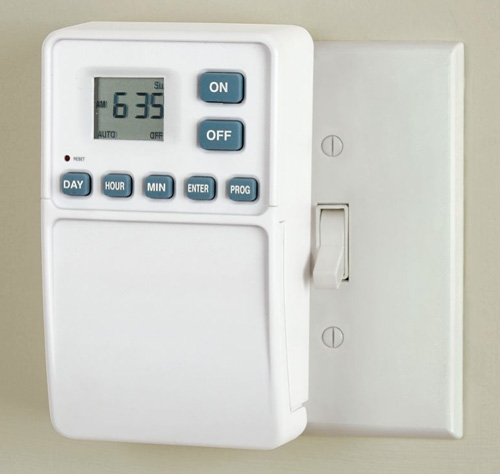
- On sale you can find timers mounted in a conventional socket.
In this case, carefully look at the diameter, because in this regard the dimensions differ
And in some cases it will be quite difficult to install. Ceteris paribus, you need to choose a timer that will fit into an existing socket, for example, in place of a switch.
- Today, a lot of timers are sold that are mounted on DIN rails.
These are special guides, which, as a rule, are found in all modern shields.
Therefore, it will not be difficult to carry out installation.
In this case, you can power the entire apartment from the timer, if there is any reasonable explanation for this.
We ask the readers to see how, using a timer, you can replace the pass-through and other complex types of switches that are usually used in combination to control one source from different places!
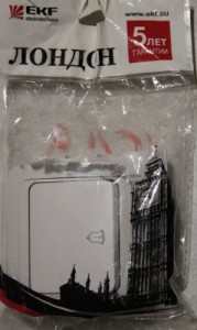
Remote timer from F&F
So here it is! F&F AS-222T timers are available for sale, which can be remotely controlled by buttons. Where can I get so many buttons? - And to be beautiful. Just a minute!
Look at the photo: what is it? Call button. It differs from the London single switch only by the presence of a return spring inside and a small bell icon.
If necessary, this marking can be removed by rearranging the button from another product of the same company and series (this is done without difficulty).
In this case, we can arrange such buttons - got some air? - as much as you like!
In the presence of a long corridor, we will put "bells" wherever it pleases. With one condition: the contacts must converge to the place where the timer is installed.
However, it is not prohibited to use junction boxes, so there are ample opportunities for switching.
We made a screenshot from the official manual on English language taken directly from the F&F website. Firstly, this is the same model for the TH-35 DIN-line, which we talked about above.
The characteristics, in particular, say that this block takes the place of two modules at once. This allows you to estimate in advance the capabilities of your switchboard.
We can see that the turn-on delay is less than one second. Much or little, you will have to check on your own skin, but it is allowed to vary the delay from half a minute to 600 seconds. This is more than enough in most cases.
 It is written that half a minute before extinction, the intensity of light falls. This visually reminds the owner that the shutdown is coming soon…
Brilliant? In our opinion, it would be nice to find another solution.
For example, when pressed again, the light could go out.
This is not important, but it better allows you to implement your plan.
Let's say you can't put such a "through" switch in the bedroom, because waiting for it to fade is simply unrealistic.
What does the bedroom have to do with it, you ask? In fact, it will not be difficult to supply power to the chandelier in parallel.
In this case, it would be possible to put a conventional switch at the input, which would open and close the circuit. How is that, you ask? And what happens if the timer and the switch simultaneously apply a phase? It's okay if it's the same phase.
In this case, the potential difference between the devices will be zero. Another thing is that they usually don’t do this, and even there seem to be no prohibitions (although not a fact).
Timer with calculation of solar cycles
 The Apel company produces timers, where the moments of sunrise and sunset in a given area are calculated at a given latitude. You can make adjustments if necessary.
Depending on the type of devices, you can make settings for:
- The need to include the days of the week.
- Adjustments to calculated data.
- The current time and date.
Adjustments are required due to geographical conditions. These are the unevenness of the terrain, and the content of various components in the air.
Apel timers provide an opportunity to make corrections general type and quarterly. This turns out to be sufficient in most cases.
In addition to this, some Apel timers have two relays. One of them works according to the principle described above, and the second can be configured more flexibly. This is mainly to save light. For example, in the early morning hours on weekends, it is allowed not to turn on the load.
It is clear that you don’t want to be energized when replacing light bulbs, so Apel timers are switched to test mode for the duration of technical work. The manual says that both relays turn on.
We are inclined to assume that this is a typo, or some kind of subtle move in order to remove tension from the cartridges. Because, judging by the timer connection diagram, both zero and phase are supplied to it. In this case, after a short circuit, voltage is applied to the load, and in this case it is impossible to change the light bulbs due to the danger of this event.
There is a fuse inside the Apel timer, and if the system as a whole does not work, then it is logical to start checking from here. But not every performance has it.
For example, it is not possible to ring a fuse in timers for a DIN ruler. In all other cases, its outputs are between terminals 2 and 3.
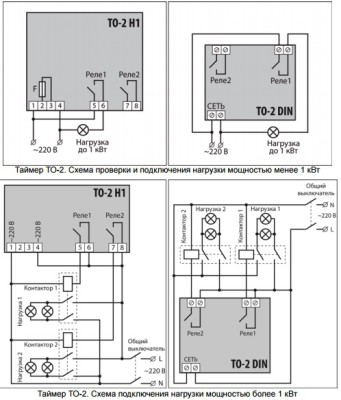 From the diagram taken in the official manual, it can be seen that the load is connected in parallel with the timer itself. That is, it can be considered a simple device in this sense.
However, the lighting circuit is interrupted by the timer's internal contactors. In this case, the total power consumption should not exceed 1 kW.
If more is required, the bottom figure is used, where external contactors are used.
This is necessary to prevent sparking inside the timer and, as a result, its failure.
It is clear that the external contactors must be sized for the applied power.
Otherwise, they will already fail. Finally, a contactor is a device for safe switching of loads.
All those interested can refer to GOST R 50030.4.1. In particular, it says that a contactor is a device that ensures that the load is connected not manually, but in another way.
For example, a closing force can be generated by an electromagnet. Thus, it is necessary to connect the lighting control timer through external contactors in the presence of a powerful load. In this case, the total consumption can be increased up to 5 kW.
 In addition to electromagnetic, there are many other types of contactors. Obviously, in our case, the device must be controlled by electricity.
I would like to point out that the application energy saving lamps can increase the return by 10 times (by an order of magnitude) luminous flux. Which, of course, is a more profitable mode.
To set the timer in certain conditions, be guided by information on the security of the case by IP, as well as standards (for example, for a bathroom, this is GOST 505071.11).
Please note that the DIN version is not protected at all. This is because the body of the switchboard should already protect its filling from extraneous influences.
To set the Apel TO-2 lighting control timer, only three buttons are used: switching functions and arrows for increasing and decreasing the parameter. The display is liquid crystal, which allows you to place all the information on the screen in a very convenient way.
Timer Specifications
Frame
You probably already understood that one of the most important characteristics is the execution of the case. It will depend on this whether it will be possible to set the timer to switchboard or not, whether to hang it on the wall or mount it in a socket. In many cases, this is decisive.
For example, for private apartment the wall version looks, to put it mildly, not very beautiful
On the other hand, not everyone has a switchboard at home. In this case, the option remains in the socket. In addition, the type of housing design also determines the degree of protection according to IP, which is decisive when choosing a mounting location.
Load current
The parameter shows how much the timer can carry. It is ideal for those establishments where everything goes according to schedule.
Suppose, at the right time, the main lighting is turned off by the timer, and auxiliary lighting remains, requiring less energy.
 The barracks immediately comes to mind, however, if you think about it, then any cafe works on schedule. And in the event that it is required to serve the company outside the plan, a separate changeover switch can be provided.
In any case, automation will play a positive role, and some time before the end of working hours, it can turn off part of the load, signaling this.
This is very convenient for banks (subdued light from a distance will make it clear that the office is closed), and for offices. The load current must not be exceeded to prevent equipment failure.
Working method
This designation is not marked separately. You have seen that, along with fully automatic timers, there are remote-controlled models.
In the case of TO2 from Apel, the entire board changes. The filling consists mainly of a microcontroller, which is not possible to reprogram at home.
Operating temperature range
This parameter will immediately allow you to separate the options for the premises from the outdoor version. If the manufacturer's requirements are not followed, the equipment will fail. The temperature spread of outdoor timers is usually large, and the range of indoor units falls within the range of these products.
Delay range
In controlled timers, the concept of a time delay range usually appears. This is the interval after which the device will turn off automatically.
Similar mechanisms are usually used for bathroom exhaust fans, as we mentioned at the beginning of the review.
Connecting a timer
The connection of the lighting control timer is not always carried out through contactors, as one might think. This moment is closely related to the maximum load current. Most timers for powerful appliances are simply not suitable.
In turn, a high-quality contactor is not included in the housing by default in order to reduce the cost of the timer: it is clear that not every house has 5 kW of light bulbs.
Timer setting
 It is very important how the lighting control timer is set. You have seen that there can be quite a few algorithms.
Surely in nature there are also externally programmable timers, where the algorithm is loaded through the interface of some port (COM, USB).
Obviously, the second option is ideal for large companies where there may be a need to change the lighting conditions in a large area.
It is clear that running and clicking buttons is not very convenient, but the main thing is not even that - there is a possibility of making a mistake. And what will be the consequences depends on the specifics of the venue.
We advise you to read
 Psychological characteristics of children in adolescence
 Transferring a child to another school - the procedure and necessary documents Whether to transfer a child to another school
, diagnosis, treatment Treatment of urogenital chlamydia") Chlamydia urogenital - description, causes, symptoms (signs), diagnosis, treatment Treatment of urogenital chlamydia
Chlamydia urogenital - description, causes, symptoms (signs), diagnosis, treatment Treatment of urogenital chlamydia The benefits and significance of hydroamino acid threonine for the human body L threonine what

