Overhead power line towers
Overhead lines with a voltage of 0.4-35 kV
Overhead lines with voltage up to 1 kV are called low voltage lines (LV), 1 kV or more - high voltage(VN).
Low-voltage lines are the simplest structures in the form of single poles buried directly into the ground, with metal pins and insulators attached to them, to which wires are attached.
As supports, wooden, reinforced concrete and, less commonly, metal supports are used. The latter, as a rule, are used at critical intersections (electrified railways, highways, etc.). Wooden supports can be composite on wooden or reinforced concrete attachments or from solid logs of the appropriate length and diameter. Three wires are suspended on 6-35 kV lines, and on 0.4 kV lines, supports allow joint suspension of up to eight wires of brand A (Ap) with a cross section of 16-50 mm2.
HV lines 3-10 kV do not fundamentally differ from LV lines, however, due to the large distances between the phases and between the wires and the ground, the dimensions of the elements - poles, pins, insulators - are increased.
Reinforced concrete pylons for power transmission lines are designed and operated in areas with design air temperatures down to -55°C. The main element of such supports are centrifuged reinforced concrete racks. In addition to centrifuged racks, the structure of the reinforced concrete support of power transmission lines can include anchor plates, crossbars, anchors for guy wires, a lower concrete cover (thrust bearing) and metal structures in the form of traverses, extensions, cable racks, head restraints, clamps, braces, internal connections, attachment points. Fastening of metal structures to the support post is carried out using clamps or through bolts. Reinforced concrete supports are fixed in the ground by installing them in a cylindrical pit, followed by filling the sinuses with a sand and gravel mixture. To ensure the necessary strength of embedding in soft soils, crossbars are fixed on the underground part of the overhead line supports with the help of half-clamps. The main disadvantage of reinforced concrete supports is their low strength and weight characteristics, and as a result, high transportation costs due to the large dimensions and weight of the products. Dignity - high corrosion resistance to aggressive environments.
Classification reinforced concrete supports VL
By appointment
intermediate supports are installed on straight sections of the overhead line route, are intended only for supporting wires and cables and are not designed for loads directed along power lines. As a rule, the total number of intermediate supports is 80 - 90% of all power transmission line supports.
Anchor supports are used on straight sections of the overhead line route at places of transition through engineering structures or natural barriers to limit the anchor span, as well as in places where the number, grades and cross sections of power line wires change. Anchor support perceives the load from the difference in tension of wires and cables, directed along the power line. The design of anchor reinforced concrete supports of overhead lines is characterized by increased strength. This is ensured, among other things, by the use of reinforced concrete pillars of increased strength in the support.
Angle supports designed for operation in places where the direction of the overhead line route changes, they perceive the resulting load from the tension of wires and cables of adjacent intersupport spans. At small angles of rotation (15 - 30 °), where the loads are small, angular intermediate supports are used. At angles of rotation of more than 30 °, angled anchor supports are used, which have a stronger structure and anchor fastening of wires.
end supports are a kind of anchor and are installed at the end and beginning of the power line, designed for the load from the one-sided tension of all wires and cables.
Special supports used for special tasks: transpositional- to change the order of the wires on the supports; transitional- to cross the power line through engineering structures or natural barriers; branch- for the device of branches from the main power line; antiwind- to enhance the mechanical strength of the power line section; cross- when crossing overhead power lines in two directions.
By design
Portal reinforced concrete supports of overhead lines with braces
Portal free-standing supports with internal connections
Single, double, triple and multi-column free-standing poles
One-, two-, three- and multi-stay guyed poles
By number of chains
single chain
double chain
Multi-chain
|
SUPPORTS OF AIR LINES. |
|
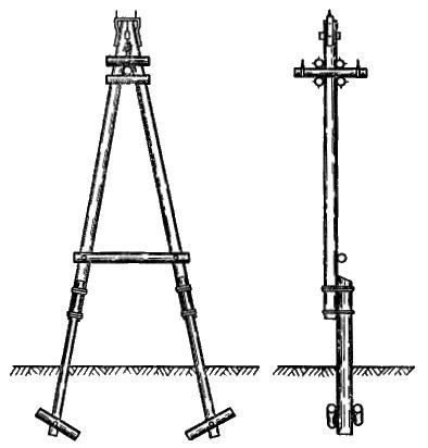
Overhead line supports depending on the purpose and installation location on the track, they can be intermediate, anchor, corner, end and special. intermediate supports(see figure below) are used to support wires on straight sections of lines. On the intermediate supports, the wires are fixed with pin insulators. The spans between supports for lines with voltage up to 1000V are 35 - 45 meters, and for lines up to 10kV - 60 meters. Overhead line supports: a and 6 - intermediate, c - angular with a brace, g - angled with wire guy Anchor supports(see figure below) are also installed on straight sections of the route and on those crossed with various structures. They have a rigid and durable design, since under normal conditions they perceive the forces from the tension difference along the wires directed along the overhead line, and in the event of a wire break, they must withstand the tension of all remaining wires in the anchor span. Wires on anchor supports are fixed tightly to suspension or pin insulators. Anchor supports for overhead lines with a voltage of 10 kV are placed at a distance of about 250 meters.
Overhead line anchor voltage 6 - 10kV end supports, which are a type of anchor, are installed at the beginning and end of the line. The end supports must withstand the permanent one-sided tension of the wires, and the corner supports (see the top figure c and d) - in places where the direction of the overhead line route changes. Special ones include transitional supports placed at the intersections of various structures or obstacles by power lines (for example, rivers, railways and so on.). These supports differ from others of this line in height or design. The supports are made of wood, metal, reinforced concrete, and are also made composite, matching the wooden support post with a wooden or reinforced concrete attachment. For overhead lines with voltage up to 10 kV For a long time, mainly wooden supports were used, which was due to the ease of processing wood and its cheapness compared to steel and reinforced concrete. The supports were made of pine, less often of larch, spruce or fir. The diameter in the upper cut of pine logs for supports and main parts must be at least 15 cm for lines with voltage up to 1000V and 16 cm for lines with voltage 1 - 10 kV. The main disadvantage of wooden untreated supports is their fragility. So, the service life of pine poles is on average 4-5 years, and poles made of spruce or fir 3-4 years. At present, reinforced concrete supports, due to their durability and in order to save the country's forest resources, are wide application in the construction of new air networks. By design wooden supports divide: on single; A-shaped of two racks diverging towards the base; three-legged of three stances converging to the top; U-shaped of two racks and a connecting horizontal traverse at the top (transverse beam); AP-shaped from two A-shaped supports and a connecting horizontal traverse. Composite supports are also used, consisting of a rack and a prefix (stepson). In these cases, the interface between the rack and the attachment must be at least 1300 mm (see figure below).
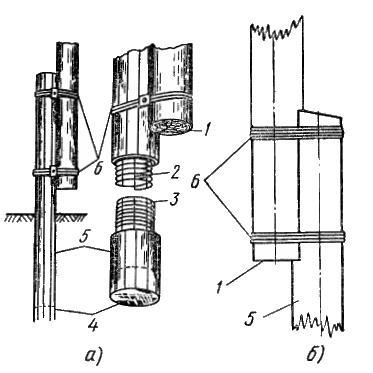
Pairing a wooden support rack with an attachment: a - reinforced concrete, b - wooden; I and 4 - the lower part of the support and attachment, 2 and 3 - longitudinal and transverse reinforcement, 5 - prefix, 6 -. wire bandage Racks are connected to attachments with steel wire bandages. For intermediate supports, bandages are made of ten turns of wire with a diameter of 4 mm, for anchor, corner and end supports - of eight turns of wire with a diameter of 5 mm. Wire bandages are fixed with bolts, placing rectangular washers made of strip steel under the head of the bolts and under the nuts. Steel supports made of pipes or profile steel. Reinforced concrete supports are produced by factories in the form of hollow round-section racks with an outer diameter decreasing in steps and rectangular also with a decreasing section towards the top of the support. The factories also produce reinforced concrete prefixes of a round or rectangular profile. When using reinforced concrete attachments and wooden racks impregnated with an antiseptic, the service life of the supports is significantly extended. Overhead power line towers irrespective of their type, they can be performed with braces or braces (see the top figure wig). On all supports of overhead lines at a height of 2.5 - 3.0 meters from the ground, their serial number and year of installation are indicated. |
|
WIRES |
|
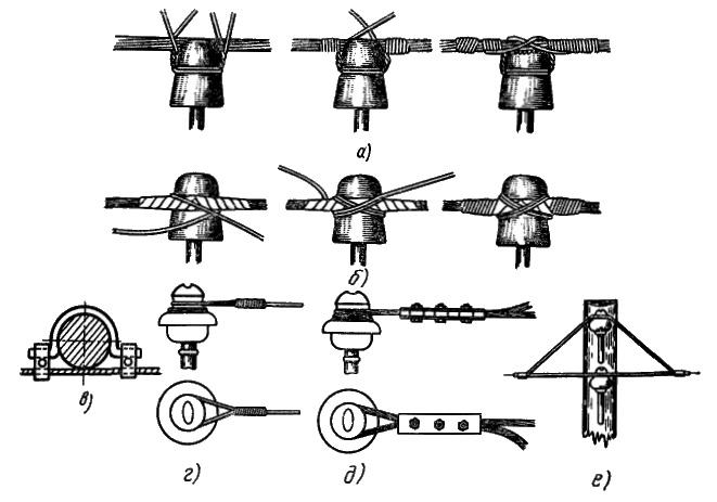
Overhead line wires must have sufficient mechanical strength. By design, the wires can be single-wire or multi-wire. Single-wire wires consist of one copper or steel wire and are used exclusively for lines with voltage up to 1000V. Stranded wires made of copper, aluminum and its alloys, steel and bimetal, consist of several twisted wires. These wires are widely used due to their greater mechanical strength and flexibility compared to single wires of the same cross section. Copper wires due to the scarcity and high cost of copper for overhead lines do not use. Aluminum stranded wires of brand A are widely used on overhead lines. Steel wires are galvanized for protection from atmospheric influences. Single-core steel wires have the PSO brand, multi-wire - PS or PMS, if copper steel is used as the wire material. Steel-aluminum wires of grades AS and ASU (reinforced) consist of several twisted steel wires, on top of which aluminum wires are located, and have significantly greater mechanical strength compared to aluminum ones. Non-isolated aluminum wires make the following sections: 6, 10, 16, 25, 35, 50, 70, 95, 120 mm 2. The cross-sections of the wires of overhead lines are determined by calculation depending on the transmitted power, permissible voltage drops, mechanical strength, span length, but they must not be less than those indicated in the following table. Minimum cross-sections of wires of overhead power lines To branch from a line with a voltage of up to 1000V to the inputs to the building, use insulated wires APR or AVT having weather-resistant insulation and a supporting steel cable. Both on the support and on the building, the ABT wires are attached to a separate hook with an insulator using a cable. On intermediate supports, the wires are attached to the pin insulators with clamps or knitting wire of the same material as the wire, which should not have bends at the attachment point. Wire fastening methods depend on their location on the insulator - on the head (head knitting) or on the neck (side knitting). The main ways of attaching wires are shown in the following figure.
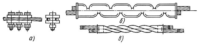
Fastening wires on pin insulators: a - head viscous, b - lateral viscous, c - with clamps, d - plug, d - loop, e - double suspension On anchor, corner and end supports overhead line wires up to 1000V they are fixed by twisting the wires with a so-called plug (see figure, d), and above 1000V - with a loop (see figure, e). On anchor and corner supports, at the points of transition through railways, driveways, tram tracks and at intersections with various lines of force and communication lines use a double suspension of wires (see figure, e). Wire connection produced by die clamps (see the figure below, a), a crimped oval connector (see the figure below, b), an oval connector twisted with a special device (in the figure, c), as well as welding using thermite cartridges and a special apparatus. Single-wire steel wires can be overlap welded using small transformers. In the span between the supports there should not be more than one connection, and in the spans of intersections of the overhead line with various structures, the connection of wires is not allowed. On the supports, the connections are made so that they are not subjected to mechanical stress.
Wire connection: a - ram clamp, 6 - crimped oval connector, c - twisted oval connector |
|
INSULATORS |
|
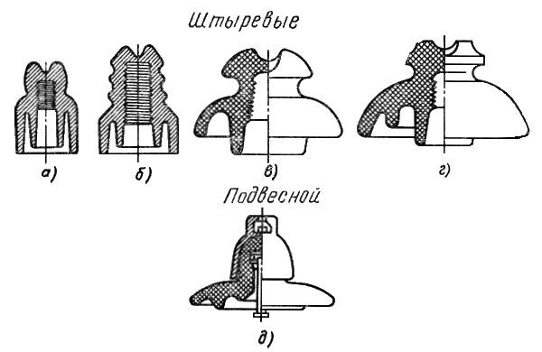
When attaching the wires of overhead lines to the supports, apply insulators and hooks, and when attached to the traverse - insulators and pins. For overhead lines with voltage up to 1000V, pin porcelain insulators TF and ShN are used (figure below, a), for SHO branches (figure below, b) and glass TS.
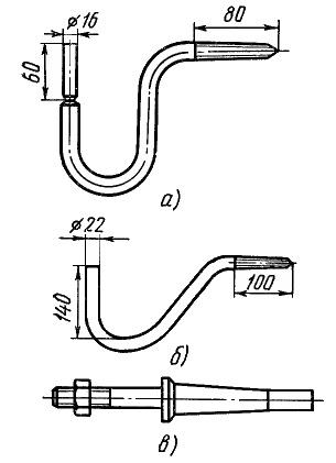
Insulators used for overhead lines, grades: a - TF and ShN, b - SHO, c - ShF-bA and ShF-10A, d - ShF-10B, e - P Hooks and pins for attaching insulators are shown in the figure below. For overhead lines with voltage up to 1000V, hooks KN (see figure below, a) are used, made of round steel with a diameter of 12 - 18 mm, or KV (see figure below, b), depending on the type of insulator, and pins SHN or SHU (see figure below , V).
Details for fastening insulators: a - hook KN-16, b - hook KV-22, c - steel pin ShN or SHU On overhead lines with a voltage of 6 kV, pin insulators ShF-6(see the top figure, b) with KV-22 hooks and ShN-21 pins, on overhead lines with a voltage of 10 kV - ShF-10 pin insulators with KV-22 hooks and SHU-22 pins. ShF-10 insulators (see top figure, d) differ from ShF-6 in size and are produced each in three versions - A, B and C (see top figure, c and d). In places of anchor fastenings, suspension insulators P are used (upper figure, e). insulators firmly screwed onto hooks or pins using special polyethylene caps or tow impregnated with minium or drying oil. The location of the insulators on the support is different. So, for overhead lines with a voltage of up to 1000V with a four-wire line, insulators are placed two on each side of the support apart, observing the vertical distances between them of at least 400 mm, while the neutral wire is placed below the phase wires from the side of the pole facing the houses. With a three-wire line with a voltage of 6 - 10 kV, two insulators are located on one side of the support, the third on the other. Insulators must be clean, free of cracks, chips and damage to the glaze. |
VL supports are divided into anchor and intermediate. The supports of these two main groups differ in the way the wires are suspended. On the intermediate supports, the wires are suspended with the help of supporting garlands of insulators. Anchor-type supports are used to tension the wires, on these supports the wires are suspended using hanging garlands. The distance between the intermediate supports is called the intermediate span or simply the span, and the distance between the anchor supports is called the anchor span.
1. Anchor supports are designed for rigid fastening of wires at critical points of overhead lines: at the intersections of especially important engineering structures (for example, railways, 330-500 kV overhead lines, highways the width of the carriageway is more than 15 m, etc.), at the ends of the overhead line and at the ends of its straight sections. Anchor supports on straight sections of the overhead line route when wires are suspended on both sides of the support with the same tensions in normal operating modes of the overhead line perform the same functions as the intermediate supports. But anchor supports are also calculated for the perception of significant tensions along wires and cables when some of them break in the adjacent span. Anchor supports are much more complicated and more expensive than intermediate ones, and therefore their number on each line should be minimal.
In the worst conditions are the end anchor supports installed at the exit of the line from the power plant or on the approaches to the substation. These supports experience one-sided tension of all wires from the side of the line, since the tension of wires from the side of the substation portal is insignificant.
2. Intermediate straight supports are installed on straight sections of overhead lines to maintain the wire in the anchor span. An intermediate support is cheaper and easier to manufacture than an anchor one, since, due to the equal tension of the wires on both sides, it does not experience forces along the line with unbroken wires, that is, in normal mode. Intermediate supports make up at least 80-90% of the total number of overhead line supports.
3. Angle supports set at the turning points of the line.
In addition to the loads perceived by the intermediate straight supports, the loads from the transverse components of the tension of the wires and cables also act on the corner supports. Most often, at angles of rotation of lines up to 20 °, angled anchor-type supports are used (see Fig. 1.). At angles of rotation of the power line of more than 20 °, the weight of the intermediate corner supports increases significantly.
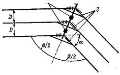
Rice. 1. Scheme of the anchor span of the overhead line and the span of the intersection with the railway.
4. Wooden poles are widely used on overhead lines up to 110 kV inclusive. Wooden poles have also been developed for 220 kV overhead lines, but they are not widely used. The advantages of these supports are low cost (in areas with forest resources) and ease of manufacture. The disadvantage is the susceptibility of wood to decay, especially at the point of contact with the soil. Effective remedy against decay - impregnation with special antiseptics.
Supports are made in most cases composite. The leg of the support consists of two parts of a long (rack ) and short (stepson). The stepson is connected to the rack with two bandages made of steel wire. Anchor and intermediate corner supports for 6-10 kV overhead lines are made in the form of an A-shaped structure.
The intermediate support is a portal having two racks with wind connections and a horizontal traverse. Anchor corner supports for V L 35-110 kV are made in the form of spatial A-P-shaped structures.
5. Metal poles (steel) used on power lines with a voltage of 35 kV and above, rather metal-intensive and require painting during operation to protect against corrosion. Install metal supports on reinforced concrete foundations. The most common design supports 500 kV - guyed portal (Fig. 2). For the 750 kV line, both portal poles on guys and V-shaped poles of the Nabla type with split guys are used. For use on 1150 kV lines under specific conditions, a number of tower designs have been developed - portal, V-shaped, with a cable-stayed traverse. The main type of intermediate supports for 1150 kV lines are V-shaped supports on guys with a horizontal arrangement of wires (Fig. 2). A DC line with a voltage of 1500 (±750) kV Ekibastuz-Center is designed on metal supports (Fig. 2) .
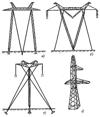
Fig.2. Metal supports:
A - intermediate single-circuit on braces 500 kV;b - intermediate V-shaped 1150 kV;V - intermediate support of 1500 kV direct current overhead line;G - elements of spatial lattice structures
6. Reinforced concrete poles are more durable than wooden poles, require less metal than metal poles, are easy to maintain and therefore are widely used on overhead lines up to 500 kV inclusive. The unification of the structures of metal and reinforced concrete supports for 35-500 kV overhead lines was carried out. As a result, the number of types and designs of supports and their parts has been reduced. This made it possible to mass-produce supports at factories, which accelerated and cheapened the construction of lines.
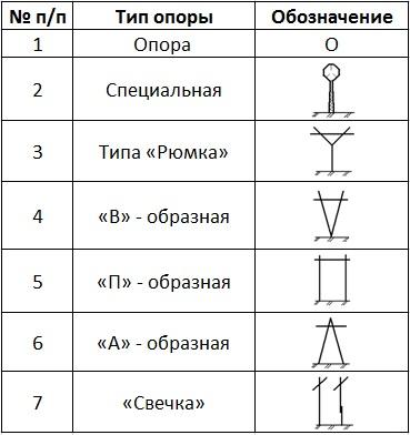
Support types
Overhead power lines. Support structures.
Supports and foundations for overhead power lines with a voltage of 35-110 kV have a significant share both in terms of material consumption and in terms of cost. Suffice it to say that the cost of the mounted support structures on these overhead lines is, as a rule, 60-70% of the total cost of the construction of overhead power lines. For lines located at industrial enterprises and areas immediately adjacent to them, this percentage can be even higher.
Overhead line supports are designed to support line wires at a certain distance from the ground, ensuring the safety of people and reliable operation of the line.
Overhead power line towers are divided into anchor and intermediate. The supports of these two groups differ in the way the wires are suspended.
Anchor supports completely perceive the tension of wires and cables in spans adjacent to the support, i.e. serve to stretch the wires. On these supports, the wires are suspended with the help of hanging garlands. Anchor type supports can be of normal and lightweight construction. Anchor supports are much more complicated and more expensive than intermediate ones, and therefore their number on each line should be minimal.
Intermediate supports do not perceive the tension of the wires or perceive it partially. On the intermediate supports, the wires are suspended with the help of insulators supporting garlands, fig. 1.
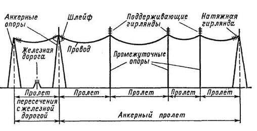
Rice. 1. Scheme of the anchor span of the overhead line and the span of the intersection with the railway
On the basis of anchor supports can be performed end and transposition supports. Intermediate and anchor supports can be straight and angled.
End anchor supports installed at the exit of the line from the power plant or at the approaches to the substation are in the worst conditions. These supports experience one-sided tension of all wires from the side of the line, since tension from the side of the substation portal is insignificant.
Intermediate lines supports are installed on straight sections of overhead power lines to support wires. An intermediate support is cheaper and easier to manufacture than an anchor one, since in normal mode it does not experience forces along the line. Intermediate supports make up at least 80-90% of the total number of overhead line supports.
Angle supports are set at the turning points of the line. At angles of rotation of the line up to 20 °, angled anchor-type supports are used. At angles of rotation of the power line more than 20 ° - intermediate corner supports.
On overhead power lines are used special supports the following types: transpositional- to change the order of the wires on the supports; branch- to carry out branches from the main line; transitional- for crossing rivers, gorges, etc.
Transposition is used on lines with a voltage of 110 kV and above with a length of more than 100 km in order to make the capacitance and inductance of all three phases circuits of overhead power lines are the same. At the same time, the relative position of the wires in relation to each other is consistently changed on the supports. However, such a triple movement of wires is called a transposition cycle. The line is divided into three sections (steps), in which each of the three wires occupies all three possible positions, fig. 2.
Depending on the method of suspension of wires, the supports of overhead lines (VL) are divided into two main groups:
- intermediate supports, on which the wires are fixed in supporting clamps,
- anchor type supports used to tension the wires. On these supports, the wires are fixed in tension clamps.
The distance between the supports of overhead power lines (TL) is called the span, and the distance between the maenadu anchor type supports is called the anchored section (Fig. 1).
In accordance with the requirements of the EIC, the intersection of some engineering structures e.g. railways common use, must be performed on anchor-type supports. At the corners of the line, corner supports are installed, on which the wires can be suspended in support or tension clamps. Thus, the two main groups of supports - intermediate and anchor - are divided into types that have a special purpose.
Rice. 1. Scheme of the anchored section of the overhead line
Intermediate straight supports are installed on straight sections of the line. On intermediate supports with suspension insulators, the wires are fixed in supporting garlands hanging vertically; on intermediate supports with pin insulators, the wires are fixed by wire knitting. In both cases, intermediate supports perceive horizontal loads from wind pressure on the wires and on the support, and vertical loads - from the weight of wires, insulators and the own weight of the support.
With unbroken wires and cables, intermediate supports, as a rule, do not perceive the horizontal load from the tension of wires and cables in the direction of the line and therefore can be made of a lighter design than other types of supports, for example, end supports that perceive the tension of wires and cables. However, to ensure reliable operation of the line, intermediate supports must withstand some loads in the direction of the line.
Intermediate corner supports are installed at the corners of the line with wires suspended in supporting garlands. In addition to the loads acting on the intermediate straight supports, the intermediate and anchor angle supports also perceive loads from the transverse components of the tension of the wires and cables.
At angles of rotation of the power line of more than 20 °, the weight of the intermediate corner supports increases significantly. Therefore, intermediate corner supports are used for angles up to 10 - 20°. At large angles of rotation, anchor angle supports are installed.
Rice. 2. Intermediate supports VL
Anchor supports. On lines with suspension insulators, the wires are fixed in the clamps of the tension garlands. These garlands are, as it were, a continuation of the wire and transfer its tension to the support. On lines with pin insulators, the wires are fixed on anchor supports with reinforced viscous or special clamps that ensure the transfer of the full tension of the wire to the support through pin insulators.
When installing anchor supports on straight sections of the route and suspending wires on both sides of the support with the same tensions, the horizontal longitudinal loads from the wires are balanced and the anchor support works in the same way as the intermediate one, i.e. it perceives only horizontal transverse and vertical loads.
Rice. 3. Anchor-type overhead line supports
If necessary, the wires on one and the other side of the anchor support can be pulled with different tension, then the anchor support will perceive the difference in tension of the wires. In this case, in addition to horizontal transverse and vertical loads, the horizontal longitudinal load will also act on the support. When installing anchor supports at the corners (at the turning points of the line), the anchor corner supports also perceive the load from the transverse components of the tension of the wires and cables.
End supports are installed at the ends of the line. From these supports depart wires suspended on the portals of substations. When hanging wires on the line until the end of the construction of the substation, the end supports perceive the full one-sided tension of the wires and cables of the overhead line.
In addition to the listed types of supports, special supports are also used on the lines: transpositional ones, which serve to change the order of the wires on the supports, branch ones - to make branches from the main line, supports for large crossings over rivers and water spaces, etc.
The main type of supports on overhead lines are intermediate ones, the number of which usually makes up 85-90% of the total number of supports.
According to the design, the supports can be divided into free-standing and guyed supports. Guys are usually made of steel cables. On overhead lines, wooden, steel and reinforced concrete supports are used. Designs of supports made of aluminum alloys have also been developed.
The current power transmission poles are so familiar to our eyes that we do not even think about why there are wooden power transmission poles, concrete power transmission poles and metal power transmission poles. Depending on the purpose of the line, its voltage, the number of wires and cables, their location, climatic and other conditions, various designs of wooden, reinforced concrete or metal supports are used.
So what are power lines (power lines)?
All existing power transmission towers can be classified into wooden, reinforced concrete (RC) and metal. The first thing with which the evolution of power transmission lines began was wooden poles. Such wooden poles were used in the laying of the first power lines, and they still exist on overhead power lines. What tree is used? These are round poles made of pine, less often larch. In Ukraine, such supports are used for power lines with voltages up to 220 kV, and in the USA there are voltage classes of power lines up to 345 kV using wooden poles.
Wooden supports are used in conjunction with reinforced concrete attachments. The supports and attachments are fastened in two places with a bandage made of soft galvanized steel wire with a diameter of 4 mm, the number of turns is 12; diameter 5 mm, number of turns - 10; with a diameter of 6 mm, the number of turns - 8. It is allowed to fasten with a bandage made of non-galvanized wire. The tightening of the bandages is carried out so that all turns of the wire are in close contact with each other and are evenly stretched. The ends of the wire are bent and hammered into a tree to a depth of 20–25 mm.
The greatest advantage of the existing wooden power transmission poles is their cheapness, they are very easy to manufacture, especially if local wood is available! However, a significant drawback is the decay of wood, and therefore the period of their operation of wooden power transmission poles is from 4 to 6 years. Using modern impregnations that prevent decay, the service life is increased up to 25 years!
The simplest design of wooden supports are single poles. There are also other forms of wooden structures for power lines: A - shaped and U-shaped.
Second type of towers existing on power lines These are concrete poles.
What are electric poles?
Electric poles of power lines are brands SV, SK, STs. Such poles are made of metal-reinforced concrete and require less metal, are not subject to corrosion, are more durable than wooden ones, and therefore have become widespread in the construction of power lines. The height of the pole, as stated by the Electrical Installation Rules (PUE), must be at least 5 m, and a maximum of 12, in practice 7-meter concrete supports are used.
According to the method of concrete compaction during manufacture, there are vibrated and centrifuged supports. Steel reinforcement can be unstressed, partially stressed and stressed. The manufacturer supplies the supports with a passport, which indicates the type of supports, the brand of concrete, the type of reinforcement, the date of manufacture and shipment. During transportation and unloading, the supports are monitored so that they are not subjected to shocks, sharp shocks and jerks. It is impossible to unload supports by dropping. It is forbidden to transport reinforced concrete supports and parts on the ground by dragging. They are transported along the route by special support carriers equipped with devices for loading and unloading. 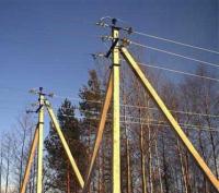
Reinforced concrete supports are installed on power lines with voltages from 35 kV to 380 kV. SV pillars have much higher strength characteristics in comparison with wooden ones. However, there are also disadvantages - the large size and mass of reinforced concrete supports. Therefore, it is difficult and economically unprofitable to transport them to long distances. The service life of reinforced concrete poles for power transmission lines is approximately 50 years.
Last existing type of supports used for high-voltage power lines are metal poles. Such high-voltage structures are made of special high-strength steel, individual elements are fastened to each other with bolts. There are also welded metal structures of power lines.
What are the supports of overhead power lines in Ukraine?
Steel power transmission line poles are of types:
1. Lattice power transmission line supports - are metal carcass, which is assembled from rolled steel with bolts. Lattice-type supports are very economical in transportation due to the compactness of the packages and the relatively low weight of the component parts. To extend the service life of metal structures of overhead lines, there are methods of corrosion protection: they are galvanized or painted with special paints. The service life of galvanized structures of power transmission lines is more than 50 years.
2. Multifaceted power transmission towers are a faceted conical structure made of steel sheet, which is bent in the form of a box and longitudinally welded. There are multifaceted supports that reach 40 meters in height. Masts of this type are considered to be more economically advantageous and reliable in design compared to lattice structures of power transmission lines, and also have better transportability.
 There are transpositional, elevated, lowered, anchor, angular, intermediate, cross and branch poles for power transmission lines. There is also a classification according to the number of suspended wires / circuits. It includes one-, two-, multi-circuit lines. In addition, they differ in the type of construction. There are single-column, free-standing, with braces, etc.
Intermediate straight supports are installed on straight sections of the line. On intermediate supports with suspension insulators, the wires are fixed in supporting garlands hanging vertically; on supports with pin insulators, the wires can be fixed by wire knitting. The existing loads on the intermediate supports of power transmission lines can be divided into horizontal loads from wind pressure on the wires and on the support, and vertical loads - from the weight of wires, insulators and the own weight of the support.
Intermediate corner supports are installed at the corners of the line with wires suspended in supporting garlands. In this case, in addition to the loads acting on the intermediate straight supports of the overhead line, there are additional loads from the transverse components of the tension of the wires and cables. At angles of rotation of the power line of more than 20 °, the weight of the intermediate corner supports increases significantly. At large angles of rotation, anchor-angle supports can be installed.
When installing anchor supports on straight sections of the route and hanging wires on both sides of the high-voltage support, the existing loads from the tension of the wires are balanced and the anchor support works in the same way as the intermediate one, that is, it perceives only horizontal transverse and vertical loads. If necessary, the wires on one and the other side of the support can be stretched with different wire tensions. In this case, in addition to horizontal transverse and vertical loads, a horizontal longitudinal load will act on the existing power transmission line support.
Transmission lines are high voltage (35, 110, 220 and 500 kV) which are used for transportation electrical energy from power plants that produce it to special electrical substations, and low voltage lines (0.4, 6, 10 kV) extending from substations are intended for distribution of electricity between consumers. Power lines (TL) are of 3 types: air, cable and mixed - cable-air.
Choice type of power transmission line supports when designing overhead power lines, it is usually based on the availability of appropriate materials in the area of \u200b\u200bconstruction of the power line, economic feasibility and technical specifications object under construction.