electromagnetic moment a synchronous motor is created by the interaction of the current in the rotor winding with a rotating magnetic field.
Electromagnetic moment M proportional to electromagnetic power:
 (3.40)
Angular synchronous rotation speed.
Substituting in (3.39) the value of electromagnetic power (3.33), we get:
 , (3.41)
i.e. the electromagnetic moment of an induction motor is proportional to the power of electrical losses in the rotor winding.
If the value of the rotor current according to expression (3.28) is substituted into (3.41), then we obtain the formula electromagnetic moment asynchronous machine (Nm):
 (3.42)
Parameters of equivalent circuit of asynchronous machine r 1 , r¢ 2 , x 1 and x¢ 2, included in the expression (3.42), are constant, since their values remain practically unchanged with changes in the load of the machine. The voltage on the stator phase winding can also be considered constant. U 1 and frequency f1. In terms of moment M the only variable is slip s, which for different modes of operation of an asynchronous machine can take on different values in the range from + ¥ to -¥ (see Fig. 3.5).
Consider the dependence of torque on slip M = f(s) at U 1= const, f1= const and constant parameters of the equivalent circuit. This dependency is called mechanical characteristic asynchronous machine. Analysis of expression (3.42), which is an analytical expression of a mechanical characteristic M = f(s), shows that for slip values s= 0 and s= ¥ electromagnetic moment M= 0. From this it follows that the mechanical characteristic M = f(s) has a maximum.
To determine the critical slip s cr, corresponding to the maximum moment, it is necessary to take the first derivative of (3.42) and equate it to zero: . As a result
 (3.43)
Substituting the value of the critical slip (according to 3.43) into the expression for the electromagnetic moment (3.42), after a series of transformations, we obtain the expression for the maximum moment (N m):
 (3.44)
In (3.43) and (3.44) the plus sign corresponds to the motor mode, and the minus sign to the generator mode of operation of the asynchronous machine.
For asynchronous machines general purpose active resistance of the stator winding r1 much less than the sum of inductive reactances: r1< < (x 1 + x¢ 2). Therefore, neglecting the value r1, we obtain simplified expressions for the critical slip
 , (3.45)
and maximum torque (N m)
 (3.46)
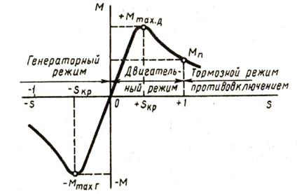
Rice. 3.10. Dependence of operating modes of an asynchronous machine on slip
Analysis of expression (3.44) shows that maximum moment there are more asynchronous machines in the generator mode than in the motor mode ( M max Г > М maxD). On fig. 3.4 shows the mechanical characteristic of an asynchronous machine M = f(s) at U 1= const. This characteristic indicates the zones corresponding to different modes of operation: motor mode (0< s < 1), когда электромагнитный момент M is rotating; generator mode ( - ¥ < s < 0) и тормозной режим противовключением (1 < s < + ¥), когда электромагнитный момент M is inhibitory.
From (3.42) it follows that the electromagnetic torque of an induction motor is proportional to the square of the mains voltage: M ≡ U 1 2. This greatly affects the performance of the motor: even a slight decrease in mains voltage causes a noticeable reduction in the torque of the asynchronous motor. For example, when the mains voltage is reduced by 10% relative to the nominal ( U 1 = 0.9U nom) the electromagnetic torque of the motor is reduced by 19%: М¢ = 0.9 2 M = 0.81M, where M— moment at the rated voltage of the network, and M¢ - torque at reduced voltage.
To analyze the operation of an asynchronous motor, it is more convenient to use the mechanical characteristic M = f(s), shown in fig. 3.5.
 |
Rice. 3.11. Dependence of the electromagnetic torque of an induction motor on slip
When the motor is connected to the network, the stator magnetic field, without inertia, immediately starts rotating with a synchronous frequency n 1, at the same time, the rotor of the motor under the influence of inertia forces at the initial moment of starting remains motionless ( n 2= 0) and sliding s = 1.
Substituting into (3.42) the slip s= 1, we get the expression for the starting torque of an asynchronous motor (N m):
 (3.47)
Under the action of this moment, the rotation of the motor rotor begins, while the slip decreases, and the torque increases in accordance with the characteristic M = f(s). At critical slip s cr moment reaches its maximum value M ma x.
With a further increase in the rotational speed (reduction of slip), the moment M begins to decrease until it reaches a steady value equal to the sum of the counteracting moments applied to the motor rotor: moment XX M0 and useful load torque (torque on the motor shaft) M 2, that is
M \u003d M 0 + M 2 \u003d M st. (3.48)
It should be borne in mind that with slips close to unity (starting mode of the motor), the parameters of the equivalent circuit of an asynchronous motor change their values noticeably. This is mainly explained by two factors: increased magnetic saturation of the toothed layers of the stator and rotor, which leads to a decrease in the inductive leakage resistance x 1 and x 2, and the effect of current displacement in the rotor bars, which leads to an increase in the active resistance of the rotor winding r 2 ¢. Therefore, the parameters of the equivalent circuit of an asynchronous motor used in the calculation of the electromagnetic torque according to (3.42), (3.44) and (3.46) cannot be used to calculate the starting torque according to (3.47).
Static moment M st is equal to the sum of counteracting moments with uniform rotation of the rotor ( n 2= const). Let us assume that the counteracting moment on the motor shaft M 2 corresponds to the rated load of the motor. In this case, the steady state of the engine operation is determined by a point on the mechanical characteristic with coordinates M = M nom and s = s nom, where M nom and s nom— nominal values of electromagnetic torque and slip.
From the analysis of the mechanical characteristic it also follows, that stable operation of an induction motor is possible with slips less than the critical (s< s кр ), i.e., in the section OA of the mechanical characteristic. The fact is that it is in this area that a change in the load on the motor shaft is accompanied by a corresponding change in the electromagnetic torque.
So, if the engine was running in nominal mode ( M nom; s nom), then the moments are equal: M nom \u003d M 0 + M 2. If there is an increase in load torque M 2 up to value M¢ 2, then the equality of the moments will be violated, i.e. M nom< М 0 + М 2 , and the rotor speed will begin to decrease (slip will increase). This will lead to an increase in the electromagnetic torque to a value M¢ \u003d M 0 + M¢ 2, (point B), after which the engine operation mode will again become steady.
If, during the operation of the engine in the nominal mode, the load torque decreases to the value М¢¢ 2, then the equality of the moments will be violated again, but now the torque will be greater than the sum of the opposing ones: M nom > M 0 + M¢¢ 2. The rotor speed will start to increase (the slip will decrease), and this will lead to a decrease in the electromagnetic torque M up to value M¢¢ \u003d M 0 + M¢¢ 2(point C); stable mode of operation will be restored again, but at other values M and s.
The operation of an induction motor becomes unstable during slips s³s cr. So, if the electromagnetic torque of the engine M = M max, and slip s = s cr, then even a slight increase in the load moment M 2, causing an increase in slip s, will lead to a decrease in the electromagnetic torque M. This will be followed by a further increase in slip, and so on, until the slip reaches the value s= 1, i.e. until the motor rotor stops.
Thus, when the electromagnetic torque reaches its maximum value, the limit of stable operation of the induction motor sets in. Therefore, for stable operation of the engine, it is necessary that the sum of the load moments acting on the rotor be less than the maximum torque: M st \u003d (M 0 + M 2)< М тах . But in order for the operation of an induction motor to be reliable and so that random short-term overloads do not cause the motor to stop, it is necessary that it has overload capacity.
Motor overload capacity λ is determined by the ratio of the maximum moment M max to nominal M nom. For induction motors general purpose overload capacity is = 1.7 ÷ 2.5.
You should also pay attention to the fact that the operation of the engine when sliding s< s кр , i.e., in the working section of the mechanical characteristic, is the most economical, since it corresponds to small values of slip, and, consequently, to lower values of electrical losses in the rotor winding P e2 \u003d sP em.
The use of formula (3.35) for calculating the mechanical characteristics of asynchronous motors is not always possible, since the parameters of the equivalent circuit of motors are usually not given in catalogs and reference books, therefore, for practical calculations, a simplified torque formula is usually used. This formula is based on the assumption that the active resistance of the stator winding of an induction motor r1= 0, while:
 (3.49)
Critical slip is determined by the formula:
![]() . (3.50)
. (3.50)
The calculation of the mechanical characteristic is much simpler if it is carried out in relative units  . In this case, the mechanical characteristic equation has the form:
 . (3.51)
The use of a simplified formula (3.51) is most appropriate when calculating the working section of the mechanical characteristic during sliding s< s кр , since in this case the error does not exceed the values allowed for technical calculations. When sliding s > s cr the error can reach 15-17%.
Mechanical characteristics of an asynchronous motor with changes in mains voltage and active resistance of the rotor winding
From (3.42), (3.44) and (3.47) it can be seen that the electromagnetic torque of the induction motor, as well as its maximum and starting values, are proportional to the square of the voltage supplied to the stator winding: M ≡ U 1 2 . At the same time, the analysis of expression (3.43) shows that the value of the critical slip does not depend on the stress U 1 . This gives us the opportunity to plot the mechanical characteristics M = f(s) for different values voltage U 1(Fig. 3.12), from which it follows that fluctuations in the mains voltage U 1 about him nominal value U 1nom are accompanied not only by changes in the maximum and starting torques, but also by changes in the rotor speed.
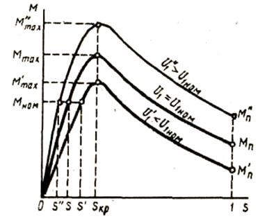 |
Rice. 3.12. Influence of voltage on the type of mechanical characteristic of an induction motor
With a decrease in the mains voltage, the rotor speed decreases (slip increases). Voltage U 1 influences the assignment of the maximum moment M tah, as well as the overload capacity of the engine. So if the voltage U 1 decreased by 30%, i.e. U 1 \u003d 0.7U nom, then the maximum torque of the induction motor will be more than halved:
M¢ max = 0.7 2 M max = 0.49M max.
By how much will the overload capacity of the motor decrease If, for example, at the rated voltage of the network, the overload capacity  , then when the voltage drops by 30%, the overload capacity of the motor
  , i.e. | the engine is not able to carry even the rated load.
As follows from (3.44), the value of the maximum motor torque does not depend on the active resistance of the rotor r¢ 2 . As for the critical slip s cr, then, as can be seen from (3.43), it is proportional to the resistance r¢ 2 . Thus, if in an asynchronous motor the active resistance of the rotor circuit is gradually increased, then the value of the maximum torque will remain unchanged, and the critical slip will increase (Fig. 3.13). In this case, the starting torque of the engine M P increases with increasing resistance r¢ 2 up to some value. In the figure, this corresponds to the resistance r¢ 2 III, at which the starting torque is equal to the maximum. With further increase in resistance r¢ 2 starting torque is reduced.
 |
Rice. 3.13. The influence of the active resistance of the rotor winding on the mechanical characteristics of an asynchronous motor.
Graph analysis M = f(s), shown in fig. 3.13 also shows that changes in rotor resistance r¢ 2 accompanied by changes in rotational speed: with an increase r¢ 2 with constant load moment M st the slip increases, i.e. the speed decreases (points 1, 2, 3 and 4).
The influence of the active resistance of the rotor winding on the shape of the mechanical characteristics of asynchronous motors is used in the design of motors. For example, general purpose asynchronous motors must have a "hard" speed characteristic (see Fig. 3.11), i.e., operate with a small nominal slip. This is achieved by using a rotor winding with low active resistance in the motor. r¢ 2. In this case, the motor has a higher efficiency due to the reduction of electrical losses in the rotor winding ( R e2 \u003d m 1 I¢ 2 2 r¢ 2). Selected value r¢ 2 must provide the motor with the required starting torque.
If it is necessary to obtain a motor with an increased value of the starting torque, the active resistance of the rotor winding is increased. But at the same time, an engine with a large value of nominal slip is obtained, and, consequently, with a lower efficiency.
Considered dependencies M \u003d f (U 1) and M = f(r 2 ") are also of great practical importance when considering the issues of starting and controlling the speed of rotation of asynchronous motors.
Performance characteristics of asynchronous motor
The performance characteristics of an induction motor (Fig. 3.14) are graphically expressed dependences of the rotational speed n 2, efficiency h, useful moment (torque on the shaft) M 2, power factor cosφ 1, and stator current I 1, from useful power R 2 at U 1= const and f1= const.

Rice. 3.14. Performance characteristics of asynchronous motor
speed characteristicn 2 \u003d f (P 2).
Induction motor rotor speed
n 2 \u003d n 1 (1-s).
Sliding on (3.33)
i.e., the slip of the motor, and hence its speed, is determined by the ratio of electrical losses in the rotor to the electromagnetic power R em.
Neglecting the electrical losses in the rotor in idle mode, we can take R e2= 0, and therefore s0 ≈ 0 and n 20 ≈ n 1,. As the load on the motor shaft increases, the ratio (8.1) increases, reaching values of 0.01 ÷ 0.08 at rated load. In accordance with this dependence n 2 = f(P 2) is a curve slightly inclined to the x-axis.
However, with an increase in the active resistance of the rotor r¢ 2 the slope of this curve increases. In this case, changes in rotational speed p 2 during load fluctuations R 2 increase. This is explained by the fact that with increasing r¢ 2 electrical losses in the rotor increase [see. (3.31)].
Mechanical performance M 2 = f(P 2)
The dependence of the useful moment on the motor shaft M 2 from net power R 2 is defined by the expression
 (3.53)
where R 2— useful power, W;
is the angular frequency of rotation of the rotor.
It follows from this expression that if n 2= const, then the graph M 2 \u003d f (P 2) is a straight line. But in an asynchronous motor with increasing load R 2 the rotor speed decreases, and therefore the useful moment on the shaft M 2 with increasing load, it increases somewhat faster than the load, and therefore, the graph M 2 = f(P2) has a curvilinear appearance.
Dependence cosφ 1 = f(P 2)
Due to the fact that the stator current I 1 has a reactive (inductive) component necessary to create a magnetic field in the stator, the power factor of asynchronous motors is less than one.
The lowest value of the power factor corresponds to the XX mode. This is explained by the fact that the current XX I 0 under any load remains virtually unchanged. Therefore, at low motor loads, the stator current is small and largely reactive ( I 1 ≈ I 0). As a result, the phase shift of the stator current relative to the voltage is significant ( φ ≈ φ 0 ), only slightly less than 90° (Fig. 3.15).
The power factor of asynchronous motors in the XX mode usually does not exceed 0.2. With an increase in the load on the motor shaft, the active component of the current increases I 1 and the power factor increases, reaching the highest value (0.80 ÷ 0.90) at a load close to the nominal one.
 |
Fig.3.15. Vector diagram of an induction motor under light load
A further increase in load is accompanied by a decrease cosφ 1, which is explained by the increase in the inductive resistance of the rotor ( x 2s) by increasing the slip, and hence the frequency of the current in the rotor. In order to improve the power factor of asynchronous motors, it is extremely important that the motor always runs, or at least a significant part of the time, with a load close to the rated load.
This can only be ensured if right choice engine power. If the engine runs underloaded for a significant part of the time, then to increase cosφ 1 suitably applied voltage to the motor U 1 decrease.
For example, in motors operating with a delta connection of the stator winding, this can be done by reconnecting the stator windings in a star, which will cause a decrease in phase voltage in time. In this case, the stator magnetic flux, and consequently, the magnetizing current, decreases by about a factor. In addition, the active component of the stator current increases somewhat. All this contributes to an increase in the power factor of the engine.
On fig. 3.16 shows dependency graphs cosφ 1 asynchronous motor from the load when connecting the stator windings with a star (curve 1 ) and a triangle (curve 2).

Rice. 3.16. Addiction cosφ 1 from the load when connecting the stator winding with a star (1) and a delta (2).
Questions for self-examination
1. Explain the principle of operation of an asynchronous machine.
2. Describe the modes of operation of an asynchronous machine.
3. What is called the sliding of an asynchronous machine?
4. Write down the voltage equations for an induction motor?
5. Write down the equations of MMF and currents of the induction motor.
6. Draw the equivalent circuits of an induction motor.
7. Draw a vector diagram of an induction motor.
8. What losses exist in an asynchronous motor? Draw an energy diagram for an induction motor.
9. Write down the formula for the electromagnetic torque of an induction motor.
10. Draw a graph of the mechanical characteristic of an induction motor.
11. How do the mechanical characteristics of an asynchronous motor change depending on the change in the mains voltage and the active resistance of the rotor?
12. Draw the operating characteristics of an induction motor.
Performance characteristics of asynchronous motor
WORK IN ELECTRICAL ENGINEERING
"Performance characteristics of asynchronous motor"
Introduction
An asynchronous electric machine is an alternating current electric machine in which the rotor speed is not equal to the stator magnetic field speed and depends on the load. It is mainly used as an engine and as a generator. The stator has grooves into which a single- or multi-phase (usually three-phase) winding is placed, connected to the AC mains. This winding is designed to create a moving magnetic field, rotating circular - for three-phase machines and pulsating or rotating elliptical - for single-phase machines. The rotor is a rotating part of an electrical machine, also designed to create a magnetic field, which, interacting with the stator field, leads to the creation of an electromagnetic torque that determines the direction of energy conversion. For generators, this moment is of a braking nature, counteracting the torque of the prime mover, which sets the rotor in motion. In engines, on the contrary, this moment is driving, overcoming the resistance of the mechanism driven by the rotor.
An asynchronous generator is an asynchronous electrical machine operating in generator mode. An auxiliary source of electric current of low power and a braking device (in an electric drive).
An asynchronous electric motor is an asynchronous electric machine operating in motor mode. The most common three-phase asynchronous electric motor (invented in 1889 by MO Dolivo-Dobrovolsky). Asynchronous motors are relatively simple in design and reliable in operation, but have a limited speed range and low power factor at low loads. Power from fractions of W to tens of MW.
1. Asynchronous motor
1.1 Frequency of rotation of the magnetic field and rotor
Let n1 is the rotation frequency of the magnetic field. A multi-phase AC system creates a rotating magnetic field, the rotational speed of which per minute is n1=60f1/p, where f1 is the frequency of the current, p is the number of pole pairs formed by each phase of the stator winding.
n2- frequency of rotation of the rotor. If the rotor rotates at a frequency not equal to the frequency rotation of the magnetic field (n2≠n1), then this frequency is called asynchronous. In an asynchronous motor, the workflow can only run at an asynchronous frequency.
During operation, the rotor speed is always less than the field speed.
(n2< n1)
1.2 The principle of operation of an asynchronous motor
In asynchronous motors, a rotating magnetic field is created by a three-phase system when it is connected to an alternating current network. The rotating magnetic field of the stator crosses the conductors of the rotor winding and induces emf in them. If the rotor winding is closed to any resistance or short-circuited, then under the action of the induced emf. current passes. As a result of the interaction of the current in the rotor winding with a rotating magnetic field the stator winding creates a torque, under the influence of which the rotor begins to rotate in the direction of rotation of the magnetic field. To change the direction of rotation of the rotor, it is necessary to swap any two of the three wires connecting the stator winding to the network with respect to the network terminals.
1.3 The device of an asynchronous motor
The stator core is recruited from steel plates, 0.35 or 0.5 mm thick. The plates are stamped with grooves and fixed in the engine frame. The bed is installed on the foundation. In the longitudinal grooves of the stator, the conductors of its winding are laid, which are interconnected so that a three-phase system is formed. To connect the stator windings to a three-phase network, they can be connected in a star or a delta. This makes it possible to turn on the motor in a network with different voltages. For lower voltages (220/127 V), the stator winding is connected in a triangle, for higher voltages (380/220 V) - in a star. The rotor core is also made of steel plates with a thickness of 0.5 mm. The plates are stamped with grooves and assembled into packages that are mounted on the shaft of the machine. A cylinder with longitudinal grooves is formed from the packages, in which the conductors of the rotor winding are laid. Depending on the type of rotor winding, asynchronous machines can be phase and squirrel-cage rotor. Resistance cannot be included in a short-circuited winding. In the phase winding, the conductors are interconnected, forming a three-phase system. windings three phases connected by a star. The rotor winding can be short-circuited or short-circuited. Motors with a squirrel-cage rotor are simpler and cheaper, but motors with a wound rotor have better starting and regulating properties (they are used at high powers). The power of asynchronous motors ranges from several tens of watts to 15,000 kW at a stator winding voltage of up to 6 kV. The disadvantage of asynchronous motors is the low power factor.
1.4 Operation of an asynchronous motor under load
n1 is the frequency of rotation of the stator magnetic field. n2- frequency of rotation of the rotor.
n1 >n2
The stator magnetic field rotates in the same direction as the rotor and slides relative to the rotor with a frequency ns= n1 – n2
The lag of the rotor from the rotating magnetic field of the stator is characterized by slip S= ns / n1, => S = (n1 - n2) / n1
If the rotor is stationary, then n2=0, S=(n1 – n2) / n1, => S = n1 / n1=1
If the rotor rotates synchronously with the magnetic field, then the slip S= 0.
At idle, that is, when there is no load on the motor shaft, the slip is negligible and can be taken equal to 0. The load on the rotor shaft can be, for example, a lathe cutter. It creates braking torque. If the torque and braking torque are equal, the motor will run stably. If the load on the shaft has increased, then the braking torque will become greater than the torque and the rotor speed n2 decrease. According to the formula S =(n1 - n2) / n1 slip will increase. Since the magnetic field of the stator slides relative to the rotor with a frequency ns= n1 – n2, then it will cross the rotor conductors more often, the current and the motor torque will increase in them, which will soon become equal to the braking torque. When the load decreases, the braking torque becomes less than the torque, increases n2 and decreases S. EMF decreases and the rotor current and the torque is again equal to the brake. The magnetic flux in the air gap of the machine remains approximately constant for any change in load.
2. Performance characteristics of asynchronous motor
The performance of an induction motor is dependent
S - slip
n2 - rotor speed
M - developed moment
I1 current consumption
P1 power input
COSφ power factor
From the useful power P2 on the machine shaft.
These characteristics are removed under natural conditions. The current frequency f1 and the voltage U1 remain constant. Only the load on the motor shaft changes.
As the load on the motor shaft increases, S increases. When the engine is idling n2≈n1, and S≈0. At rated load, the slip is typically 3 to 5%.
With an increase in the load on the motor shaft, the rotational speed n2 decreases. However, the change in speed with increasing load from 0 to nominal is very small and does not exceed 5%. Therefore, the speed characteristic of an induction motor is rigid. The curve has a very small slope to the horizontal axis.
Torque M, developed by the engine, is balanced by the braking torque on the shaft Mt and moment М0, going to overcome mechanical losses, that is M \u003d Mt + M0 \u003d P2 /Ω2+ М0, where R2– useful engine power , Ω 2 - angular velocity of the rotor. At idle M= M0. With an increase in load, the torque also increases, and due to a slight decrease in the rotor speed, the increase in torque occurs faster than the useful power on the shaft.
The current I1 consumed by the motor from the network varies unevenly with increasing load on the motor shaft. At idle, the COSφ power factor is small. And the current has a large reactive component. At low loads on the motor shaft, the active component of the stator current is less than the reactive component, so the active component of the current has little effect on the current I1. At high loads, the active component of the stator current becomes larger than the reactive one, and a change in load causes a significant change in current I1.
The graphical dependence of the power consumed by the motor P1 is depicted as an almost straight line, slightly deviating upwards at high loads, which is explained by an increase in losses in the stator and rotor windings with increasing load.
The dependence of the COSφ-power factor on the load on the motor shaft is as follows. At idle, СOSφ is small, about 0.2. Since the active component of the stator current, due to power losses in the machine, is small compared to the reactive component of this current, which creates a magnetic flux. With an increase in the load on the shaft, СOSφ increases, reaching the maximum value of 0.8–0.9, as a result of an increase in the active component of the stator current. At very high loads, there is a slight decrease in COSφ, since as a result of a significant increase in slip and current frequency in the rotor, the reactance of the rotor winding increases.
The efficiency curve η has the same form as in any machine or transformer. At idle, efficiency = 0. With an increase in the load on the motor shaft, the efficiency increases sharply, and then decreases. The efficiency reaches its highest value at such a load, when the power losses in steel and mechanical losses, which do not depend on the load, are equal to the power losses in the stator and rotor windings, which depend on the load.
Similar abstracts:
Varieties of asynchronous executive micromotors: with a hollow non-magnetic and magnetic rotor; with a short-circuited winding like a squirrel wheel. Scheme of a half-closed groove of the magnetic circuit. Creation of a rotating magnetic field by a two-phase stator.
The device of a three-phase asynchronous machine, its main elements, modes and principle of operation, the history of creation and application on present stage. The procedure and conditions for obtaining a rotating magnetic field. The dependence of the electromagnetic torque on slip.
Determination of the total moment of inertia of the gearbox, winch, and load reduced to the motor shaft. Calculation of the moment of resistance reduced to the shaft during ascent, descent. The value of the power on the gearbox shaft. The reason for the difference in power when lifting and lowering the load.
Calculation and design of the motor, selection of main dimensions, calculation of the stator winding. Calculation of the dimensions of the tooth zone of the stator and the choice of the air gap. Engine modeling in the MatLab Power System Blockset environment, as well as with nominal mode parameters.
Main and backup protection of the turbogenerator.
Device and conditional image of synchronous three-phase machine. The location of the poles of the magnetic field of the stator and rotor. Dependence of the electromagnetic torque of a synchronous machine on the angle. the scheme of inclusion of the synchronous motor at dynamic braking.
General information about asynchronous machines(two-winding electrical machines alternating current). The design of active parts, bearing assemblies, the input device of an asynchronous micromotor 4AA50V2, the principle of its operation, areas of application and significance.
Designing a three-phase asynchronous electric motor with squirrel-cage rotor. Choice of motor analogue, dimensions, configuration, magnetic circuit material. Determination of the stator winding coefficient, mechanical calculation of the shaft and rolling bearings.
Calculation of an asynchronous motor with a squirrel-cage rotor. Choice of main sizes. Calculation of the dimensions of the tooth zone of the stator and air gap, rotor, magnetizing current. Operating mode parameters. Calculation of losses, operating and starting characteristics.
General information about asynchronous machines. General information about the modes of operation of an asynchronous motor. Analytical and graphical definition of operation modes of an asynchronous reconstruction machine.
Features of the development of an asynchronous electric motor with a squirrel-cage rotor type 4А160S4У3 based on a generalized machine. Calculation of the mathematical model of an asynchronous motor in the form of Cauchy 5. Adequacy of the model of direct start of an asynchronous motor.
Method for calculating the magnetic circuit synchronous generator, the choice of its dimensions and configuration, the construction of the characteristics of the magnetization of the machine. Determination of winding parameters, performance of thermal and ventilation calculations, assembly drawing of the generator.
Inadmissibility of multiple asynchronous start synchronous motor, which leads to a significant voltage drop in the supply system, to the occurrence of significant dynamic forces in the frontal parts of the stator winding and thermal aging of the insulation.
Construction of the load diagram of the actuator. The choice of elements of the power circuit. Calculation of mechanical characteristics. Assessing the need for speed feedback. Determination of the average efficiency of the system. Transient processes in the drive.
General information about devices automatic regulation excitation of synchronous machines. Factors affecting the voltage and power supply circuit. Current Compounding Device: Necessary Changes in the Characteristics of a Compounding Machine.
Motor magnetic circuit. Dimensions, configuration, material. Stator core, rotor and pole piece. Calculation of the magnetic circuit. Air gap, teeth and stator back. Active and inductive reactance stator windings for steady state.
WORK IN ELECTRICAL ENGINEERING
"Performance characteristics of asynchronous motor"
Introduction
An asynchronous electric machine is an alternating current electric machine in which the rotor speed is not equal to the stator magnetic field speed and depends on the load. It is mainly used as an engine and as a generator. The stator has grooves into which a single- or multi-phase (usually three-phase) winding is placed, connected to the AC mains. This winding is designed to create a moving magnetic field, rotating circular - for three-phase machines and pulsating or rotating elliptical - for single-phase machines. The rotor is a rotating part of an electrical machine, also designed to create a magnetic field, which, interacting with the stator field, leads to the creation of an electromagnetic torque that determines the direction of energy conversion. For generators, this moment is of a braking nature, counteracting the torque of the prime mover, which sets the rotor in motion. In engines, on the contrary, this moment is driving, overcoming the resistance of the mechanism driven by the rotor.
An asynchronous generator is an asynchronous electrical machine operating in generator mode. Auxiliary source electric current low power and braking device (in the electric drive).
An asynchronous electric motor is an asynchronous electric machine operating in motor mode. The most common three-phase asynchronous electric motor (invented in 1889 by MO Dolivo-Dobrovolsky). Asynchronous motors are relatively simple in design and reliable in operation, but have a limited speed range and low power factor at light loads. Power from fractions of W to tens of MW.
1. Asynchronous motor
1.1 Frequency of rotation of the magnetic field and rotor
Let n 1 is the rotation frequency of the magnetic field. A multi-phase AC system creates a rotating magnetic field, the rotational speed of which per minute is n1=60f1/p, where f1 is the frequency of the current, p is the number of pole pairs formed by each phase of the stator winding.
n 2 - frequency of rotation of the rotor. If the rotor rotates with a frequency not equal to the frequency of rotation of the magnetic field (n2≠n1), then this frequency is called asynchronous. In an asynchronous motor, the workflow can only run at an asynchronous frequency.
During operation, the rotor speed is always less than the field speed.
( n 2< n 1)
1.2 The principle of operation of an asynchronous motor
In asynchronous motors, a rotating magnetic field is created by a three-phase system when it is connected to an alternating current network. The rotating magnetic field of the stator crosses the conductors of the rotor winding and induces emf in them. If the rotor winding is closed to any resistance or short-circuited, then under the action of the induced emf. current passes. As a result of the interaction of the current in the rotor winding with the rotating magnetic field of the stator winding, a torque is created, under the influence of which the rotor begins to rotate in the direction of rotation of the magnetic field. To change the direction of rotation of the rotor, it is necessary to swap any two of the three wires connecting the stator winding to the network with respect to the network terminals.
1.3 The device of an asynchronous motor
The stator core is recruited from steel plates, 0.35 or 0.5 mm thick. The plates are stamped with grooves and fixed in the engine frame. The bed is installed on the foundation. In the longitudinal grooves of the stator, the conductors of its winding are laid, which are interconnected so that a three-phase system is formed. To connect the stator windings to three-phase network they can be star or delta connected. This makes it possible to turn on the motor in a network with different voltages. For lower voltages (220/127 V), the stator winding is connected in a triangle, for higher voltages (380/220 V) - in a star. The rotor core is also made of steel plates with a thickness of 0.5 mm. The plates are stamped with grooves and assembled into packages that are mounted on the shaft of the machine. A cylinder with longitudinal grooves is formed from the packages, in which the conductors of the rotor winding are laid. Depending on the type of rotor winding asynchronous machines may be with phase and short-circuited rotor. Resistance cannot be included in a short-circuited winding. In the phase winding, the conductors are interconnected, forming a three-phase system. The windings of the three phases are connected by a star. The rotor winding can be short-circuited or short-circuited. Motors with a squirrel-cage rotor are simpler and cheaper, but motors with a wound rotor have better starting and regulating properties (they are used at high powers). The power of asynchronous motors ranges from several tens of watts to 15,000 kW at a stator winding voltage of up to 6 kV. The disadvantage of asynchronous motors is the low power factor.
1.4 Operation of an asynchronous motor under load
n 1 is the frequency of rotation of the stator magnetic field. n 2 - frequency of rotation of the rotor.
n 1 > n 2
The stator magnetic field rotates in the same direction as the rotor and slides relative to the rotor with a frequency n s = n 1 – n 2
The lag of the rotor from the rotating magnetic field of the stator is characterized by slip S = n s / n 1, => S = ( n 1 – n 2) / n 1
If the rotor is stationary, then n 2 =0, S = ( n 1 – n 2) / n 1, => S = n 1 / n 1 =1
If the rotor rotates synchronously with the magnetic field, then the slip S= 0.
At idle, that is, in the absence of a load on the motor shaft, the slip is negligible and can be taken equal to 0. The load on the rotor shaft can be, for example, a cutter lathe. It creates braking torque. If the torque and braking torque are equal, the motor will run stably. If the load on the shaft has increased, then the braking torque will become greater than the torque and the rotor speed n 2 decrease. According to the formula S = ( n 1 – n 2) / n 1 slip will increase. Since the magnetic field of the stator slides relative to the rotor with a frequency n s = n 1 – n 2, then it will cross the rotor conductors more often, the current and the motor torque will increase in them, which will soon become equal to the braking torque. When the load decreases, the braking torque becomes less than the torque, increases n 2 and decreases S . EMF decreases and the rotor current and the torque is again equal to the brake. The magnetic flux in the air gap of the machine remains approximately constant for any change in load.
2. Performance characteristics of asynchronous motor
The performance of an induction motor is dependent
S - slip
n2 - rotor speed
M - developed moment
I1 current consumption
P1 power input
COSφ power factor
From the useful power P2 on the machine shaft.
These characteristics are removed under natural conditions. The current frequency f1 and the voltage U1 remain constant. Only the load on the motor shaft changes.
As the load on the motor shaft increases, S increases. When the engine is idling n2≈n1, and S≈0. At rated load, the slip is typically 3 to 5%.
With an increase in the load on the motor shaft, the rotational speed n2 decreases. However, the change in speed with increasing load from 0 to nominal is very small and does not exceed 5%. Therefore, the speed characteristic of an induction motor is rigid. The curve has a very small slope to the horizontal axis.
Torque M, developed by the engine, is balanced by the braking torque on the shaft Mt and moment M 0 , going to overcome mechanical losses, that is M= Mt + M 0 =P 2 /Ω 2 + M 0 , where R 2 – useful engine power , Ω 2 - angular velocity of the rotor. At idle M=M 0. With an increase in load, the torque also increases, and due to a slight decrease in the rotor speed, the increase in torque occurs faster than the useful power on the shaft.
The current I1 consumed by the motor from the network varies unevenly with increasing load on the motor shaft. At idle, the COSφ power factor is small. And the current has a large reactive component. At low loads on the motor shaft, the active component of the stator current is less than the reactive component, so the active component of the current has little effect on the current I1. At high loads, the active component of the stator current becomes larger than the reactive one, and a change in load causes a significant change in current I1.
The graphical dependence of the power consumed by the motor P1 is depicted as an almost straight line, slightly deviating upwards at high loads, which is explained by an increase in losses in the stator and rotor windings with increasing load.
The dependence of the COSφ-power factor on the load on the motor shaft is as follows. At idle, СOSφ is small, about 0.2. Since the active component of the stator current, due to power losses in the machine, is small compared to the reactive component of this current, which creates a magnetic flux. With an increase in the load on the shaft, СOSφ increases, reaching the maximum value of 0.8–0.9, as a result of an increase in the active component of the stator current. At very high loads, there is a slight decrease in COSφ, since as a result of a significant increase in slip and current frequency in the rotor, the reactance of the rotor winding increases.
The efficiency curve η has the same form as in any machine or transformer. At idle, efficiency = 0. With an increase in the load on the motor shaft, the efficiency increases sharply, and then decreases. Greatest value The efficiency is reached at such a load, when the power losses in steel and mechanical losses, which do not depend on the load, are equal to the power losses in the stator and rotor windings, which depend on the load.
Electromagnetic moment
.
Complete mechanical power engine
is created as a result of rotation of the rotor with an angular velocity ω 2 under the action of the moment M em i.e.
P fur \u003d M em ω 2 (2.19)
This power can be determined from the equivalent circuit as electric power, which stands out on the conditional load resistance R well ", multiplied by the number of stator phases:
P fur = m 1 (I 2 ") 2 R 2 " (1-s) / s (2.20)
Based on (2.19) and (2.20), taking into account (2.8), we can write
M em \u003d (m 1 (I 2 ") 2 R 2 " / s) / ω 1 (2.21)
When calculating the moment according to the formula (2.21), the current I 2" is determined by the equivalent circuit (Fig. 2.10) for the corresponding slip.
Formula (2.21) can be transformed by substituting into it the expression for the current I 2", obtained under certain assumptions from the equivalent circuit
M em \u003d (m 1 U 1 R 2 "/s) / ω 1 ((R 1 + CR 2 / s) 2 + (x 1 + Cx 2 ") 2) (2.22)
Coefficient C, which enters formula (2.22), is the modulus complex coefficient FROM
= 1 + (z 1 /z m) that appears during the transformation. The assumption is to take into account only the modulus of the coefficient FROM
, because its argument in real machines is very small. In real machines (excluding micromachines) FROM
= 1.03–1.08 and at qualitative analysis sometimes take FROM
=
1.
Expression (2.21) can also be transformed by expressing the active voltage drop in the rotor I 2 "R 2" / s through EMF based on formulas (2.15) and (2.16)
I 2 "R 2" /s \u003d E 2 "cos ψ 2 (2.23)
Substituting (2.23) into (2.21) and performing transformations, taking into account (2.18) and (2.12), we obtain
M em \u003d k F m I 2 "cos ψ 2 (2.24)
where k- constructive coefficient.
As can be seen from (2.24), the electromagnetic moment is directly proportional to the main magnetic flux F m and the active component of the rotor current I 2" cos ψ 2.
Torque formulas (2.21), (2.22) and (2.24) are obtained for the motor mode, but they are also valid for other modes, taking into account the sign and range of slip values s. The dependence of the electromagnetic torque on slip is graphically presented in fig. 2.11 (solid line).
This type of characteristic is easily explained using formulas (2.24), (2.15), and (2.16). With increasing slip, the rotor current I 2 continuously increases, but becomes more and more inductive - decreases cos ψ 2 as the frequency of currents in the rotor increases and, accordingly, its inductive resistance. As a result, the active component of the rotor current and, accordingly, the electromagnetic torque first increase and then begin to decrease.
The slip at which the moment reaches the maximum value M max is called critical and is denoted by scr. To determine scr, it is necessary, using expression (2.22), to take the derivative dM em /ds and equate it to zero. The solution of the resulting equation has the form
s cr \u003d ±C R 2 " / √ (R 1 " + 2) (2.25)
Taking in the first approximation C 1 ≈ 1 and R 1 ≈ 0, we get
s cr = ±R 2 " /(x 1+x2") (2.26)
Most induction motors require high efficiency. Therefore, the active resistance of the windings, in particular R 2 , which determines the level of electrical losses in the rotor, tend to be small. In this case, the critical slip lies in the range .
We substitute (2.25) into (2.22) and obtain the expression for the maximum moment:
M max = ± m 1 U 1 2 /2 ω 1 C [± R 1 + √(R 1 2 +(x 1 + Cx 2) 2)] (2.27)
The "+" sign refers to the motor mode, "-" - to the generator mode.
As you can see, the maximum moment is proportional to the square supply voltage, does not depend on the active resistance of the rotor circuit R2 and occurs with the greater slip, the greater the active resistance of the rotor circuit (Fig. 2.11, dash-dotted line, R2B >R2A).
Starting torque engine M p is determined by expression (2.22) for s=1. Meaning M p proportional to the square of the supply voltage and increases with increasing R2(see Fig. 2.11), reaching a maximum at s cr =1.
The rated slip snom, corresponding to the rated torque Mnom, increases with increasing R 2 . This is accompanied by an increase in electrical losses in the rotor circuit and a decrease in efficiency. For asynchronous motors with low critical slip, S nom = 0.02 - 0.06.
Equilibrium equation of moments on the motor shaft.
The electromagnetic moment developed by the engine overcomes the load moment M n applied to the engine shaft and the engine's own moment of resistance M 0 (idling torque), determined by mechanical and additional losses in the engine. The resulting moment determines the value and sign of the rotor acceleration:
dω / dt \u003d (M em - M 0 - M n) / J (2.28)
Where J- the moment of inertia of the rotating parts - the rotor and the load.
This is a differential equation of motion of an electric drive, consisting of a motor and a load, converted to the form
M em \u003d M 0 + M n + J (dω / dt) (2.29)
called the equation of equilibrium of moments on the motor shaft.
In this equation:
M 0 + M n \u003d M st- static moment of resistance,
J(dω/dt)= M dyn is the dynamic moment of resistance.
Electromagnetic moment M uh minus moment M0 called the useful or torque on the shaft and denote M2. From equations (2.28) and (2.29) it follows that:
1) if M uh = M st, then dω/dt = 0, ω
= const i.e. the engine operates in a steady state (static) mode, while M2 = M n;
2) if M uh> M st, then the angular velocity of the rotor increases, i.e. the engine operates in a transient (dynamic) mode;
3) if M uh< M st, then the angular velocity of the rotor decreases, i.e. the engine is running in transient mode.
AT general case When compiling the equation for the equilibrium of moments, one should take into account the signs of the moments, which are determined by the direction of action of the moments with respect to the positive direction of rotation. If the motor generates an electromagnetic torque acting in a positive direction, then the torque is considered positive ( M uh> 0). If the motor goes into braking mode, its torque starts to act in the opposite direction ( M uh< 0).
The static moments of resistance created by the working mechanism and the transmission device are of two types: reactive and active. The reactive moments of resistance are always directed against the direction of rotation, i.e. are inhibitory ( M st< 0). К реактивным
моментам относятся моменты сил трения, в том числе в самом двигателе, моменты
сопротивления при резании металла на обрабатывающих станках и т.д. Активный момент
всегда действует в одном и том же направлении, независимо от направления вращения,
т.е. может либо препятствовать движению (M st> 0), or contribute to it ( M st< 0). К активным
моментам относятся моменты сил тяжести, сил упругости пружин и т.д.
Mechanical characteristics.
The equation of the natural mechanical characteristic of an induction motor is the expression (2.21) or (2.22) with the slip S replaced by the angular velocity ω 2 according to (2.8) for U 1 = const. The characteristic graph is shown in fig. 2.12, a.

Fig.2.12
Let us evaluate the mechanical characteristic in terms of stability, rigidity and linearity.
It is considered that the motor in an open drive operates stably if, after the disturbance is removed, it automatically returns to the initial operating point on the mechanical characteristic. Mechanical characteristic motor is the dependence of the angular velocity of the rotor on the electromagnetic torque: ω 2 \u003d f (M em).The mechanical characteristic of the load is the dependence of the static moment of resistance on the motor shaft on the angular velocity: M st \u003d f (ω 2).
Theoretically, the steady-state operation of the engine is possible at points A 1 and A 2, where M uh=M st.A. Let the engine run with a load M st.A \u003d const at the point A 1 and a perturbation appears, leading to an increase in the angular velocity??. The motor then generates a torque corresponding to the point A 1", and the load is the moment of resistance corresponding to the point A 1. Wherein M uh<M st, in accordance with the moment equilibrium equation, the angular velocity ω 2 decreases and the engine returns to the point A 1. Return to point A 1 will also occur with a negative increment of speed (point A 1""). If the engine is running with load at point A 2, then with a disturbance leading to an increase in speed, the engine creates a torque corresponding to the point A 2", and the load is the moment of resistance corresponding to the point A 2. Wherein M uh>M st and the angular velocity continues to increase, the engine moves away from the point A 2. Return to point A 2 does not occur even with a negative increment of speed (point A 2""). In this case, the speed will continue to decrease until the engine stops.
Therefore, at the point A 1 the engine runs steadily, and at the point A 2- unstable. In the general case, a formal sign of stable operation of the engine is the inequality
(dM em /dω 2)< (dM ст /dω 2) (2.30)
With a load moment that does not depend on speed, i.e. at M st \u003d cons t, this inequality takes the form
(dω 2 /dM em)< 0 (2.31)
Based on the concept of the stability of the engine in an open drive, it is customary to call the mechanical characteristic of the engine stable if it ensures stable operation of the engine at M st \u003d const.
If we use the formal stability criterion (2.31), then it is easy to show that for M st \u003d const stable operation of the engine is ensured only in the area from ω 1 before ω 2cr. Plot from ω 2cr up to 0 is unstable. The operating range of torques and speeds of electric drives with asynchronous motors is selected within the stable part of the mechanical characteristics of the motor. Rated load point M nom is located on the working area in such a way that the overload capacity K m \u003d M max / M nom \u003d 1.7 -3.5. With low rotor resistance R2 critical speed ω 2cr \u003d (0.8 - 0.9) ω 1 and the work area is hard. The mechanical characteristic is generally non-linear, but its working area is close to linear.
Within the working area, the engine self-regulates. The increase in the moment of resistance on the motor shaft from M st.v before M st.s leads to a decrease in the angular velocity of the rotor from ω 2v before ω 2s, an increase in the EMF and current induced in the rotor by a rotating field, and, accordingly, an increase in the electromagnetic moment to a value equal to the new value of the moment of resistance (transition from the point AT exactly FROM on the mechanical characteristic).
Operating characteristics
.
The performance characteristics of an induction motor are the dependences of the angular velocity of the rotor ω 2, useful moment M 2, efficiency η
, power factor cos φ 1(φ 1- phase shift between U 1 and I 1) and stator current I 1 from useful power P2 at U 1 = U nom and f1 = f nom(Fig. 2.12, b). Performance characteristics can either be taken experimentally or calculated using an equivalent circuit.
When switching from the x.x. (motor is not loaded) to the nominal load mode, the angular velocity of the rotor decreases slightly, because ω 2 \u003d (1 - s) ω 1, a S nom, as noted, is units of percent. Accordingly, a useful moment M 2 \u003d P 2 / ω 2 increases according to a law close to linear. The change in stator current is determined by the response of the rotor; the relatively large value of the current at idle is due to the presence of an air gap. Current x.x. mostly inductive, and correspondingly low cos φ 10- about 0.1 - 0.2. As the load increases, the consumed active electric power increases and cos φ 1 grows - its maximum value reaches 0.7 - 0.9. The current retains an active-inductive character ( φ 1>0) and the supply network is loaded with reactive current. Engine efficiency η \u003d R 2 / R 1, where R 1- active electrical power consumed by the motor. With symmetrical power R 1 \u003d m 1 U 1 I 1 cos φ 1, where U 1, I 1– phase voltage and current. Dependence of efficiency on power P 2 \u003d P 1 -Δp e -Δp m -Δp fur has the same appearance as the transformer, because in the engine, losses are also divided into fixed and variable losses. For machines of small and medium power, the maximum value of efficiency η
= 0.7 - 0.9, while lower values refer to motors of lower power, which have a relatively higher active resistance of the windings.
We advise you to read
, diagnosis, treatment Treatment of urogenital chlamydia") Chlamydia urogenital - description, causes, symptoms (signs), diagnosis, treatment Treatment of urogenital chlamydia
Chlamydia urogenital - description, causes, symptoms (signs), diagnosis, treatment Treatment of urogenital chlamydia The benefits and significance of hydroamino acid threonine for the human body L threonine what
 To wait or not to wait for a guy from the army For what reason can they be commissioned from the army
 Baked apples with cottage cheese Baked apples with cottage cheese

