Nowadays, many devices are powered by remote power supplies - adapters. When the device stopped showing signs of life, you first need to determine in which part the defect is, in the device itself, or the PSU is faulty.
First of all, an external examination. You should be interested in traces of a fall, a broken cord ...
After an external examination of the device being repaired, the first thing to do is to check the power supply, what it gives out. It doesn't matter if it's a built-in power supply or an adapter. It is not enough just to measure the supply voltage at the PSU output. Need a small load a. Without load it can show 5 volts, under light load it will already be 2 volts.
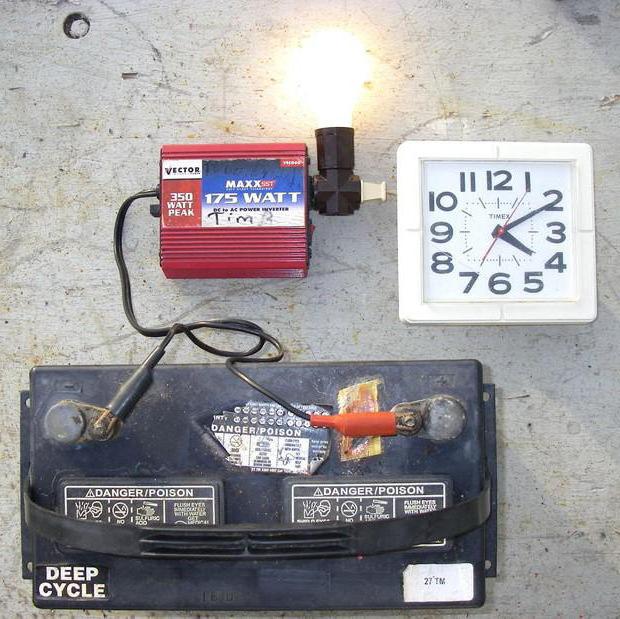
An incandescent lamp for a suitable voltage copes well with the role of the load.. Voltage is usually written on adapters. For example, take the power adapter from the router. 5.2 volts 1 amp. We connect a light bulb 6.3 volts 0.3 amperes, and measure the voltage. A light bulb is enough for a quick check. Lit up - the power supply is working. It is rare that the voltage is very different from the norm.
A lamp for a higher current may prevent the power supply from starting, so a low-current load is sufficient. I have a set of different lamps hanging on the wall for testing.
1 and 2 to test computer power supplies, more power and less, respectively.
3
. Small lamps 3.5 volts, 6.3 volts for testing power adapters.
4
. car lamp at 12 volts to test relatively powerful 12 volt power supplies.
5
. Lamp 220 volts for testing television power supplies.
6
. Two garlands of lamps are missing in the photo. Two at 6.3 volts, for testing 12 volt PSUs, and 3 at 6.3 for testing laptop power adapters with a voltage of 19 volts.
If there is a device, it is better to check the voltage under load.
If the light is not on, it is better to first check the device with a known-good PSU, if one is available. Because power adapters are usually made non-separable, and for repair it will have to be opened. You can't call it demolition.
An additional sign of a power supply failure can be a whistle from the PSU or the powered device itself, which usually speaks of dry electrolytic capacitors. Tightly closed cases contribute to this.
By the same method, the power supplies inside the devices are checked. In older TVs, the 220 volt lamp is soldered instead line scanning, and by the glow you can judge its performance. In part, the lamp-load is also connected due to the fact that some power supplies (built-in) can produce much more voltage than expected without load.
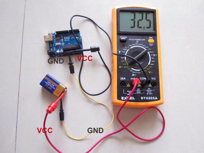
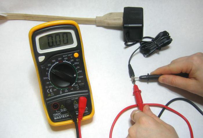
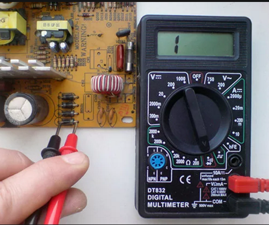
A multimeter is a device with which the voltage, current, resistance is measured, and the wires are “ringed”. That is, this device is quite in demand. Moreover, as practice shows, it is quite popular not only in industry, but also in everyday life.
But before proceeding with the necessary measurements, it should be noted that the multimeter is not a completely harmless device. If used incorrectly, you can not only easily disable it, but also cause serious harm to your health. This is especially true when you need to take measurements when high voltage or high current. You can not only immediately burn the multimeter, but also get a serious electrical injury.
That is why, before you start using the multimeter, you need to practice on power sources with low current strength, such as batteries. Also, do not neglect the instructions for the device.
Varieties of multimeters
First you need to know that multimeters are digital and analog (pointer, even among electricians they are known as "tseshka"). The latter have been known to electricians for a long time, but it is quite difficult to use them without special knowledge and practice.
- you need to be able to understand the scales of the device, which are several on the dial multimeter;
- the device should be held in such a position when the arrow on it will not “walk” along the scale.

That is why, if possible, it is better to use a digital multimeter. We will also consider examples using a digital device, since it is quite difficult to learn how to work with analog multimeters on your own.
There are a lot of varieties of digital multimeters, but the principle of their operation is similar to each other - the difference is only in the number of functions of the device. Accordingly, the price also depends on the functionality of the multimeter, so before you buy it, decide what you need it for.
The multimeter consists of:
- the device itself;
- two probes (black and red);
- power supply (Krona 9 V battery).
So, what are the features of using this measuring device and how to check amps with a multimeter?
Instruction
In order to measure the current strength in the circuit, it is necessary to connect the device to it in series. At the same time, on the multimeter itself, it is necessary to insert a red probe into the socket on the device with the inscription mA, and black - into com. Serial connection means that the circuit must be broken and each probe is connected to a different wire, i.e. the device must be connected between two power sources. But since you are measuring current, which is simply not possible with power sources, you need to include some device in the circuit, for example, an ordinary light bulb, placing it in the circuit immediately after the power source.
If you measure the AC current, then the maximum value of the AC current is set on the device (the A~ icon - note that it is very similar to the DC icon (A-), so be careful). And only after that you can start measuring.
Before checking amps with a multimeter, make sure that the measured current will not be too high, as such measurements can be unsafe due to the small section of the probe wires. The latter may not withstand high loads. Experts recommend taking measurements at a current value of more than 10 A with electrical clamps.
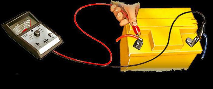
Checking the battery with a multimeter
The test must only be carried out under load. It is impossible to check how many amperes are in the battery with a multimeter, only using the internal capacity of the battery because of its small size - the figures obtained will not display the true numbers.
The tester can measure not only the operating current, but also the battery leakage current. Before checking with a multimeter how many amperes the leakage current is, it must be remembered that it can reach up to several amperes. Therefore, it is necessary to set the measurement limits on the device correctly, preferably up to 10 A.
In practice, before checking the amperes on the battery with a multimeter, you should remove the positive wire from the battery and include it in the resulting gap measuring device. After that you need:
- select the mode on the multimeter for measuring the current strength;
- fix the wires with crocodiles and pull out the fuses one by one, which are responsible for the electronic module in the car.
With some practice, you will not only know how to check amps with a multimeter, but you can easily find the causes of leakage without contacting a service center.
Charger check
Before answering the question: “How to check amps with a multimeter on a charger?”, You need to know that you can measure, in principle, any charge. It can be from phones, tablets, memory for car battery etc.
phone charger
Such measurements are most often necessary when it is necessary to identify the cause of a memory malfunction. It should be noted that the current strength on the chargers of phones, tablets, etc. differs slightly and is usually indicated on the charger itself with a sticker or marking. But if for some reason there is no such inscription, then you can check this indicator with a multimeter.
The principle of measuring the current strength in the charger may differ only in that, due to the small size of the contacts on the connector, it is rather difficult to connect the multimeter probes to them. To do this, you must carefully insert ordinary steel sewing needles into the contacts and connect the multimeter probes to them. If this also fails, then the only way out will be to open the case of the charger in order to connect the probes directly to the terminals of the charger in the place where the ends of the electric cord are soldered.
Charger for car battery
Before talking about how to check amps with a multimeter for a charger for a car battery, you need to know what it is for.
The optimal value of the charging current of such a charger is 10% of the car battery capacity. A larger value will allow you to charge the battery faster, but will negatively affect the battery itself and significantly reduce its use time.
When purchasing such a charger in a store, all parameters are written on the charger itself. But such a charge, with minimal knowledge, can be done independently. In this case, you will need a multimeter. Also, this measuring device will come in handy if the charger fails.
It should be said that when measuring the current strength of any chargers, it is necessary to include any load in the circuit (for example, an ordinary light bulb). Also, do not forget that often the memory issues D.C., so the multimeter knob must be set to the correct position (A-).
Checking the power supply
How to check amps with a multimeter on a power supply? This is also done to break with mandatory application loads. The principle itself differs little from checking other sources. It should only be noted that PSUs have a fairly large power, so measurements should be carried out quickly, avoiding heating of the wires of the multimeter probes.
As we can see, a multimeter can be very useful in everyday life and is in demand in completely different areas, so obtaining the most minimal knowledge on its use will not be superfluous at all.
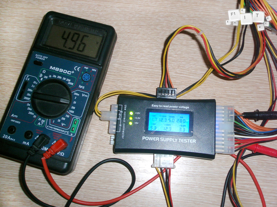
Your attention is offered ways to control the total power consumed by the computer's power supply and the compliance of the load currents of each secondary voltage source with the nominal values.
If you have any doubts about the appropriateness of the parameters of the power supply and the power required for normal operation equipment installed in the system unit, it is proposed to perform control measurements.
Measurements according to the proposed method will help to conclude that the power of your power supply matches the needs of the equipment and the power reserve for further upgrading the hardware of the system.
The maximum power that the power supply can be loaded with is indicated in its passport data (I have this sticker on it).
The actual total load on the power supply can be measured with an AC ammeter. An AC ammeter is found in many small testers, but not all. Most cheap testers have an AC current limit of 3 amps, the maximum measurable power in this case is 650 watts. In principle, it is sufficient for typical power supplies. We focus on the value of the nameplate power of the power supply - if more than 650 watts, then you need to use a tester for 10 amperes, for example, if less, then you can use a tester with an alternating current measurement limit of 3 amperes.
We do the initial measurements like this.
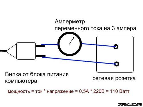
We set the tester to the maximum measurement limit of alternating current and turn it on in series between the computer's power plug and the outlet, as shown in the figure.
Caution on the bare ends of the connections!!!
You need to expand and fix them so that they do not hang out and do not accidentally touch. All wires must be securely connected to the plug, socket and tester. If during the measurement process the contacts are unreliable, you can get a series of withdrawals - voltage supply to the computer, which is extremely contraindicated for it. And, of course, do not touch with your hands. Well, if the socket is with a switch, then the circuit can be assembled with the socket turned off, and then remove your hands and gently turn it on.
You can use the carrier, assemble the circuit on the carrier turned off, fix everything, check the reliability of the contacts, then turn on the carrier in the outlet.
Having assembled the circuit, we turn on the computer in a regular way. We are waiting for the current mode to be established, it will be after loading.
We take tester readings. We define power as the product of current in amperes and voltage in volts (the voltage in the network is usually 220 volts, but it can be slightly higher or slightly lower, you can measure it with the same tester by switching it to voltmeter mode AC voltage with a measurement limit of more than 220 volts).
This will be the power consumed by the unit, with the hardware connected and taking into account all the losses for converting the mains voltage into the supply voltage of the system nodes. The power measured immediately after loading is the power consumed by the computer in the minimum mode (booting the OS and waiting for user actions), if in this mode you see an overload, the power supply is faulty or not suitable for your hardware configuration.
In order to estimate the total power consumption in the maximum load mode for the processor and video card, we launch the corresponding test tasks. Examples are provided later in the text of this article.
If the monitor is powered by a separate cord plugged into another outlet, the monitor is not turned off. If the monitor is connected through an outlet on the system unit of the computer, then it is necessary to temporarily power it through a separate cord, in short, it must be done so that the current consumed by the monitor does not flow through the ammeter. The same applies to other devices (scanner, printer), if they are powered by 220 volts from sockets on the system unit, then the current consumed by them flows through the main power cord of the computer and is added to the current consumed by the system unit's power supply.
All such loads must be turned off (just turn off their own power switches).
There should not be an uninterruptible power supply between the computer and the outlet, otherwise the readings will be too high (the uninterruptible power supply itself consumes part of the power for its own needs).
The total power given by the power supply to the secondary loads of the system unit (5, 12 volts, etc.) is less than that measured using the above method, and is approximately 90% for modern switching power supplies. The rest is dissipated as heat in the power supply itself.
I checked it on my computer, the ammeter showed 2 amperes, therefore, the power at a voltage of 220 volts was 450 watts, which is much higher than the rated power of my power supply (750 watts) and, therefore, the unit works with a good power margin. Since I have no problems, the computer is less than a year old, and new PSU-powered equipment has not been added to the computer, this check can be limited.
This is the first thing to check if you suspect an overloaded power supply, but this check is far from exhaustive.
Compliance with the rated power of the power supply, the measured value (even with a margin) does not guarantee the absence of overload in one of the secondary power circuits. For example, a 12 volt circuit can be overloaded or operate at the limit of its nominal value, the rest are underloaded - in total, everything will be as if normal.
For more detailed testing of the power supply, you will have to open the system unit. Find out where in the power supply connector, what voltages, what devices they are used to power, what are nominal values load currents for each secondary power source (usually this is indicated on the marking on the power supply).
Then you need to measure the current supplied by each secondary power source to the load, and compare it with the rating indicated on the block marking for the corresponding voltage. Measurements are made with an ammeter and a DC voltmeter. It is more convenient to use two testers. One of them is set as an ammeter, the other as a voltmeter. You can get by with one, alternately using it as a voltmeter and ammeter, with the appropriate switching of the mode, limit and connection points for measurement.
The design of power supplies, the number and ratings of output voltages and currents for power supplies of different computers can vary significantly.
The following generalized testing method can be proposed:
We make a measuring insert to turn on the ammeter in the circuit of secondary power sources. This will require a "father" and "mother" for the connector that you have a power supply. We connect the insert connectors with wires of sufficient length for convenient connection of the ammeter.
Scheme:
- Turn off the computer and remove the power plug from the wall outlet.
We cut the insert wire for the circuit with suspected overload, strip the ends and connect it to the ammeter, setting it to the nominal DC current measurement limit for the corresponding power circuit. We connect the voltmeter. (We observe the polarity of switching on the ammeter and voltmeter - in the figure from the PSU side, a positive voltage is supplied to the load through the blue wire, the black wire is minus for this power source.)
We install the insert in the connectors between the PSU and the loads. We turn on the computer. We are waiting for the download. Look at current and voltage. We work, organize the activity of the hard drive, video cards - we look at the current and voltage.
When measuring, it is very important to organize the maximum activity of the hard drive, processor and video card in order to obtain correct results regarding the ability of the power supply to ensure the operation of your computer hardware at full load. To do this, when measuring in circuits related to the power supply of the video card, we run, for example, the 3D Mark06 synthetic test. This test will load the graphics card to 100% and force it to consume maximum power. We check the currents in the power circuits of the hard drive, for example, by archiving a large number of files from one hard disk partition to another. We check the currents in the processor power circuits on tasks that load it to the maximum (both of its cores, if the processor is dual-core).
We control the voltage output by the power supply along the circuit in which the current is measured under maximum load. If the voltage in the power circuit differs from the nominal by more than 3%, or the current is higher than the nominal, we conclude that the power supply is overloaded. The cause of an overload may be either a unit failure or a discrepancy between its rated power and the requirements of the installed equipment.
After evaluating the result, turn off the computer and remove the power plug from the mains socket, restore the power circuit cut for measurement (reliable twisting and isolation).
We carry out similar connections and measurements for all power circuits with suspected overload.
If there are few suspicious circuits and measurements are not required regularly, you can save time, effort and money on making an insert. We simply cut and lengthen suspicious circuits to an ammeter and voltmeter in convenient places, followed by their restoration by twisting, soldering and insulating.
Let me remind you again:
All switching is done only when the system unit is completely disconnected from the network.
We make all connections in the measuring circuit carefully and reliably. We carefully check the correctness of setting the mode and measurement limit of the tester in accordance with the ratings of currents and voltages for the corresponding circuits (with a margin).
We carefully and reliably restore all affected circuits before turning on the computer again to continue measurements. After making sure that everything is correct, we turn on the computer for load testing.
Unreliable connections and short circuits in the measuring circuits are highly likely to disable the computer.
When a device malfunctions, the current source is checked first, and then everything else. For this, a power supply tester, an oscilloscope, voltage, current, resistance, frequency meters are used. An ordinary multimeter can also be used as a tester for a computer power supply or other device. It can measure both the current strength and determine the load resistance.
Power supply device
To identify a malfunction, it is necessary to have a general idea of the purpose and device of the electric current source.
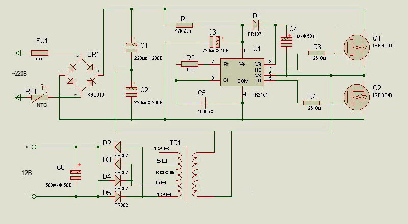
Now two types of power supplies are used: transformer and pulse. The former, using a step-down transformer, convert alternating current 220 volts 50 hertz at the required voltage. Then it through diode bridge rectified, and capacitors and transistors convert it to direct current.
The second, with the help of high-voltage diodes, 220 volt variables are first rectified, passed through a filter and converted to impulse current frequency (30-200) thousand hertz. After that, the high-frequency voltage is supplied to the transformer, and with secondary windings the required potential is released. Further transformation goes, as in a transformer power supply.
Switching current sources are widely used due to their smaller dimensions with the same power.
Transformers are needed for the safety of people and the protection of batteries from high voltage.
Current measurement
Having a general idea of the operation of the current source, you can begin to check it. If we are talking about power supplies for phones, cameras and other low-power equipment with small units, then you can measure the current in them.
How to measure current strength - a question and school textbook. A multimeter or ammeter is connected to the open circuit. Pay attention to the limit value of the scale. If the multimeter allows you to measure a maximum of 10 A, then you can check a block designed for a maximum of such a current, and no more. Our current will be constant, since it has already passed through the block.
To connect the power supply, you must either cut one of the wires or disassemble the case. The circuit must be closed to the tester. Measurements are carried out quickly, within 2 seconds, so that the contacts do not have time to get very hot.
Preparation for voltage measurement
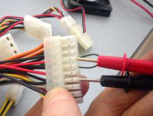
In some cases, check the voltage. Let's take a computer power supply as an example. Remove the side cover of the system box. Then disconnect all cables going to the power source.
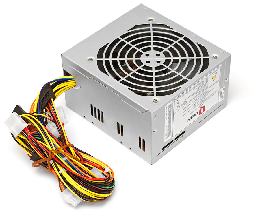
Harnesses are assembled from conductors different color, each of them corresponds to a certain voltage. Contacts with black wires correspond to common (ground). The yellow conductor supplies +12 volts, red +5 volts, orange +3.3 volts. Blue corresponds to -12 V, white -5 V, purple + 5VSB (standby power), gray PW-OK (Power good), green PS-ON. With the switch on, the PS-ON and PW-OK contacts should have +5 V.
The purple wire is live as long as the power switch on the back of the computer is turned on and plugged in. This allows you to remotely start your computer.
White is rarely used, intended for expansion cards installed in the ISA slot.
The blue wire is required for RS232, FireWire, and some PCI expansion cards.
Voltage measurement
Now you can proceed directly to the measurements. Checking the power with a multimeter is carried out in the following sequence.
In the twenty-pin connector, the connectors with a green and one black wire are shorted with a jumper. When they are shorted, the power supply starts up.
Turning the tester switch selects the measurement mode constant voltage, the range is set to 20 volts. The black test lead is connected to the common wire. Red checks the voltage on the remaining terminals. Readings must be within:
- for +5 V 4.75…5.25 V;
- for +12 V 11.4…12.6 V;
- for +3.3 V 3.14 ... 3.47 V;
- for -12 V -10.8…-13.2 V.
If the output voltages correspond to the norm, then the Power good terminal should have +5 volts. This signal is sent to motherboard and allows the processor to start.
In addition to the main harness, a few more additional ones with four-pin connectors come out of the computer's power supply. They are designed to supply voltage to hard and optical drives. Here, too, there is a color coding of signals. Measurements are made as on the main connector.
If the readings on the terminals are within the acceptable range, then the power supply is OK. So, the failure is on the motherboard.
Troubleshooting
In the absence of any voltage, values out of tolerance, you need to look for the reason for this in the power supply. To do this, it must be removed from the system box. On the back cover, the screws holding the power source case are unscrewed, and it is removed. Then you need to remove the protective cover of the power supply. After that, visual control is carried out, the presence of deposits, swelling of capacitors is checked. Batteries with these symptoms should be replaced. Further verification begins with the continuity of the circuit, in which there is no voltage.
The multimeter switches to the resistance measurement position. In this mode, the network cable must be disconnected from the power supply. One probe is connected to the contact of the connector with no potential, the second to the point of connection of the wire to the board and the measurement is taken. The device should show 0 ohms. This means that the conductor is intact. If the values are non-zero, then it needs to be replaced.
Checking the entire circuit
After replacing the defective elements, an alternating current is connected to the power supply and everything is measured again by the tester. If there is no signal, then its presence is checked along the entire circuit from the connector to the output stage of the transistor that produces this voltage. This can be traced by the lamellas (strips of copper on the board). If there is no voltage on the transistor, its presence is checked on the zener diode and capacitor. If it is absent there, then the state of the pulse transformer is checked. The power supply is disconnected from the network, and using a multimeter, the resistance of its windings is measured.

If there is no voltage on all contacts of the output connectors, then the test must be started from the point of connection network cable. The tester switches to 750 volt AC mode. Then the presence of 220 volts is checked at the output of the network cable, then at the input of the diode bridge. Since the output voltage will be rectified, the tester must be switched to direct current. This way you can identify the problem and then fix it. This completes the computer power supply check. Current sources in most other devices are arranged in the same way as the power supply discussed above. The difference may be in the output voltage ratings. If a person has disassembled and checked a computer current source with his own hands, then it will not be difficult for him to deal with the rest.


