Simple Ways inclusion of three-phase motors in a single-phase network
Each asynchronous three-phase motor is designed for two rated voltages
three-phase network 380 / 220 - 220/127, etc. The most common motors are 380 / 220V.
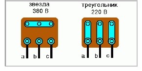
Switching the motor from one voltage to another is done by connecting the windings "to
star" - for 380 V or "triangle" - for 220 V. If the engine has a block
connection, which has 6 outputs with jumpers installed, you should pay attention to
the order in which the jumpers are installed. If the engine does not have a block and there are 6 conclusions
- usually they are collected in bundles of 3 outputs. In one bundle, the beginnings of the windings are collected, in the other the ends
(the beginning of the windings in the diagram are indicated by a dot).
In this case, “beginning” and “end” are conditional concepts, it is only important that the winding directions
coincided, i.e., on the example of a “star”, the zero point can be both the beginnings and ends of the windings, and
in the "triangle" - the windings must be connected in series, i.e. the end of one with the beginning
next. For correct connection on the "triangle" you need to determine the conclusions of each
windings, arrange them in pairs and connect in the next. scheme:
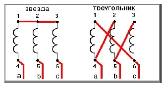
If you expand this diagram, you will see that the coils are connected in a "triangle".
If the engine has only 3 outputs, the engine should be disassembled: remove the cover from
sides of the block and in the windings find the connection of three winding wires(other
wires are connected by 2). The connection of the three wires is the zero point of the star. These 3
wires should be broken, soldered to them with lead wires and combined into one bundle. So
Thus, we already have 6 wires that need to be connected in a triangle pattern. If available
6 pins, but not bundled and there is no way to determine the beginnings and ends.
can be viewed here.
A three-phase motor can quite successfully work in single-phase network but wait from
it does not have miracles when working with capacitors. Power at best will not
more than 70% of the nominal, the starting torque is highly dependent on the starting capacity, the difficulty of selection
operating capacity under varying load. A three-phase motor in a single-phase network is
compromise, but in many cases this is the only way out.
There are formulas for calculating the capacitance of a working capacitor, but I think they are not
correct for the following reasons:
1. The calculation is made for rated power, and the engine rarely works in this
mode and underload, the engine will heat up due to the excess capacity of the working capacitor and
as a result of increased current in the winding.
2. Rated capacity capacitor indicated on its case differs from the actual +
/- 20%, which is also indicated on the capacitor. And if you measure the capacitance of a separate capacitor, it
may be twice as large or half as small. Therefore, I suggest choosing a container
to a specific motor and for a specific load, measuring the current at each point of the triangle,
trying to equalize the selection of capacity as much as possible. Since a single-phase network has
voltage is 220 V, then the motor should be connected according to the "triangle" scheme. For start
An unloaded motor can be dispensed with only a working capacitor.
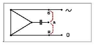
The direction of rotation of the motor depends on the connection of the capacitor (point a) to point b
or in.
Practically, the approximate capacitance of the capacitor can be determined from the next. formula: C
μf = P W / 10, where C is the capacitance of the capacitor in microfarads, P is the rated power
motor in watts. Enough to get started, and fine-tuning should be done after
engine load by a specific job. The operating voltage of the capacitor must be higher
mains voltage, but practice shows that the old Soviet paper
capacitors rated for 160V. And they are much easier to find, even in the trash.
My motor on the drill works with such capacitors, located for protection
from cotton in a grounded box from a starter, I don’t remember how many years and so far everything is intact. But to such
I do not call for an approach, just food for thought. Also, if you enable 160 and
Volt capacitors in series, we will lose twice in capacitance, but the operating voltage
320V will double and a battery of the required capacity can be assembled from pairs of such capacitors.
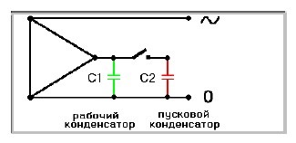
Switching on engines with revolutions above 1500 rpm, or loaded at the time of starting,
difficult. In such cases, a starting capacitor should be used, the capacity of which depends on
engine load, is selected experimentally and can approximately be equal to
working capacitor up to 1.5 - 2 times larger. In what follows, for clarity, all that
related to work will be green, everything related to start-up will be red, what to
blue inhibition.
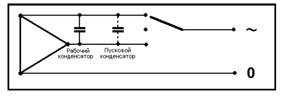
In the simplest case, you can turn on the starting capacitor using a non-fixed
buttons.
To automate the start of the engine, you can use a current relay. For engines
with a power of up to 500 W, a current relay from washing machine or a refrigerator with a small
alteration. Since the capacitor remains charged even when the engine is restarted,
a fairly strong arc occurs between the contacts and the silver contacts are welded without
disconnecting the starting capacitor after starting the engine. To prevent this from happening,
make the contact plate of the starting relay from a graphite or carbon brush (but not from copper-
graphite, because it also sticks). It is also necessary to disable the thermal protection of this relay,
if the motor power exceeds the rated power of the relay.
If the motor power is higher than 500 W, up to 1.1 kW, you can rewind the start relay winding
thicker wire and with fewer turns so that the relay
turned off immediately when the engine reached rated speed.
For a more powerful engine, you can make a homemade current relay by increasing the size
original.
Most three-phase motors up to three kW work well in
single-phase network, except for double squirrel cage motors, of ours, this is the MA series,
it is better not to mess with them, they do not work in a single-phase network.
Practical wiring diagrams
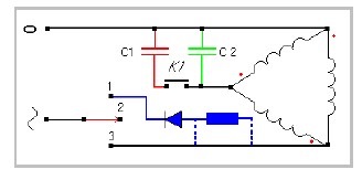
Generalizing switching circuit
C1 - starting, C2 - working, K1 - non-latching button, diode and resistor - braking system
The circuit works as follows: when the switch is moved to position 3 and
pressing the K1 button starts the engine, after releasing the button, only the working
the capacitor and the motor running on the payload. When the switch is moved to the position
1, the motor winding is supplied D.C. and the engine is braked, after stopping
it is necessary to move the switch to position 2, otherwise the motor will burn out, therefore
the switch must be special and fixed only in positions 3 and 2, and the position
1 should only be enabled when held. With motor power up to 300W and
the need for rapid braking, the quenching resistor can be omitted, with a larger
power, the resistance of the resistor is selected according to the desired braking time, but should not
be less than the motor winding resistance.
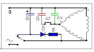
This scheme is similar to the first one, but braking here occurs due to the energy stored in
electrolytic capacitor C1 and the braking time will depend on its capacity. As in
any scheme, the start button can be replaced with a current relay. When the switch is turned on
the engine starts and the capacitor C1 is charged through VD1 and R1. R1 resistance
selected depending on the power of the diode, the capacitance of the capacitor and the operating time of the engine
before the start of braking. If the engine running time between starting and braking exceeds 1
minute, you can use the KD226G diode and a 7kΩ resistor of at least 4W. operating voltage
capacitor at least 350V For fast braking, a capacitor from
flashlights, there are many flashlights, but there is no need for them anymore. When you turn off the switch
switches to the position closing the capacitor to the motor winding and braking occurs
direct current. A conventional two-position switch is used.
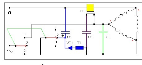
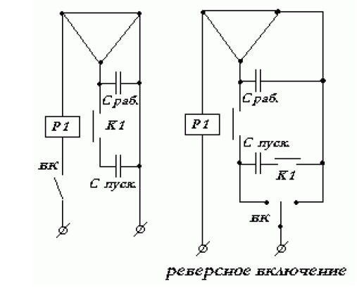
Scheme of reverse switching and braking
This scheme is a development of the previous one, here it is automatically launched using
current relay and braking by an electrolytic capacitor, as well as reverse switching.
The difference between this circuit: a dual three-position switch and a starting relay. Throwing out
this scheme, extra elements, each of which has its own color, you can assemble the scheme you need
for specific purposes. If desired, you can switch to push-button switching, for this you will need one or two automatic starters with a 220V coil.
three position switch.
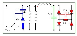
Another not quite usual automatic switching scheme.
As in other schemes, there is a braking system here, but if it is not needed, it is easy to
throw out. In this switching circuit, two windings are connected in parallel, and the third through the system
start and an auxiliary capacitor, the capacity of which is approximately half the required
when turned on by a triangle. To change the direction of rotation, you need to swap
the beginning and end of the auxiliary winding, indicated by red and green dots. launch
occurs due to the charging of the capacitor C3 and the duration of the start depends on the capacitance
capacitor, and the capacitance must be large enough so that the engine has time to reach
nominal speed. The capacity can be taken with a margin, since after charging the capacitor does not
has a significant effect on engine performance. Resistor R2 is needed to discharge the capacitor
and thus preparing it for the next start, 30 kOhm 2W will do. Diodes D245 - 248
suitable for any engine. For engines of lower power, respectively, will decrease and
the power of the diodes, and the capacitance of the capacitor. Although it is difficult to reverse the inclusion
according to this scheme, but if desired, this can also be done. Requires complex switch or triggers
automata.
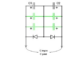
The use of electrolytic capacitors as starting and working
The cost of non-polar capacitors is quite high, and not everywhere they can be found.
Therefore, if they are not available, you can use electrolytic capacitors connected according to the scheme not
much more difficult. Their capacity is large enough with a small volume, they are not in short supply and do not
roads. But new factors must be taken into account. The operating voltage must be at least
350 volts, they can only be switched on in pairs, as indicated in the diagram in black, and in this
case, the capacitance is halved. And if the motor needs 100 microfarads to run, then the capacitors
C1 and C2 should be 200uF each.
Electrolytic capacitors have a large capacitance tolerance, so it is better to collect
capacitor bank (marked in green), it will be easier to select the actual capacity
necessary for the engine, and in addition, electrolytes have very thin leads, and the current with a large capacity
can reach significant values and the conclusions can heat up, and in case of an internal break, cause
capacitor explosion. Therefore, the entire capacitor bank must be in a closed box,
especially during experiments. Diodes must be with a margin of voltage and current,
necessary for work. Up to 2 kW, D 245 - 248 are quite suitable. When the diode breaks down, it burns out (
explodes) capacitor. The explosion, of course, is said loudly, the plastic box will completely protect against
scattering of parts of the capacitor and from the shiny serpentine too. Well, horror stories are told,
now a little about the design.
As can be seen from the diagram, the minuses of all capacitors are connected together and, therefore,
capacitors of the old design with a minus on the case can simply be tightly rewound
tape and place in an appropriately sized plastic box. Diodes need
place on an insulating plate and, at high power, put them on small
radiators, and if the power is not high and the diodes do not heat up, then they can be placed in the same box.
Electrolytic capacitors included in this scheme work quite successfully as
launchers and workers.
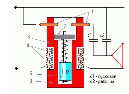
Inclusion starting capacitor using a current relay.
It is known from theory that the starting current is several times higher than the rated current of the working
motor, so the inclusion of a starting capacitor when a three-phase motor is turned on in
a single-phase network can be carried out automatically - using a current relay.
For engines up to 0.5 kW, a starting relay from a refrigerator, washing machine is suitable
type RP-1, with a slight alteration. Moving contacts should be replaced with graphite or
carbon plate, machined from the brush of the collector motor, according to the size of the original. T. to.
when turned on again, the current of the charged capacitor produces a large spark at the contacts, and
standard contacts are welded together. When using graphite, this phenomenon is not
observed. (In addition, the thermal relay should be turned off).
For engines up to 1 kW, you can rewind RP-1 with a wire Ф1.2mm until the coil is filled
40-45 turns.
For more powerful engines, a current relay should be made by analogy with RP-1, larger
size.
The winding wire of the relay must match rated current engine, based on
5A / 1mm?
The number of turns should be selected experimentally, for a clear switching on of the relay when
startup and shutdown after startup. It is better to wind more turns and rewind until you reach
clear shutdown after start-up.
single-phase network
Alteration of the engine is to change the armature of the engine.
1- copper rods made of wire Ф2-2.5mm are pressed into slightly smaller holes
or on the glue of the wires, a 2-disk of graphite brush F is simply soldered to them, 1.5 mm less than F
body, thickness 1.5-2mm 3- body 4- winding 5- armature
The relay housing can be made of textolite, getinax, ebonite, etc. Rod -
aluminum wire, magnetic anchor - mild steel cylinder machined into shape
glass.
To make the construction clearer homemade relay, you can disassemble the relay RP-1 and
make an analogue, proportionally increasing the details. Approximate case size Ф30mm h 60mm.
The armature and the contact disk must move freely along the rod. The spring must not be
too strong.
Turning on and reversing a three-phase asynchronous motor (380/220) in
single-phase network with one switch
Many reversal schemes presented on the Internet are unreasonably complicated and
have an unreasonably large number of switches.
Offered simple circuit switching on and reversing with one switch.
Almost any switch with 3 fixed positions will do.
corresponding to the engine power.
If necessary - this scheme facilitates the automation of switching on - off and
engine reversal.
If necessary, a starting capacitor (switching on a loaded or
high-speed motor), it can be connected using a start button or a current relay.
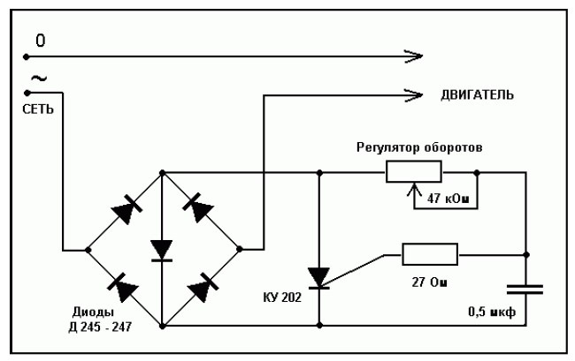
Changing the speed of a three-phase asynchronous motor (380/220) included in
single-phase network
In order not to use an expensive and complex collector motor in mechanisms requiring
changes in engine speed, you can get by with asynchronous three-phase motor by entering into
phase wire rheostat or the simplest power regulator.
Based on the model of the anchor installed in the engine, a “massive anchor” is made from
soft magnetic mild steel or gray cast iron (SC). (Cast iron works best.)
old anchor, you can press out the shaft and put a massive anchor on it.
I'm going to use a circuit using a current relay to turn off the start capacitor.
For an asynchronous motor, we have already mastered it, so it remains only to connect the developed nodes into one circuit diagram. We put the conclusions of the control circuit on phases C1 and C3, and the electric motor to the output of the thermal relay, that's the whole circuit for connecting an asynchronous motor through a starter.
Look, if you remove the blocking of the start buttons with contacts KM1.1 and KM2.1, when the buttons are released, the starters will turn off. Somewhere this may be inconvenient, but in it is considered mandatory.
There is a small flaw in this scheme: I described three-phase connection thermal relay, and in Fig. 3, only two of its phases are involved. There is nothing terrible, you can make such a connection of a thermal relay, but it turned out to be a connection diagram for an asynchronous motor using a two-phase thermal relay.
engine start star triangle
Ever notice how? So when starting a powerful electric motor, the voltage in the network drops due to the large starting current. In order to reduce the starting current, they came up with a phased start of the star-delta engine (the triangle is designed for 380V). Each stator phase has its own winding, which has a beginning and an end, and they are brought to the terminal box. 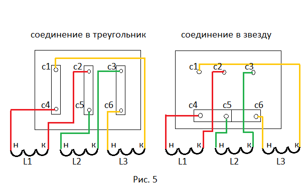
The value of the beginning and end is important: for example, when connecting the windings into a triangle, the end of the first winding is connected to the beginning of the second, the end of the second to the beginning of the third, and the end of the third to the beginning of the first. Otherwise, the engine will not pull. In the box, switching from a star to a triangle is carried out by jumpers c4-c5-c6 to c1-c4, c2-c5, c3-c6. But at startup, do not open the box and rearrange the jumpers, for this they came up with a start-up using two contactors KM2 and KM3, replacing these plates. 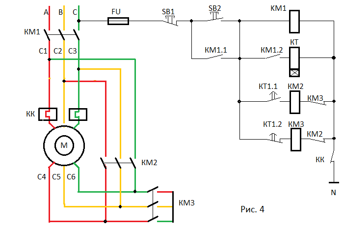
How to do it? First of all, remove the jumpers, then connect all the winding leads to the contactors KM1, KM2 and KM3 according to the diagram (Fig. 4).
How does such a scheme work? When the start button SB2 is pressed, the main contactor KM1 is turned on, which starts the time relay KT with its contact KM1.2 and blocks the start button with the contact KM1.1. At the same time, the KM3 contactor is turned on, connecting the stator windings into a star, and opens the KM2 coil circuit with its KM3 contact to prevent it from being accidentally turned on. Star launch completed.
After acceleration, the contact of the time relay KT1.2 is turned off, the coil of the contactor KM3 is de-energized, the contact KM3 returns to its original position. At this time, the contact of the time relay KT1.1 closes, turns on the coil of the KM2 contactor, connecting the windings into a triangle and insuring the KM3 coil from turning on, opening its contact KM2. Now the engine has started to work on the triangle we need.
It is very important to adjust the timing relay so that the moment of its operation corresponds to the full acceleration on the star.
Note: the control circuit is connected to 220V, that is, to phase and to "zero" N, the motor connection circuit through a starter in lifting mechanisms should only work at 380V, 220V is allowed to be connected through a 380/220V transformer.
The problem of large inrush current is effectively solved by connecting
Three-phase motors
In the "General" section, we will consider ways to start three-phase asynchronous motors with a squirrel-cage rotor. Currently in use various ways starting asynchronous motors. When starting the engine, the basic requirements must be met. The launch should take place without the use of complex starting devices. The starting torque must be large enough and the starting currents as low as possible. Modern electric motors are energy efficient motors and have higher starting currents, which requires more attention to their starting methods. When the supply voltage is applied to the motor, a current surge occurs, which is called the starting current.
The starting current usually exceeds the rated current by 5-7 times, but its effect is short-lived. After the motor has reached its nominal speed, the current drops to a minimum. In accordance with local codes and regulations, to reduce inrush currents, and are used different ways starting asynchronous motors with a squirrel-cage rotor. At the same time, it is necessary to pay attention to voltage stabilization. mains supply. Speaking of starting methods that reduce the starting current, it should be noted that the starting period should not be too long. Too long start-up periods can cause the windings to overheat.
direct launch
The simplest and most commonly used way to start induction motors is direct starting. Direct start means that the motor is started by direct connection to the mains voltage. Direct start is used for stable power supply of a motor that is rigidly connected to the drive, such as a pump. (Fig. 1) shows a diagram of the direct start of an asynchronous motor.
Motor connection in electrical network occurs with the help of a contactor (starter). An overload relay is necessary to protect the motor during operation from overcurrent. Motors of small and medium power are usually designed so that when the stator windings are directly connected to the mains supply, the inrush currents that occur during start-up do not create excessive electrodynamic forces and temperature rises on the motor, in terms of mechanical and thermal strength. The transient process at the moment of starting is characterized by a very fast decay of the free current, which makes it possible to neglect this current and take into account only the steady value of the transient current. The graph (Fig. 1) shows the characteristic of the starting current during direct start of an asynchronous motor with a squirrel-cage rotor.
Direct-on-line starting is the simplest, cheapest, and most commonly used starting method. With this start, there is the smallest temperature rise in the motor windings during start-up compared to all other starting methods. If there are no hard current limits, then this starting method is the most preferable. AT different countries different rules and regulations apply to limit the maximum starting current. In such cases, other launch methods must be used.
For small motors, the starting torque will be between 150% and 300% of rated torque, and the starting current will be from 300% to 700% of nominal value or even higher.
Star-delta starting is used for three-phase induction motors and is used to reduce the starting current. It should be noted that starting by switching "star - delta" is possible only in those motors in which the beginnings and ends of all three windings are removed. The star-delta starter console consists of the following components, three contactors (starters), an overcurrent relay and a time relay that controls the switching of starters. In order to be able to use this starting method, the delta-connected stator windings of the electric motor must be designed to operate in the nominal mode. Typically motors are rated at 400 V when connected in delta (∆) or 690 V when connected in star (Y). This unified connection scheme can also be used to start the motor at a lower voltage. The star-delta start scheme is shown in (Fig. 2)
start star triangle
At the moment of start-up, the power supply to the stator windings is connected according to the “star” (Y) scheme. Contactors K1 and K3 are closed. After a certain period of time, depending on the motor power and acceleration time, it switches to delta start mode (∆). In this case, the contacts of the starter K3 open, and the contacts of the starter K2 close. Controls switching of contacts of starters K3 and K2 of the time relay. The relay sets the time during which the engine accelerates. In the star-delta start mode, the voltage applied to the phases of the stator winding decreases by the root of three times, which leads to a decrease in phase currents also by the root of three times, and linear currents by 3 times. The star-delta connection gives a lower starting current of only one third of the direct start current. Star-delta starting is particularly well suited for inertial systems where the load is "picked up" after the motor has run up.
The star-delta start also reduces the starting torque by about a third. This method can only be used for induction motors that have a delta connection to the supply voltage. If star-delta switching occurs with insufficient acceleration, this can cause overcurrent, which reaches almost the same value as the current during direct start. During the time of switching from the "star" to the "delta" mode, the motor very quickly loses its rotational speed, and a powerful current pulse is needed to restore it. The current surge can become even greater, since the motor remains without mains voltage for the duration of the changeover.
This method starting is carried out using an autotransformer connected in series with the electric motor during starting. The autotransformer reduces the voltage supplied to the motor (approximately 50-80% of the rated voltage) to start at a lower voltage. Depending on the set parameters, the voltage is reduced in one or two stages. Reducing the voltage applied to the motor at the same time will lead to a decrease in starting current and rotating starting torque. If power is not supplied to the electric motor at a certain point in time, it will not lose rotational speed, as is the case with star-delta start. Switching time from undervoltage to full voltage can be corrected. (Fig. 3) shows the characteristic of the starting current when starting an asynchronous motor with a squirrel-cage rotor using an autotransformer.
Starting via current autotransformer
In addition to reducing the starting torque, the method of starting through an autotransformer has a drawback. As soon as the electric motor starts running, it switches to mains voltage, which causes a current surge. The torque depends on the voltage applied to the motor. The value of the starting torque is proportional to the square of the voltage.
Smooth start
The soft starter uses the same IGBT transistors as the frequency converters. These transistors, through the control circuits, lower the initial voltage supplied to the electric motor, which leads to a decrease in the starting torque in the electric motor. During the starting process, "soft start" gradually increases the voltage of the motor, which allows the motor to accelerate to rated speed without generating large torque and current peaks.(Fig. 4) shows the characteristic of the starting current when starting an asynchronous motor with a squirrel-cage rotor using a soft starter. Soft start can also be used to control the braking of the motor. A "soft start" device is cheaper than a frequency converter. The use of a “soft starter” for asynchronous motors significantly increases the service life of the electric motor, and with it the pump located on the shaft of this motor.
Soft start has the same problems as frequency converters: they create interference (interference) in the power supply system. This method also provides reduced voltage to the motor during start-up. With soft start, the motor starts at a reduced voltage, which then increases to the mains voltage. The voltage in the soft starter decreases due to the phase shift. This starting method does not cause current surges. Start time and starting current can be set.
Starting a motor with a frequency converter
Frequency converters are still expensive devices, and like soft starters, they create additional interference in the power supply network.
Conclusion
The goal of any motor starting method is to match the torque characteristics of the motor with the characteristics of the mechanical load, while ensuring that peak currents do not exceed allowable values. There are various ways to start induction motors, each with its own pros and cons. And in conclusion, a small table is given, which briefly lists the advantages and disadvantages of the most common ways to start asynchronous motors.
Table 1
|
Launch methods |
Advantages |
Flaws |
|
direct launch |
Simple and economical.Safe StartBiggest starting torque | High starting current |
|
Star-delta launch |
Reducing the starting current by three times. | Current surges during star-delta switching.Reduced starting torque. |
|
Starting via autotransformer |
Reducing the starting current by U 2. | Current surges during the transition from reduced voltage to rated voltage.Reduced starting torque. |
|
Soft start |
There are no current surges. Slight water hammer when starting the pump.Reducing the starting current by the required value, usually 2-3 times. | Reduced starting torque. |
|
Starting with a frequency converter |
There are no current surges.Slight water hammer when starting the pump.Reducing the starting current, usually to the nominal.The supply voltage to the motor can be applied continuously. | Reduced starting torque.High price. |
Thank you for your attention.


