1 Real and ideal sources of email. energy. equivalent schemes. Any source electrical energy converts other types of energy (mechanical, light, chemical, etc.) into electrical energy. The current in the source of electrical energy is directed from negative to positive due to external forces due to the type of energy that the source converts into electrical energy. The real source of electrical energy in the analysis of electrical circuits can be represented either in the form voltage source or as a power source. Below is an example of an ordinary battery.
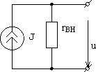
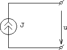
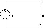
Ways of presenting a real source of electrical energy differ from each other by equivalent circuits (design diagrams). On fig. 15 the real source is represented (replaced) by a voltage source circuit, and in fig. 16, the real source is represented (replaced) by the current source circuit.
|
|
|
||

|
|
|||
|
| |||
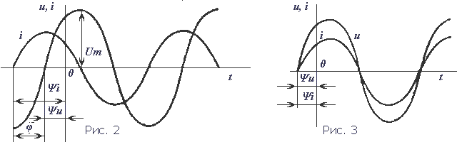
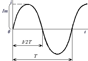
Period(T) - time (s) during which the variable makes a complete oscillation. Frequency is the number of cycles per second. The unit of frequency is Hertz (abbreviated Hz), 1 Hz is equal to one oscillation per second. Period and frequency are related T=1/f. Changing over time, the sinusoidal value (voltage, current, EMF) takes on various meanings. The value of a quantity at a given point in time is called instantaneous. Amplitude - highest value sinusoidal value. Amplitudes of current, voltage and EMF are indicated in capital letters with an index: I m, U m, E m, and their instantaneous values - in lower case letters i, u, e. The instantaneous value of a sinusoidal quantity, for example current, is determined by the formula i = I m sin(ωt + ψ), where ωt + ψ is the phase-angle that determines the value of the sinusoidal quantity at a given time; ψ is the initial phase, i.e., the angle that determines the value of the quantity at the initial moment of time. Sinusoidal quantities that have the same frequency but different initial phases are called phase-shifted.
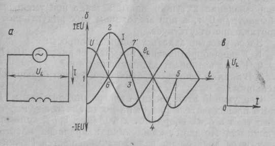
3 On fig. 2 shows graphs of sinusoidal quantities (current, voltage) shifted in phase. When the initial phases of the two quantities are equal to ψ i = ψ u , then the difference is ψ i − ψ u = 0 and, therefore, there is no phase shift φ = 0 (Fig. 3). The effectiveness of the mechanical and thermal action of alternating current is estimated by its effective value. The effective value of the alternating current is equal to this value direct current, which, in a time equal to one period of alternating current, will release in the same resistance the same amount of heat as alternating current. The current value is indicated in capital letters without an index: I, U, E. Rice. 2 Graphs of sinusoidal current and voltage shifted in phase. Rice. 3 Graphs of sinusoidal current and voltage, coinciding in phase
For sinusoidal values, the effective and amplitude values are related by the relations:
I=IM /√2; U=U M /√2; E=E M √2. The effective values of current and voltage are measured by ammeters and voltmeters of alternating current, and the average value of power is measured by wattmeters.
4 .Valid (effective) valuestrengthalternating current called the amount of direct current, the action of which will produce the same work (thermal or electrodynamic effect) as the considered alternating current during one period. More commonly used in modern literature mathematical definition of this value is the rms value of the alternating current. In other words, the effective value of the current can be determined by the formula:
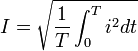 .
.
For harmonic current oscillations
![]()
5Inductive reactance formula:
where L is the inductance.
Capacitance formula:
![]()
where C is the capacitance.
We propose to consider an alternating current circuit, which includes one active resistance, and draw it in notebooks. After checking the drawing, I tell you that in electrical circuit(Fig. 1, a) under the action of an alternating voltage, an alternating current flows, the change of which depends on the change in voltage. If the voltage increases, the current in the circuit increases, and when the voltage is zero, there is no current in the circuit. A change in its direction will also coincide with a change in the direction of the voltage
(Fig. 1, c).
![]()
Fig 1. AC circuit with active resistance: a - diagram; b - vector diagram; c - wave diagram
I graphically depict current and voltage sinusoids on the board that are in phase, explaining that although the period and frequency of oscillations, as well as the maximum and effective values, can be determined from the sinusoid, nevertheless it is quite difficult to build a sinusoid. A simpler way to represent current and voltage values is vector. For this stress vector (to scale) should be plotted to the right from an arbitrarily chosen point. The teacher invites students to postpone the current vector on their own, recalling that the voltage and current are in phase. After constructing a vector diagram (Fig. 1, b), it should be shown that the angle between the voltage and current vectors is equal to zero, i.e. ? = 0. The current strength in such a circuit will be determined by Ohm's law: Question 2. AC circuit with inductive resistance Consider an AC circuit (Fig. 2, a), which includes an inductive resistance. Such a resistance is a coil with a small number of turns of large wire, in which the active resistance is considered to be 0.
Rice. 2. AC circuit with inductive resistance
Around the turns of the coil, during the passage of current, an alternating magnetic field will be created, inducting in the turns of the emf of self-induction. According to Lenz's rule, the ede of induction always counteracts the cause that causes it. And since this self-induction is caused by changes in the alternating current, it prevents its passage. The resistance caused by this self-induction is called inductive and is denoted by the letter x L. The inductive resistance of the coil depends on the rate of change of the current in the coil and its inductance L: where X L is the inductive resistance, Ohm; is the angular frequency of the alternating current, rad/s; L is the inductance of the coil, G.
Angular frequency == ,
Consequently, .
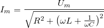
Capacitance in an alternating current circuit. Before starting the explanation, it should be recalled that there are a number of cases when in electrical circuits, in addition to active and inductive resistances, there is also capacitive resistance. A device designed to store electrical charges is called a capacitor. The simplest capacitor is two wires separated by a layer of insulation. That's why stranded wires, cables, motor windings, etc. have capacitive resistance. Explanation followed by showing the capacitor various types and capacitances with their connection to the electrical circuit. I propose to consider the case when one capacitive resistance predominates in the electrical circuit, and active and inductive ones can be neglected because of their small values (Fig. 6, a). If the capacitor is connected to a DC circuit, then no current will flow through the circuit, since there is a dielectric between the capacitor plates. If the capacitance is connected to an alternating current circuit, then a current / will flow through the circuit, caused by the recharging of the capacitor. Recharging occurs because the alternating voltage changes its direction, and therefore, if we connect an ammeter in this circuit, it will show the charging and discharging current of the capacitor. No current passes through the capacitor. The strength of the current passing in a circuit with capacitance depends on the capacitance of the capacitor Xc and is determined by Ohm's law 
where U is the voltage of the emf source, V; Xs - capacitive resistance, Ohm; / - current strength, A.

Rice. 3. AC circuit with capacitance
Capacitance, in turn, is determined by the formula 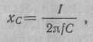
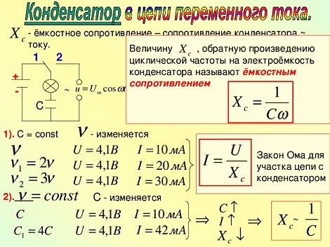
where C is the capacitance of the capacitor, F. I suggest that students build a vector diagram of current and voltage in a circuit with capacitance. I remind you that when studying processes in an electrical circuit with capacitive resistance, it was found that the current leads the voltage by an angle φ = 90 °. This phase shift of current and voltage should be shown on the wave diagram. I graphically depict a voltage sinusoid on the board (Fig. 3, b) and instruct students to independently draw a current sinusoid on the drawing, leading the voltage by an angle of 90 °
DEFINITION
Capacitor, in the simplest case consists of two metal conductors(plates), which are separated by a dielectric layer. Each of the capacitor plates has its own output and can be connected to an electrical circuit.
A capacitor is characterized by a number of parameters (capacitance, operating voltage, etc.), one of these characteristics is resistance. The capacitor practically does not pass direct electric current. That is capacitor resistance is infinitely large for direct current, but this is the ideal case. Very little current can flow through a real dielectric. This current is called leakage current. Leakage current is an indicator of the quality of the dielectric, which is used in the manufacture of a capacitor. In modern capacitors, the leakage current is a few fractions of a microampere. The resistance of the capacitor in this case can be calculated using Ohm's law for the circuit section, knowing the voltage to which the capacitor is charged and the leakage current. But usually, when solving educational problems, the resistance of a capacitor to direct current is considered infinitely large.
Capacitor AC resistance
When a capacitor is connected to an AC circuit, current flows freely through the capacitor. This is explained very simply: there is a process of constant charging and discharging of the capacitor. In this case, they say that the capacitance of the capacitor is present in the circuit, in addition to the active resistance.
And so, the capacitor, which is included in the alternating current circuit, behaves like a resistance, that is, it affects the strength of the current flowing in the circuit. We denote the value of capacitive resistance as , its value is related to the frequency of the current and is determined by the formula:
![]()
where is the frequency of the alternating current; - angular frequency of the current; C is the capacitance of the capacitor.
If the capacitor is connected to an alternating current circuit, then no power is expended in it, because the phase of the current is shifted with respect to the voltage by. If we consider one period of current oscillation in the circuit (T), then the following happens: when the capacitor is charged (this is), energy is stored in the capacitor field; in the next time interval (), the capacitor is discharged and gives off energy to the circuit. Therefore, capacitive resistance is called reactive (wattless).
It should be noted that in every real capacitor, real power (power loss) is still wasted when an alternating current flows through it. This is because changes occur in the state of the dielectric of the capacitor. In addition, there is some leakage in the insulation of the capacitor plates, so a small active resistance appears, which, as it were, is connected in parallel with the capacitor.
Examples of problem solving
EXAMPLE 1
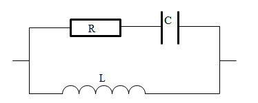
| Exercise | The oscillatory circuit has a resistance (R), an inductor (L) and a capacitance C (Fig. 1). An external voltage is connected to it, the amplitude of which is , and the frequency is . What is the amplitude of the current in the circuit? |
| Solution | The resistance of the circuit in Fig. 1 is the sum of the active resistance R, the capacitance of the capacitor and the resistance of the inductor. The total resistance of the circuit (Z), which contains the above elements, is found as: Ohm's law for our section of the circuit can be written as: Let us express the desired amplitude of the current strength from (1.2), substitute instead of Z right side formulas (1.1), we have:
|
| Answer |
One of the main devices in electronics and electrical engineering is a capacitor. After the electrical circuit is closed, charging begins, after which it immediately becomes a source of current and voltage, an electromotive force arises in it - EMF. One of the main properties of a capacitor is very accurately reflected in the capacitance formula. This phenomenon occurs as a result of the counteraction of the EMF directed against the current source used for charging. The current source can overcome the capacitance only by spending a significant amount of its own energy, which becomes the energy electric field capacitor.
When the device is discharged, all this energy is returned back to the circuit, turning into energy. electric current. Therefore, capacitive resistance can be attributed to reactive, not causing irreversible energy losses. The capacitor is charged up to the level of voltage that is given by the power source.
Capacitor capacitance
Capacitors are among the most common elements used in various electronic circuits. They are divided into types with characteristic features, parameters and individual properties. The simplest capacitor consists of two metal plates - electrodes, separated by a dielectric layer. Each of them has its own output through which the connection to the electrical circuit is made.
There are qualities that are unique to capacitors. For example, they do not pass direct current through themselves at all, although they are charged from it. After the capacitance is fully charged, the current flow stops completely, and the internal resistance of the device takes on an infinitely high value.
In a completely different way, the capacitor is affected, completely freely flowing through the capacitance. This state is explained by the constant processes of charging and discharging the element. In this case, not only the active resistance of the conductors acts, but also the capacitance of the capacitor itself, which arises precisely as a result of its constant charging and discharging.
The electrical parameters and properties of capacitors may vary, depending on various factors. First of all, they depend on the size and shape of the product, as well as on the type of dielectric. AT different types devices can serve as paper, air, plastic, glass, mica, ceramics and other materials. Electrolytic capacitors use aluminum electrolyte and tantalum electrolyte, which provides them with increased capacitance.

The names of other elements are determined by the materials of ordinary dielectrics. Therefore, they belong to the category of paper, ceramic, glass, etc. Each of them, in accordance with the characteristics and features, is used in specific electronic circuits, with different parameters of the electric current.
For this reason, the application ceramic capacitors necessary in those circuits where high-frequency noise filtering is required. Electrolytic devices, on the contrary, filter interference when low frequencies. If you connect both types of capacitors in parallel, you get a universal filter that is widely used in all circuits. Despite the fact that their capacitance is a fixed value, there are devices with a variable capacitance, which is achieved by adjustments by changing the mutual overlap of the plates. A typical example is the trim capacitors used in the adjustment of electronic equipment.
Capacitance in the AC circuit
When a capacitor is connected to a DC circuit, a charging current flow will be observed for a short period of time. At the end of charging, when the voltage of the capacitor corresponds to the voltage of the current source, the short-term current flow in the circuit will stop. Thus, completely at direct current there will be a kind of open circuit or resistance with an infinitely large value. With alternating current, the capacitor will behave completely differently. Its charging in such a circuit will be carried out alternately in different directions. The flow of alternating current in the circuit is not interrupted at this time.
A more detailed consideration of this process indicates a zero voltage value in the capacitor at the moment it is turned on. After joining him AC voltage the network will start charging. At this time, the mains voltage will increase during the first quarter of the period. As charges accumulate on the plates, the voltage of the capacitor itself increases. After the mains voltage reaches its maximum at the end of the first quarter of the period, charging stops and the current in the circuit becomes equal to zero.
There is a formula for determining the current in a capacitor circuit: I = ∆q/∆t, where q is the amount of electricity flowing through the circuit during a period of time t. In accordance with the laws of electrostatics, the amount of electricity in the device will be: q \u003d C x Uc \u003d C x U. In this formula, C will be the capacitance of the capacitor, U - the mains voltage, Uc - the voltage on the element plates. In the final form, the formula for the current in the circuit will look like this: i = C x (∆Uc/∆t) = C x (∆U/∆t).
At the onset of the second quarter of the period, the mains voltage will decrease and the capacitor will begin to discharge. The current in the circuit will change its direction and will flow in the opposite direction. In the next half of the period, the direction of the mains voltage will change, the element will be recharged, and then it will start to discharge again. The current present in the capacitor circuit will lead the voltage on the plates by 90 degrees in phase.
It has been established that changes in the capacitor current occur at a rate that is proportional to the angular frequency ω. Therefore, in accordance with the already known formula for the current in the circuit i \u003d C x (∆U / ∆t), it similarly turns out that the effective value of the current will also be a proportion between the rate of change of voltage and the angular frequency ω: I = 2π x f x C x U .
Further, it is quite easy to set the value of the capacitance or reactance of the capacitance: xc = 1/2π x f x C = 1/ ω x C. This parameter is calculated when the capacitive capacitance is included in the AC circuit. Therefore, in accordance with Ohm's law in an alternating current circuit with a capacitor on, the current strength will be as follows: I = U / xc, and the voltage on the plates will be: Uc = Ic x xc.
The part of the mains voltage that falls on the capacitor is called the capacitive voltage drop. It is also known as the reactive component of the voltage, denoted by the symbol Uc. The value of the capacitance xs, as well as the value of the inductive reactance xi is directly related to the frequency of the alternating current.
Let's close the chain. The circuit will charge the capacitor. This means that part of the electrons from the left side of the capacitor will go into the wire, and the same number of electrons will go from the wire to the right side of the capacitor. Both plates will be charged with opposite charges of the same magnitude.
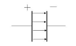
Between the plates in the dielectric will be electric field.
Now let's break the chain. The capacitor will remain charged. We will shorten its lining with a piece of wire. The capacitor will instantly discharge. This means that an excess of electrons will go into the wire from the right plate, and a lack of electrons will enter the wire to the left plate. On both plates of electrons will be the same, the capacitor will be discharged.
What voltage is the capacitor charged to?
It charges up to the voltage that is applied to it from the power source.
Capacitor resistance.
Let's close the chain. The capacitor began to charge and immediately became a source of current, voltage, E.D.S.. The figure shows that the E.D.S. of the capacitor is directed against the current source charging it.
Opposition electromotive force of a charged capacitor the charge of this capacitor is called capacitive reactance.
All the energy expended by the current source to overcome the capacitive
resistance is converted into the energy of the electric field of the capacitor.
When the capacitor is discharged all the energy of the electric field
back into the circuit in the form of electrical energy. So
Thus, the capacitance is reactive, i.e. without causing irreversible loss of energy.
Why does direct current not pass through a capacitor, while alternating current does?
 |
 |
 |
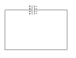
Turn on the DC circuit. The lamp flashes on and off, why? Because the capacitor charge current passed in the circuit. As soon as the capacitor is charged to the battery voltage, the current in the circuit will stop.
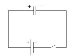
Now let's close the AC circuit. In the first quarter of the period, the voltage on the generator increases from 0 to a maximum. The circuit is charging a capacitor. In the second quarter of the period, the voltage on the generator decreases to zero. The capacitor is discharged through the generator. After that, the capacitor is charged and discharged again. Thus, in the circuit there are currents of charge and discharge of the capacitor. The lamp will be on constantly.
In a circuit with a capacitor, current flows in the entire closed circuit, including in the dielectric of the capacitor. In a charging capacitor, an electric field is formed that polarizes the dielectric. Polarization is the rotation of electrons in atoms in elongated orbits.
The simultaneous polarization of a huge number of atoms forms a current called displacement current. Thus, the current flows in the wires and in the dielectric, and the same value.
capacitor is determined by the formula
On the active resistance, the voltage U act and the current I are in phase. On the capacitance, the voltage U c lags behind the current I by 90 0 . The resulting voltage applied by the generator to the capacitor is determined by the parallelogram rule. This resulting voltage lags behind the current I by some angle φ, which is always less than 90 0 .
Determination of the resulting capacitor resistance
The resulting resistance of a capacitor cannot be found by summing up the values of its active and capacitive resistances. This is done according to the formula


