In a number of countries to asynchronous machines collector machines are also included. Another name for asynchronous machines is induction due to the fact that the current in the rotor winding is induced by the rotating field of the stator. Asynchronous machines today make up the majority of electrical machines. They are mainly used as electric motors and are the main converters. electrical energy into mechanical.
Advantages:
- Ease of manufacture.
- No mechanical contact with the static part of the machine.
Flaws:
- Small Starting torque.
- Significant starting current.
Story
The priority in creating an induction motor belongs to Nikola Tesla, who in Budapest in the spring of 1882 solved the problem of creating a rotating magnetic field with fixed multi-phase winding alternating current, and in 1884 in Strasbourg he demonstrated a working model of his engine. A contribution to the development of asynchronous motors was made by Galileo Ferraris, who in 1885 in Italy built a model of a 3 W induction motor. In 1888, Ferraris published his research in an article for the Royal Academy of Sciences in Turin (in the same year, Tesla received US Patent 381,968 dated 05/01/1888 ( U.S. Patent 0 381 968 | application for invention No. 252132 dated 10/12/1887), which outlined theoretical basis asynchronous motor. The merit of Ferraris is that having made an erroneous conclusion about a small efficiency. asynchronous motor and the inexpediency of using alternating current systems, he drew the attention of many engineers to the problem of improving asynchronous machines. An article by Galileo Ferraris published in the journal Atti di Turino was reprinted by an English journal and was read in July 1888 by Mikhail Osipovich Dolivo-Dobrovolsky, a graduate of the Darmstadt Higher Technical School, a native of Russia. Already in 1889, Dolivo-Dobrovolsky received a patent for a three-phase asynchronous motor with a squirrel-cage rotor, and in 1890 - patents in England No. 20425 and Germany No. 75361 for a three-phase asynchronous motor with a phase rotor. These inventions opened the era of mass industrial application of electrical machines. At present, the asynchronous motor is the most common electric motor.
Design
An asynchronous machine has a stator and rotor separated by an air gap. Its active parts are windings and a magnetic circuit (core); all other parts are structural, providing the necessary strength, rigidity, cooling, the possibility of rotation, etc.
The stator winding is a three-phase (in general case- multi-phase) winding, the conductors of which are evenly distributed around the circumference of the stator and are phase-by-phase laid in grooves with an angular distance of 120 el.deg. The phases of the stator winding are connected by standard schemes"triangle" or "star" and connect to the network three-phase current. The stator magnetic circuit is remagnetized in the process of changing the current in the stator winding, so it is recruited from electrical steel plates to ensure minimal magnetic losses. The main method of assembling the magnetic circuit into a package is blending.
According to the design of the rotor, asynchronous machines are divided into two main types: with short-circuited rotor and phase rotor. Both types have the same stator design and differ only in the design of the rotor winding. The rotor magnetic circuit is made similarly to the stator magnetic circuit - from electrical steel plates.
squirrel-cage rotor
Rotor of asynchronous squirrel-cage machine
The short-circuited rotor winding, often called the "squirrel cage" due to the external similarity of the design, consists of copper or aluminum rods, short-circuited at the ends with two rings. The rods of this winding are inserted into the grooves of the rotor core. Rotor and stator cores have a gear structure. In machines of small and medium power, the winding is usually made by pouring molten aluminum alloy into the grooves of the rotor core. Together with the "squirrel cage" rods, short-circuiting rings and end blades are cast, which ventilate the machine. In high power machines, the "squirrel cage" is made of copper rods, the ends of which are connected to short-circuit rings by welding.
Often, the grooves of the rotor or stator are made beveled to reduce higher harmonic EMF caused by magnetic flux ripples due to the presence of teeth, the magnetic resistance of which is significantly lower than the magnetic resistance of the winding, as well as to reduce the noise caused by magnetic reasons. To improve starting performance asynchronous motor with a squirrel-cage rotor, namely, an increase in starting torque and a decrease in starting current, a special groove shape is used on the rotor. In this case, the outer part of the rotor groove from the axis of rotation has a smaller cross section than the inner part. This allows you to use the effect of current displacement, due to which the active resistance of the rotor winding increases at large slips (at start-up).
Asynchronous motors with a squirrel-cage rotor have a small starting torque and a significant starting current, which is a significant drawback of the "squirrel cage". Therefore, they are used in those electric drives where large starting torques are not required. Of the advantages, it should be noted ease of manufacture, and the absence of electrical contact with the static part of the machine, which guarantees durability and reduces maintenance costs. With a special design of the rotor, when only a hollow aluminum cylinder rotates in the air gap, it is possible to achieve a low inertia of the engine.
phase rotor
The phase rotor has a three-phase (in the general case, a multi-phase) winding, usually connected according to the “star” scheme and brought out to slip ringsrotating with the machine shaft. With the help of graphite or metal-graphite brushes sliding along these rings, into the rotor winding circuit:
- include ballast rheostatacting as an additional active resistance, the same for each phase. By reducing the starting current, the starting torque is increased to the maximum value (at the first moment of time). Such engines are used to drive mechanisms that are put into action when heavy load or requiring smooth speed control.
- include inductances (chokes) in each phase of the rotor. The resistance of the chokes depends on the frequency of the flowing current, and, as you know, in the rotor at the first moment of start-up, the frequency of slip currents is the highest. As the rotor spins up, the frequency of the induced currents decreases, and with it the inductor resistance decreases. Inductive reactance in the phase rotor circuit allows you to automate the procedure for starting the engine, and, if necessary, to “catch” the engine, whose speed has dropped due to overload. The inductance keeps the rotor currents at a constant level.
- include source direct current, thus obtaining a synchronous machine.
- include power from the inverter, which allows you to control the speed and torque characteristics of the engine. This is a special mode of operation (double-feed machine). It is possible to turn on the mains voltage without an inverter, with a phasing opposite to that with which the stator is powered.
Schrage-Richter engine
Three-phase commutator asynchronous motor fed from the rotor side.
Inverted (powered from the rotor) asynchronous motor, which allows you to smoothly adjust the speed from the minimum (the range is determined by the winding data of the additional winding used to obtain additional emf, introduced with the slip frequency into the secondary circuit of the machine) to the maximum, which usually lies above the speed synchronism. Physically produced by changing the solution of a double set of brushes for each "Phase" of the secondary circuit of the engine. Thus, by rearranging the brush traverses using a mechanical device (handwheel or other actuator), it was possible to very economically control the speed of an AC induction motor. The idea of control in general is extremely simple and will be implemented later in the so-called asynchronous-valve cascades, where a thyristor converter was included in the phase rotor circuit, which worked as an inverter or in a rectifier mode. The essence of the idea is that an additional emf is introduced into the secondary circuit of an induction motor. variable amplitude and phase with slip frequency. The collector performs the task of matching the frequency of the additional emf with the slip frequency of the rotor. If the additional e.m.f. is opposite to the main one, power is output from the secondary circuit of the engine with a corresponding decrease in the speed of the machine, the speed limit is dictated only by the cooling conditions of the windings). At the synchronism point of the machine, the frequency of the additional emf. is equal to zero, that is, a direct current is supplied to the secondary circuit by the collector. In the case of summation of the additional e.m.f. with the main one, the additional power is inverted into the secondary circuit of the machine, and, accordingly, acceleration above the synchronous speed. Thus, the result of regulation was a family of rather rigid characteristics with decreasing critical moment when decelerating, and when accelerating above synchronous speed - with its proportional increase.
Of particular interest is the operation of the machine with an asymmetrical solution of brush traverses. In this case, the vector diagram of the additional emf. motor receives the so-called tangential component, which makes it possible to work with a capacitive response to the network.
Structurally, the motor is an inverted machine, where two windings are laid on the rotor: power supply from slip rings and a winding connected by means of two pairs of brushes per “phase” to the secondary winding of the stator. In fact, these two parts secondary winding Depending on the position of the brush traverses, it turns on either according to each other or in opposite directions. This is how regulation works.
Such engines received the greatest development in the 30s of the XX century. In the Soviet Union, with its low production culture of the electrical industry, AC collector machines (ACC) did not receive any noticeable distribution and development due to increased requirements for the manufacture of the collector-brush assembly and the overall high cost. They penetrated the territory of the USSR mainly as part of equipment purchased abroad and, at the first opportunity, were replaced by less efficient, but cheaper direct current machines or asynchronous motors with a phase rotor. Existing methods for calculating c.m.f. developed by Academician M.P. Kostenko (in his textbooks, asynchronous machines are divided into collector and brushless ones) are considered a sufficient criterion for the machine’s performance by checking it according to the switching conditions (for comparison, thermal calculation is critical for a DC motor).
At present, the Schrage engine is of interest solely as an excellent visual aid for students. According to L. Ya. Telichko, teacher of the electric drive department of the Lipetsk Technical University, “ best model, where the theory and practice of the cascade can be touched by hands, it is impossible to find.
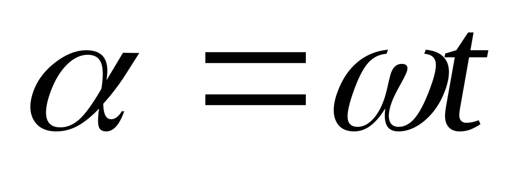
Operating principle
applied to the stator winding AC voltage, under the action of which a current flows through these windings and creates a rotating magnetic field. The magnetic field acts on the rotor winding and, according to the law of electromagnetic induction, induces an EMF in them. In the rotor winding, under the action of the induced EMF, a current arises. The current in the rotor winding creates its own magnetic field, which interacts with the rotating magnetic field of the stator. As a result, a force acts on each tooth of the rotor magnetic circuit, which, adding up around the circumference, creates a rotating electromagnetic moment that causes the rotor to rotate.
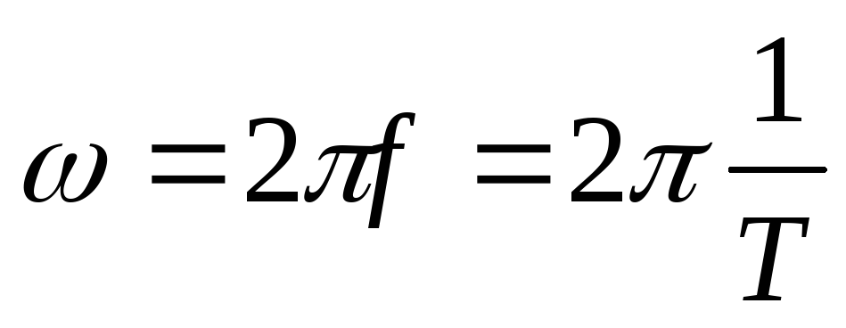
Stator field rotation speed
When the stator winding is supplied with a three-phase (in the general case, multi-phase) current, a rotating magnetic field is created, the synchronous rotation frequency [rpm] of which is related to the mains frequency [Hz] by the ratio:
,where is the number of pairs of magnetic poles of the stator winding.
Depending on the number of pairs of poles, the following values of the rotational frequencies of the stator magnetic field are possible, at a supply voltage frequency of 50 Hz:
| n, rpm | |
|---|---|
| 3000 | 1 |
| 1500 | 2 |
| 1000 | 3 |
| 300 | 10 |
Most motors have 1-3 pairs of poles, rarely 4. More poles are used very rarely, such machines have low efficiency and power factor, but they allow the motor rotor to rotate very smoothly and slowly.
Operating modes
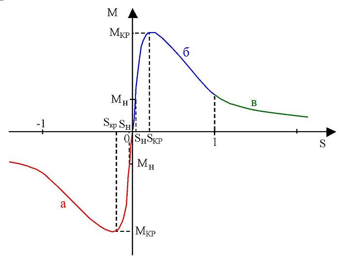
Mechanical characteristics of an asynchronous machine: a - energy recovery mode to the network (generator mode), b - motor mode, c - counter-inclusion mode (electromagnetic brake mode).
Motor mode
If the rotor is stationary or its rotation frequency is less than synchronous, then the rotating magnetic field crosses the conductors of the rotor winding and induces an EMF in them, under the action of which a current appears in the rotor winding. Electromagnetic forces act on the conductors with the current of this winding (or rather, on the teeth of the rotor core); their total force forms an electromagnetic torque that drags the rotor along with the magnetic field. If this moment is sufficient to overcome the friction forces, the rotor starts to rotate, and its steady rotational speed [rpm] corresponds to the equation electromagnetic torque brake, created by the load on the shaft, friction forces in bearings, ventilation, etc. The rotor speed cannot reach the magnetic field speed, since in this case the angular speed of the magnetic field rotation relative to the rotor winding will become equal to zero, the magnetic field will cease to induce in the rotor winding EMF and, in turn, create torque; Thus, for the motor mode of operation of an asynchronous machine, the inequality is true:
.The relative difference between the frequencies of rotation of the magnetic field and the rotor is called sliding:
.It is obvious that in the motor mode .
generator mode
If the rotor is accelerated with the help of an external torque (for example, by some motor) to a frequency greater than the frequency of rotation of the magnetic field, then the direction of the EMF in the rotor winding and the active component of the rotor current will change, that is, the asynchronous machine will go into generator mode. At the same time, the direction of the electromagnetic torque will also change, which will become braking. Slip in generator mode.
To operate an asynchronous machine in generator mode, a reactive power source is required that creates a magnetic field. In the absence of an initial magnetic field in the stator winding, the flux is created using permanent magnets, or with an active load due to the residual induction of the machine and capacitors connected in parallel to the phases of the stator winding.
An asynchronous generator consumes reactive current and requires the presence of reactive power generators in the network in the form of synchronous machines, synchronous compensators, static capacitor banks (BSK). Because of this, despite the ease of maintenance, asynchronous generator are used relatively rarely, mainly as low-power wind generators, auxiliary sources of low power and braking devices. But the generator mode of an asynchronous motor is used quite often. In this mode, the engines of the subway escalators work, which go down. In the generator mode, the elevator engines operate, depending on the ratio of weight in the cabin and in the counterweight.
Idle mode
The idle mode of an asynchronous motor occurs when there is no load on the shaft in the form of a gearbox and a working body. From the experience of idling, the values of the magnetizing current and the power losses in the magnetic circuit, in the bearings, and in the fan can be determined. Real idle s=0.01-0.08. In perfect idle mode n 2 =n 1 , therefore s=0 (in fact, this mode is unattainable, even under the assumption that friction in the bearings does not create its own load torque - the very principle of the engine operation implies that the rotor lags behind the stator field to create a rotor field. When s=0 the stator field does not cross the rotor windings and cannot induce current in it, which means that the rotor magnetic field is not created.)
Electromagnetic brake mode (option)
If you change the direction of rotation of the rotor or the magnetic field so that they rotate in opposite directions, then the EMF and the active component of the current in the rotor winding will be directed in the same way as in the motor mode, and the machine will consume active power from the network. However, the electromagnetic moment will be directed opposite to the load moment, being a braking one. The following inequalities hold for the regime:
This mode is used for a short time, since during it a lot of heat is generated in the rotor, which the engine is not able to dissipate, which can damage it.
For softer braking, the generator mode can be used, but it is effective only at revolutions close to the nominal ones.
Ways to control an asynchronous motor
Under the control of an asynchronous AC motor is meant a change in the rotor speed and / or its torque. There are the following ways to control an asynchronous motor:
- rheostatic - changing the speed of rotation of the IM with a phase rotor by changing the resistance of the rheostat in the rotor circuit, in addition, this increases the starting torque;
- frequency - change in the speed of rotation of the HELL by changing the frequency of the current in the supply network, which entails a change in the frequency of rotation of the stator field. The engine is switched on via frequency converter;
- switching the windings from the "star" circuit to the "triangle" circuit in the process of starting the engine, which reduces the starting currents in the windings by about three times, but at the same time, the torque also decreases;
- pulsed - by supplying a special type of supply voltage (for example, sawtooth);
- the introduction of additional emf according to or opposite to the slip frequency in the secondary circuit;
- change in the number of pairs of poles, if such switching is provided constructively (only for short-circuit rotors);
- by changing the amplitude of the supply voltage, when only the amplitude (or effective value) of the control voltage changes. Then the control and excitation voltage vectors remain perpendicular (autotransformer start);
- amplitude-phase method includes two methods described;
- inclusion in the power circuit of the stator of reactors;
Notes
see also
- Veshenevsky S. N. Characteristics of motors in an electric drive. Edition 6, revised. Moscow, Energia Publishing House, 1977. Circulation 40,000 copies. UDC 62-83:621,313.2
Links
- The device and principle of operation of asynchronous electric motors
- Gaidullin Alexander "Assembly of an asynchronous motor 4A200"
- Asynchronous electric motor of three-phase current M. O. Dolivo-Dobrovolsky
| |||||||||||
The device of an asynchronous machine. The stationary part of an AC machine is called the stator, and the moving part is
rotor. The stator and rotor cores of asynchronous machines are assembled from sheets of electrical steel (Fig. 19-1), which are usually coated on both sides with an oil-rosin insulating varnish before assembly. The cores of low-power machines are sometimes assembled from unvarnished sheets, since in this case a natural or artificially created layer of oxides on the surface of the steel sheets is sufficient insulation.
On fig. Figure 19-2 is an exploded view of a small power induction motor showing the stator, rotor and end shields. On fig. 19-3 is a drawing of a medium power induction motor.
Rice. 19-1. Stator core sheets (1) and rotor (2) of an asynchronous machine of small and medium power
The stator core is fixed in the housing, and the rotor core - on the shaft^ (machines of low and medium power) or on a rim with a stub and a sleeve put on the shaft (high power machines) The rotor shaft rotates in bearings that are placed in bearing shields attached to the stator housing (machine kovy "stacks 11 М0ШН0Стиi) "or on piece-mounted bearings
On the inner cylindrical surface of the stator and on the outer cylindrical surface of the rotor there are grooves,
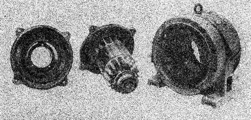
Rice. 19-2. Photo of an asynchronous motor with a squirrel-cage rotor type A71-6 with a power of 14 ket disassembled
in which the conductors of the stator and rotor windings are placed. The stator winding is usually three-phase (see Ch. 21); is connected to a three-phase current network and is therefore also called the primary winding. The rotor winding can also be made three-phase similar to the stator winding. The ends of the phases of such a rotor winding are usually connected into a star, and the beginnings are brought out with the help of slip rings and metal-graphite brushes (Fig. 19-3). Such an asynchronous machine is called a wound rotor machine. A three-phase starting or adjusting rheostat is usually connected to the slip rings. The phase winding of the rotor is performed with the same number of magnetic field poles as the stator.
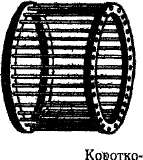
Another type of rotor winding is a winding in the form of a squirrel cage (Fig. 19-4). In this case, in each groove there is a copper or aluminum rod and the ends of all rods
from both ends of the rotor are connected with copper or aluminum rings, which short-circuit the rods. The rods are usually not insulated from the core. In machines up to 1QG k&p rods and rings, together with wings for ventilation, are usually made by pouring aluminum into the rotor
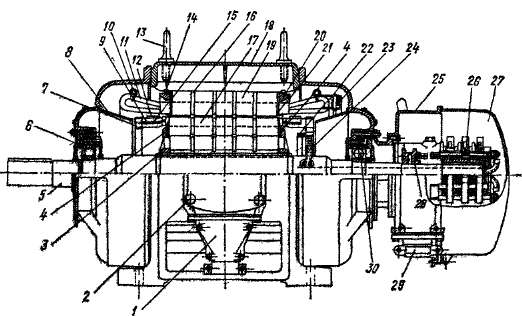
Figure 19-3 180 Three-Phase Wound Rotor Induction Motor ket,
975 rpm
1 - cable box, 2 - outlet box of the ends of the stator winding, 3 - ring dowels for fastening the rotor core, 4 - pressure washers of the rotor core, 5 - rotor shaft, 6 and 30 - ball and roller bearings, 7 - copper connecting collars of the rotor winding rods, 8 -^ diffusers for directing the incoming cooling air through the lining shields, 9 - winding rods^ of the rotor, "10 - retaining rings, // - stator winding, 12 - wire bandages! rotor, 13 - lifting rings, /* - arc keys, 15 - ring insulating gaskets, 16 - radial ventilation ducts, 17 - rotor core, IS->j cast stator housing, 19 - stator core, 20 and 21 - pressure pads and stator core ring, 22 - a ring for connecting the ends of the rotor winding into a star, 23 - «intercoil and intergroup connections of the stator winding, 34 - conclusions of coc* tsov of the rotor winding to slip rings,. 25 and 27 - box and cap of slip rings, 26 - contact rings, 28 - movable sleeve with contacts for closed^. the rotor winding leads are short-circuited, 29 - coupling for the output of rotra winding conds
to external circuit
(See Fig. J9-2). Such an asynchronous machine is called a squirrel-cage machine. Most of the chrono machines, especially small and medium power machines, come with a shorted gpTopOM.
The air gap between the stator and the rotor in asynchronous machines is the minimum possible in terms of production conditions and reliability of operation, and the larger the larger the machine, the larger. In machines with a power of several kilowatts, the gap
is 0.4-0.5 mm, and in machines of high power - a few millimeters.
Asynchronous machines are usually air cooled. The ventilation systems are in principle the same as for DC machines (see § 8-5).
Rotating magnetic field. On fig. 19-5 are cross sections of a bipolar (2p- 2) an induction motor and shows the nature of the stator magnetic field for two points in time.
On fig. 19-5 shows the simplest stator winding, when each phase consists of one turn or two conductors (1st phase - conductors BUT and x, 2nd phase - conductors AT and Y, 3rd phase - conductors FROM and Z) 1 . The conductors of each turn (phase) are located - from each other at a distance of pole division
where D a- the diameter of the internal bore of the stator, ar - the number of pairs of poles.
On fig. 19-5 pole division makes a closed winding ro-half of a circle. Pitch of coil or winder in the form of a squirrel's kee at therefore is complete (at= t). Two cells
360° el. Start of phases A, B, C shifted relative to each other by 120 ° el., which in this case is a third of the circle.
On fig. 19-5, a the directions of currents in the conductors of the stator winding are shown for the moment of time when i a - I m and i b= i c =
- - *)t- Phase currents in fig. 19-5 are considered positive when
they are at the beginning of the phases (conductors A, B, C) directed beyond the plane of the drawing. On fig. 19-5, b the directions of the currents are shown for the moment of time when the phases of the currents have changed by 30° and
From fig. 19-5 it can be seen that the distribution of currents around the circumference of the stator is two zones, each with a value of m, and the direction is
1 According to GOST 183-66, the beginning of the phases of the stator windings are designated C 1 (C 2, From 3 , their ends - respectively C 4, C 8, C g, and the beginning of the phases of the rotor windings - Pi, P 2 > ^z- In this book, for methodological purposes, the beginnings of three-phase windings are denoted everywhere A, B, C or a, b, c, and the ends - respectively L, Y, Z or x, y, g.
![]()
the currents in these zones are opposite. At the bottom of Fig. 19-5 shows the current distribution curves along the deployed stator.
| From these curves it can be seen that the currents are distributed on the surface of the stator according to a sinusoidal law. |
The currents of the conductors of the stator winding of a two-pole machine are created, as follows from Fig. 19-5, bipolar magnetic flux
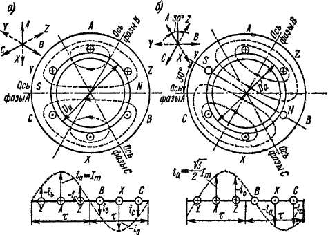
Rice. 19-5. The simplest stator winding of an asynchronous machine with 2p = 2 and its magnetic field
Ф 1 (passing through the stator, rotor and air gap between them. From the comparison of Fig. 19-5, ai b It can be seen that when the phase of the currents changes by 30°, the current distribution curve and the magnetic flux rotate in the direction of the phases also by 30° el.
The axis of the turn (winding) of the phase BUT in fig. 19-5 is directed horizontally, and the magnetic flux axis at i a = lm(Fig. 19-5, a) is also directed horizontally. It is clear that if the phase of the currents compared with Fig. 19-5, a will change by 120° and therefore will be i b \u003d I m , then the magnetic flux will be directed along the phase axis AT, i.e. will turn 120 ° el. At the point in time when i c- I m , the axis of the magnetic flux coincides with the axis of phase C, etc.
Thus, the stator winding of a two-pole machine, when powered by a three-phase current, creates a two-pole rotating magnetic field.
In this case, for one period of current change, the field rotates by 2 tons or 360 ° el.
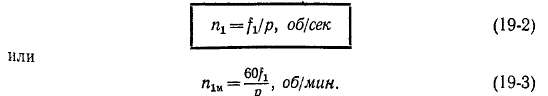
Field rotation speed
n i - h rpm,
where fi is the frequency of the stator current.
The magnetic field rotates in the direction of the phase sequence A, B, C stator windings. To change the direction of rotation of the field to the opposite, it is enough to change places on the clamps of the winding At ki stator ends of two conductors coming from the mains.
With 2p \u003d 4, the pole division is a quarter of a circle and each phase of the simplest three-phase stator winding (Fig. 19-6) consists of two turns with a step y = x, which are shifted relative to each other by 2 m and can be connected to each other in series or in parallel. Individual phases and their beginnings A, B, C while also shifted relative to each other by 120 ° el. or in this case 1/6 of the circle. From fig. 19-6 it can be seen that such a winding creates a current distribution curve and a magnetic field with 2p \u003d 4. This field is also rotating and for one
the period of the current also rotates by 2m, or in this case by half a circle, as a result of which the field velocity
p g = y, obIsec.
In the general case, it is possible to make a winding with 2p = 6, 8, 10, etc. In this case, a current distribution curve and a magnetic field with p pairs of poles will be obtained. The magnetic field rotates at a speed
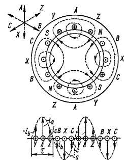
Rice. 19-6. The simplest winding
stator of an asynchronous machine with
2p - 4 and its magnetic field
Linear peripheral speed of rotation of the field along the circumference of the stator
At the standard industrial current frequency in the USSR / = 50 Hz the rotation speeds of the field are obtained, indicated in Table. 19-1.
Table 19-1
The speed of rotation of the magnetic field of windings with different numbers of pairs of poles R at L = 50 Hz
| R | ||||||||||
| Px, R/MUH |
When designing alternating current windings, they strive (see Chap. 21) so that the distribution of the induction of the rotating field in the air gap along the circumference is as close as possible to sinusoidal.
Later in this chapter, it will be assumed that this distribution is sinusoidal.
The principle of operation of an asynchronous machine. The magnetic flux Ф 1 (created by the stator winding (Fig. 19-5 and 19-6), during its rotation, crosses the conductors of the rotor winding, induces emf in them. e p, and if the rotor winding is closed, then currents arise in it c, the frequency of which f 2 with a stationary rotor (i \u003d 0) is equal to the primary frequency f t .
If the rotor winding is three-phase, then a three-phase current is induced in it. This current creates a rotating flux of the rotor F 2, the number of poles 2 p, the direction and speed of rotation of which at n = 0
same as the stator flux. Therefore flows F g and F a rotate synchronously and form a common rotating flow of the motor F. With a squirrel-cage rotor, a multi-phase system of currents % is induced in its rods with a phase shift in adjacent rods by an angle
![]()
where Z 2 is the number of rotor rods. These currents also create a rotating flux Ф 2, the number of poles, the direction and speed of rotation of which are the same as that of the phase rotor flux. Therefore, in this case, a common magnetic flux F is also formed in the engine. In view of the existence of a common rotating magnetic field, one can consider e. d.s., induced in the windings by this field.
As a result of the interaction of the rotor currents with the flow, mechanical forces acting on the conductors of the rotor arise F and rotating electromagnetic moment M.
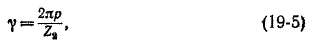
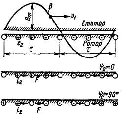
At the top of Fig. 19-7 shows a sinusoidal wave of the general magnetic field rotating at a speed i>i AT machines and directions e. d.s. e 2 induced by this field in the rods of a fixed squirrel-cage rotor. At the bottom of Fig. 19-7 shows the directions of the currents of the rods, c and the forces acting on them F for two cases: when the phase shift angle "fa between e, and r 2 is zero and when ■ph 2 \u003d 90, At% \u003d 0, all forces act in the direction of rotation-field. Therefore, the torque
Figure 19-7. Currents in the rods of the rotor winding and the forces acting on them
is different from zero and also acts in the direction of field rotation. At the same time, at t | e a \u003d 90 °, the forces act in different sides
and M= 0.
It follows that the torque is created only by the active component of the rotor current
This conclusion is of a general nature and is also valid for other types of AC machines.
The rotor circuit of an asynchronous motor always has a certain active resistance, and therefore, when starting the motor (n = 0) always 0< t|) 2 < 90°. В результате развиваемый момент M> Q, and if it is greater than the static braking torque on the shaft, then the motor rotor will begin to rotate in the direction of rotation of the field with a certain speed P<; p b i.e., it will rotate with some lag, or slip, relative to the stator field,
![]()
![]()
Relative difference between the speeds of rotation of the field and the rotor
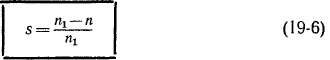
called slip. The slip is also expressed as a percentage:
Rotor speed P, expressed in terms of slip s, according to formula (19-6), is equal to
When starting the engine (P= 0) we have s = 1, and when the rotor rotates synchronous with the stator field or, as they say, with synchronous speed (P= p d) will be s = O. When n = n x the magnetic field of the stator relative to the rotor is stationary and the currents in the rotor will not be induced, therefore M= 0 and the engine cannot reach such a rotation speed. As a result, in engine mode it is always 0< /г <п х and l>s>0.
When the rotor rotates towards the field, the frequency of crossing the rotor conductors by the field is proportional to the speed difference tii- P and the frequency of the current in the rotor winding
Substituting the value here P from the formula (19-7) and then the value n x from (19-2), we get
i.e. the secondary frequency is proportional to the slip.
At current frequency / 2< f t the speed of rotation of the rotor field relative to the rotor itself n 2p is also less p g and based on the expression (19-9)
Rotation speed of the rotor field relative to the stator in accordance with expressions (19-7) and (19-10)
i.e. the speed of rotation of the rotor field relative to the stator at any speed of rotation of the rotor P equal to the rotation speed of the stator field p x. Therefore, the fields of the stator and rotor with a rotating rotor also always rotate synchronously and form a common rotating field.
Note that shown in Fig. 19-7 the picture of the directions of currents and mechanical forces is also valid when the rotor rotates, when 0< P< n x(motor mode).
If the rotor of an asynchronous machine with the help of an external force (torque) is brought into rotation in the direction of rotation of the stator field at a speed higher than synchronous (P> p d), then the rotor will overtake the field and directions of the currents induced in the rotor winding compared to those shown in Fig. 19-7 is reversed. In this case, the directions of electromagnetic forces are also reversed F and electromagnetic moment M. Moment M in this case, it will be braking, and the machine will work in generator mode and give active power to the network. According to expression (19-6), in generator mode s< 0.
If the rotor is rotated in the opposite direction to the direction of rotation of the stator field (P< 0), то указанные на рис. 19-7 направления е 2 , / 2 и F is saved. Electromagnetic moment M will act in the direction of rotation of the stator field, but will slow down the rotation of the rotor. This mode of operation of an asynchronous machine is called the counter-inclusion mode or the electromagnetic brake mode. In this mode, in accordance with the expression (19-6) s> 1.
The modes of operation of an asynchronous machine are discussed in more detail in the next section. Here, however, it should be noted that the relation (19-11), as it is easy to see, is preserved in any mode of operation, for any value of s, i.e., the fields of the stator and rotor rotate synchronously in any mode of operation of the asynchronous machine.
An asynchronous machine is a brushless AC machine in which a rotating magnetic field is excited during operation, but the rotor rotates asynchronously, i.e. with an angular velocity different from the angular velocity of the field.
Induction motors are the most common of all motors. Their advantages lie in the simplicity of the device, high reliability and relatively low cost.
Three-phase asynchronous motors proposed by M.O. Dolivo-Dobrovolsky in 1888. They are performed with a power from fractions of a watt to thousands of kilowatts, with a rotation frequency of 500 to 3000 rpm and a voltage of up to 10 kV. Single-phase asynchronous motors are used to drive household appliances, power tools, in automation circuits. They are powered by a single-phase circuit and have a power, as a rule, not higher than 0.5 kW.
Asynchronous machines can operate in generator mode. But as sources of electrical energy, they are almost never used, since they do not have their own source of excitation of the magnetic flux and are inferior to synchronous generators in terms of their performance.
Asynchronous machines are used as voltage regulators, phase regulators, frequency converters, etc.
The disadvantages of asynchronous machines are the complexity and uneconomical regulation of their performance.
An asynchronous motor consists of a stator, a rotor and end shields. The stator is the fixed part of the engine and has a cylindrical shape. It consists of a body, a core and a winding. The body is cast steel or cast iron. The stator magnetic circuit is assembled from thin sheets of electrical steel. On the inner surface, it has grooves into which the stator winding fits. The rotor of an induction motor - the rotating part - consists of a steel shaft, a magnetic circuit made of sheets of electrical steel with stamped grooves. The rotor winding can be short-circuited or phase. The short-circuited winding is made of aluminum or copper rods short-circuited at both ends of the rotor. The phase rotor has a three-phase winding connected to a star. The winding leads are connected to the rings on the shaft and are connected to a rheostat or other device with the help of brushes. The rotating rotor is placed on a common shaft with a stator. The shaft rotates in bearing shields. The connection of the stator winding is carried out in a box into which the beginnings of the phases C 1, C 2, C 3 and the ends of the phases C 4, C 5, C 6 are brought out. On fig. shows the layout of these conclusions (a) and ways to connect them to each other when connecting the phase windings with a star (b) and a triangle (c).
If two voltages are indicated in the motor passport, for example, 380/220, then a star connection corresponds to a higher voltage, a triangle connection to a smaller one. In both cases, the motor phase voltage is 220 V.
The three-phase stator winding creates a magnetic field that rotates at a speed 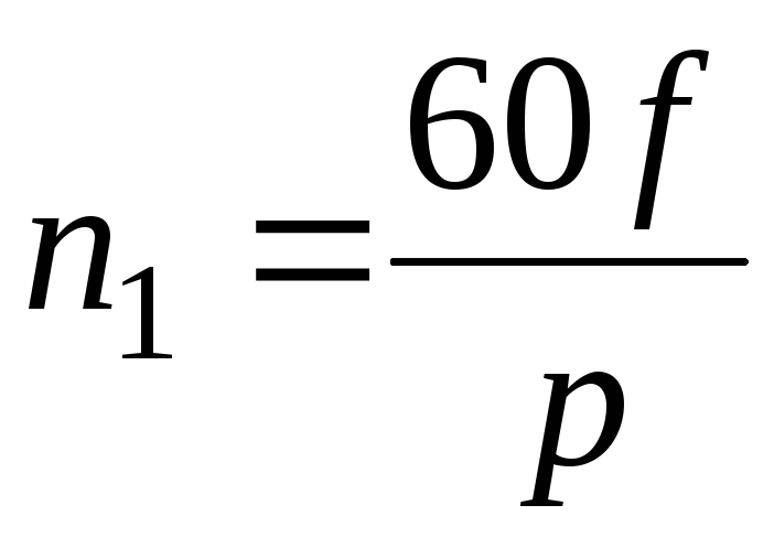 .
.
Electromagnetic interaction between the stator and the rotor occurs only when the speed of the stator field and the speed of rotation of the rotor are not equal.
Rotating magnetic field of the stator of an asynchronous machine. Frequency of rotation of the stator field, slip (Characteristics).
The basis of the action of an induction motor is a rotating magnetic field. The principle of obtaining a rotating magnetic field is that if phase-shifted currents flow through a system of conductors distributed in space along a circle, then a rotating field is created in space.
R 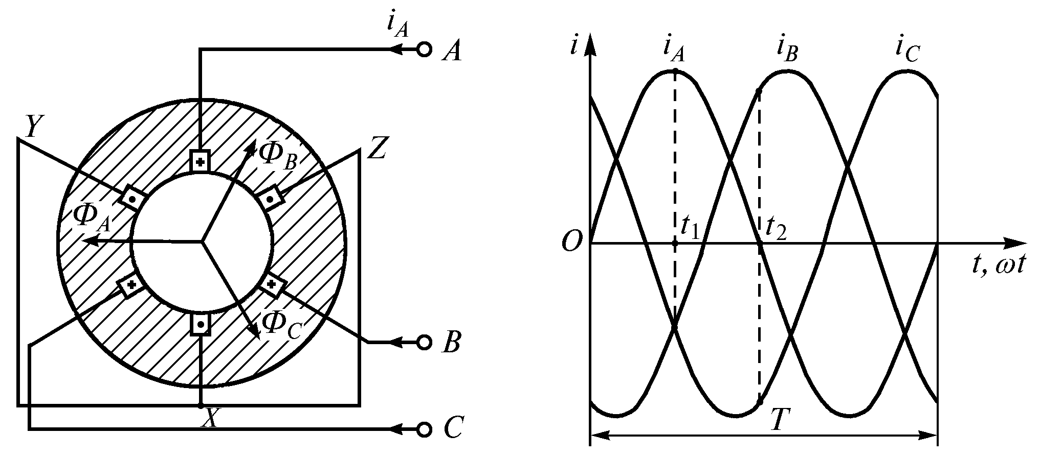 Consider obtaining a rotating field in a three-phase motor. On fig. 1 shows three phase windings A–
X,
B
– Y,
C
– Z, each in the form of a single coil. A three-phase system of currents is supplied from the power source to the windings
Consider obtaining a rotating field in a three-phase motor. On fig. 1 shows three phase windings A–
X,
B
– Y,
C
– Z, each in the form of a single coil. A three-phase system of currents is supplied from the power source to the windings 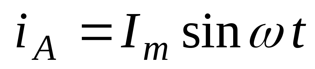 ;
;![]() ;
;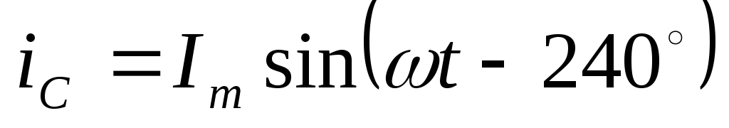 .
.
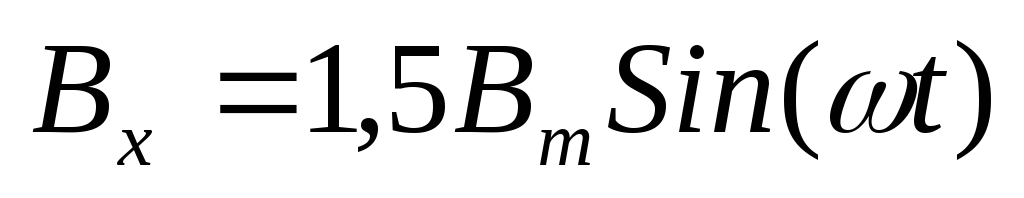
If the phases of the stator winding are connected to a 3-phase mains current, currents arise that create a magnetic field with induction: 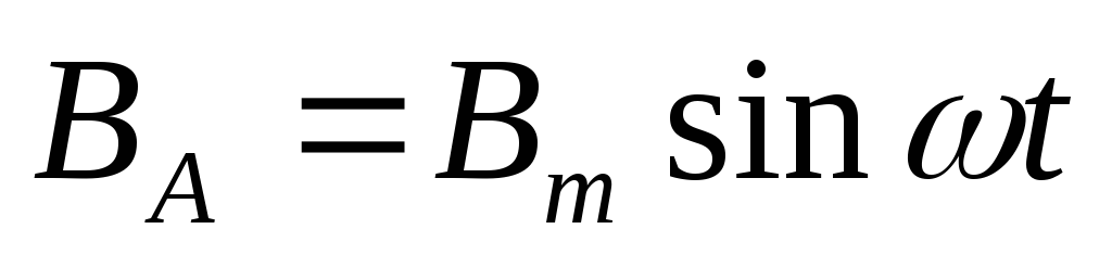 ;
;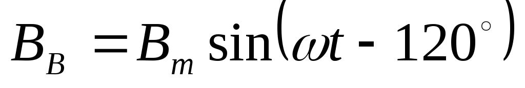 ;. The component of the field induction along the X axis is equal to the algebraic sum of the projections onto this axis of the instantaneous values of the inductions of individual phases, i.e.
 . Similarly, we find the projection on the Y axis.
 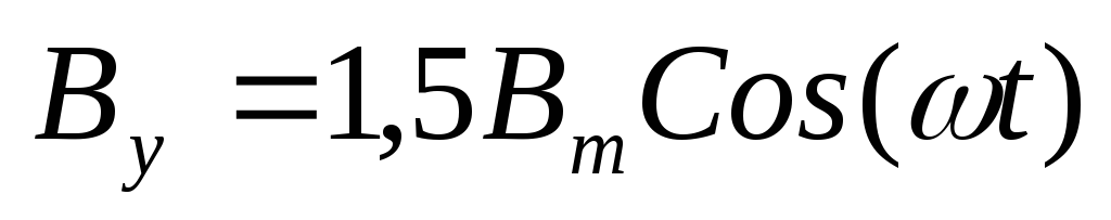 . As a result, the magnetic induction of the stator field is equal to:
The magnetic field induction is const, and the stator field itself has projections on the X and Y axes, respectively: 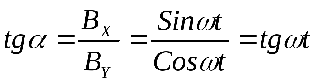
V-or induction of the cut-th field is located at an angle to the y-axis 
 ,
,
 , where T is the period of current change,
  -cyclic frequency
In this way, three-phase winding, fed by currents shifted by 120°, creates a rotating magnetic field. The resulting flow remains unchanged and is equal to 1.5 of the maximum flow of the phase. The direction of this flux always coincides with the direction of the magnetic flux of the phase in which the current is maximum at the given moment. Therefore, to change the direction of rotation, it is necessary to swap any two phases.
The examples considered refer to a two-pole winding design () at a field rotation frequency. In the general case, the frequency of rotation of the field, where is the number of pairs of poles of the machine; is the frequency of the stator current.
Value or 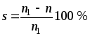 called sliding asynchronous machine, where
  - frequency of rotation of the stator field,
  - frequency of rotation of the rotor.
Depending on the ratio and there are three modes of operation: in engine mode; in generator mode; in electromagnetic brake mode.
Work in engine mode. The electromagnetic forces of the interaction of the magnetic fields of the stator and the rotor create a torque in the direction of rotation of the stator field. The speed at which the motor rotates depends on its load. At idle, the speed becomes almost equal, since at = 0 the EMF and the currents in the rotor are zero and the electromagnetic interaction disappears. Thus, the asynchronous machine operates in motor mode within the range from = 0 to, i.e. when sliding from +1 to 0. In this case, the electrical energy supplied to the stator from the network is converted into mechanical energy on the shaft.
Work in generator mode. Let us assume that the stator connected to the network creates a rotating magnetic field, and the rotor is driven in the same direction with a speed. In this case, the slip will be negative, and the EMF and rotor currents will change direction compared to the operation in motor mode. The torque on the shaft becomes braking in relation to the torque of the prime mover. An asynchronous machine works as a generator. The mechanical energy supplied to the shaft is converted into electrical energy and transferred to the network. Thus, an asynchronous machine can operate in the generator mode in parallel with the network within the limits of the otdo, i.e. when sliding off  before.
Work in the electromagnetic brake mode. Let us assume that the rotor is driven against the direction of rotation of the stator magnetic flux. In this case, energy is supplied to the asynchronous machine from two sides - electrical from the network and mechanical from the prime mover. This mode of operation is called electromagnetic brake mode. It occurs when sliding from to.
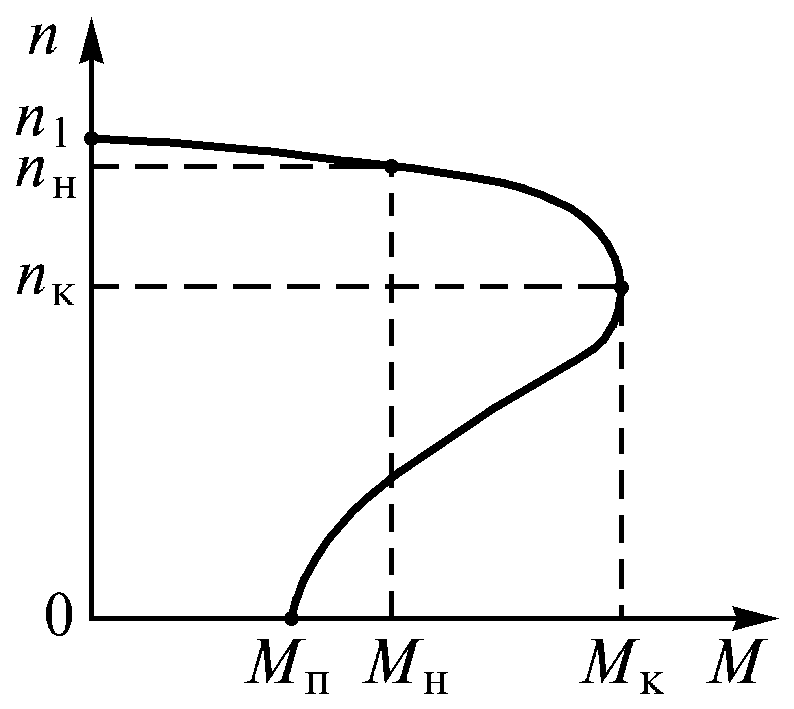
 - maximum moment
 - Starting torque
 - nominal moment
The mechanical characteristic of the engine is the dependence of the rotor speed on the torque on the shaft. Since the idle moment is small under load, the mechanical characteristic is represented by a dependence. If we take into account the relationship, then mechanical characteristic can be obtained by presenting its graphical dependence in coordinates
An asynchronous machine has a stator and rotor separated by an air gap. Its active parts are windings and a magnetic circuit (core); all other parts are structural, providing the necessary strength, rigidity, cooling, the possibility of rotation, etc.
The stator winding is a three-phase (in general, multi-phase) winding, the conductors of which are evenly distributed around the circumference of the stator and laid phase by phase in grooves with an angular distance of 120 °. The phases of the stator winding are connected according to standard "triangle" or "star" schemes and connected to a three-phase current network. The stator magnetic circuit is remagnetized in the process of changing the current in the stator winding, so it is recruited from electrical steel plates to ensure minimal magnetic losses. The main method of assembling the magnetic circuit into a package is blending.
According to the design of the rotor, asynchronous machines are divided into two main types: with short-circuited rotor and phase rotor. Both types have the same stator design and differ only in the design of the rotor winding. The rotor magnetic circuit is made similarly to the stator magnetic circuit - from electrical steel plates.
asynchronous machine- an alternating current electric machine, the rotor speed of which is not equal (in the motor mode less) to the frequency of rotation of the magnetic field created by the stator winding current.
In a number of countries, commutator machines are also classified as asynchronous machines. Another name for asynchronous machines is induction due to the fact that the current in the rotor winding is induced by the rotating field of the stator. Asynchronous machines today make up the majority of electrical machines. They are mainly used as electric motors and are the main converters of electrical energy into mechanical energy, and are mainly used asynchronous motors with a squirrel-cage rotor (ADKZ).
Advantages (for ADKZ):
- Ease of manufacture.
- Relative cheapness.
- High operational reliability.
- Low operating costs.
- Ability to connect to the network without any converters (for loads that do not need speed control).
All of the above advantages are a consequence of the absence of mechanical commutators in the rotor circuit and have led to the fact that most of the electric motors used in industry are asynchronous machines, performed by ADKZ.
Flaws:
- Small starting moment.
- Significant starting current.
- Low power factor.
- The complexity of speed control with the required accuracy.
- The maximum motor speed is limited by the mains frequency (for ADKZ powered directly from three-phase network 50 Hz is 3000 rpm).
- Strong dependence (quadratic) of the electromagnetic torque on the supply voltage (when the voltage changes by 2 times, the torque changes by 4 times; in DCTs, the torque depends on the armature supply voltage to the first degree, which is more favorable).
The most perfect approach to eliminate the above disadvantages is to power the motor through a frequency converter, in which control is carried out according to complex algorithms.


