Jul 03 2017
It is easier to use current clamps, only there is one but. At idle, even at high speeds, the engine is powerless to develop full power.
Below is a table according to which you can judge the parameters of the device by mode. Doesn't solve the problem entirely. Let's see how to determine the power and current of an electric motor with simple methods.
Determining the motor current
It is easier to use current clamps. A device that allows you to remotely assess the magnitude of tension magnetic field around a single wire.
Covering the power cord with a ring, we get a value equal to zero. The fields are directed oppositely to the phase and zero conductors.
You will need to work to make an outlet with separate wires, shown in the picture.
Here we see:
- Wooden base. The obvious way out, it is customary to mount the socket on the insulator. It's easier to get a small piece of board.
- The surface-mounted socket is shown disassembled: the base, the body are located separately.
- Remove the insulation from the power cord to cover each core separately.
- Find a collapsible plug. It is forbidden to use for powerful instruments, but we will take measurements for a short period of time, accompanied by full control. Or buy a standard extension cord in the store, remove the outer insulation from the power cord.
 The socket is mounted on the board, take the trouble to securely clamp the wires, blocking the possibility of breaking, slipping.
It's easier to do it by using the insulation trim, the photo is shown. We press it with a self-tapping screw, the long life of the test outlet is ensured.
When putting on the case, you will need to wind a little electrical tape around the cord for better pressing.
It turned out to be an auxiliary tool for carrying out measurements with current clamps.
At idle, the value will be lower than the nominal value.
It has been noticed that during acceleration, full power is required from the engine, instantaneous, given out by the pincer screen, are close to nominal.
For example, for the device in the photo - 3.2 A, with a voltage of 231 volts, it gives 740 W (nominal 750 W). At startup, it will be seen: the current rises sharply, then quickly drops. You need to have time to spot the top of the mountain.
Note: current clamps give readings at regular short intervals, it is difficult to detect the peak the first time.
Set the spindle speed to the highest, patiently pull the trigger, trying to catch the top. We succeeded the third time.
To take a more or less suitable picture, the experiment was carried out a dozen and a half times (the shutter was released with a delay, it was difficult to catch the moment).
And after that, the photo turned out to be only 3.1 A (we think readers believe the authors about 3.2 A).
During the experiment, a value of 4 A was obtained once, which we attribute to random jumps in the network current plus errors.
You make sure: the peak is repeated (at least 2 times out of five).
As a result, the power of the collector motor of an electric drill is approximately determined. We want to say right away: there is no unambiguous dependence of the idle current on the power rating.
In nature, there are quite complex formulas, it is quite difficult to use them. Practical application is more difficult. We give a table of approximate ratios asynchronous types engines.
 The information makes it possible to understand how to estimate the rated power of the motor by the no-load current.
The voltage must be rated, bulky devices need to be warmed up before work.
So says GOST R 53472. The period is determined by the type of bearings.
Be afraid to make a mistake, take the maximum value:
- Up to 1 kW of power, the warm-up time is below 10 minutes.
- Rated power 1 - 10 kW, warm-up time about half an hour.
- Rated power 10 - 100 kW, warm-up time up to an hour.
- Rated power 100 - 1000 kW, warm-up time up to two hours.
- Rated power over 1 MW, warm-up time up to three hours.
How to estimate the approximate power? We explain. The list is given to those wishing to take measurements more precisely.
For a rough estimate, we use the table, avoiding brainwashing. The collector motor of the drill did not warm up at all before measurements at room temperature.
Most readers are devoid of current clamps. Most multimeters allow you to measure current, the scale is limited to 10 A.
note , at the maximum limit, the red wire should be connected to another socket (shown in the photo) .
Near the hole in Russian ( English language) it is written: the time of operation with the measurement mode does not exceed 10 seconds (MAX 10SEC) followed by a quarter-hour break (EACH 15MIN). Otherwise, the multimeter operation is not guaranteed, the input is without a fuse (UNFUSED).
Tells the instructions. The multimeter crashes into the circuit. One wire needs to be opened for measurements. Together we will think about whether it is economically profitable.
Look at the picture of the receipts. The clampmeter means current clamps, a simple tester is designated 1SK.
It can be seen that both devices cost less than 400 rubles, because the household needs both.
The multimeter will allow you to evaluate the current up to 10 A, a very short operating time. The pliers work much rougher, one scale reaches the limit of 1000 A.
The conclusion is obvious - it is required to approximately determine the current of the electric motor, a "terminal" is used. You need accuracy, use a tester ( rated current below the limit).
Measure motor power
The power of the electric motor is composed of active, reactive components. Enterprises are subject to a penalty fee. Therefore, it is important to understand the measured quantities.
The current clamp instruction writes: RMS current is estimated. Pure mathematics.
This means: the device makes a sample of a certain interval, takes the root of the sum of the squares of individual measurements, divided by the total number.
Let's compare it to averaging over a certain period of time. Active current, full, reactive (hardly). The question needs to be clarified: the current clamps shown in the photo, with enviable regularity, give the power of the devices 11% below the nominal value.
Read also:
Checked electric heaters, irons, hair dryer. Power is underestimated by a single value. The literature says: Root Mean Square (RMS) shows the total amount of current.
Physically flows through the wire. The calculation is carried out for a sinusoidal form, there will be deviations if the requirement is not met.
Current clamps simply lie. If they showed the active part, for the engine the values \u200b\u200bwould be significantly lower than for the heater. The load is purely active, the windings give a strong imaginary component.
The current clamp must be calibrated before use. The easiest way to do this is using purely active heaters (oil). The ability of current clamps to measure active power separately is usually indicated in the instructions.
Professionals say: such products are the product of the imagination of amateurs
Engines give a large load in the reactive spectrum. People put up, or put capacitor units that compensate for the inconsistency, aligning the phase. You can read about such household products on websites selling appliances like Ekonor.
The meaning of the box is like a block of capacitors to compensate for reactive power. Please note: for professional stations, the limit expressed by VAR is indicated, for Econor the parameter is hushed up. One radio amateur counted the figure. It turned out that 150 VAR is compensated.
Probably enough for low-power devices, the engines will be elephant pellets. Asynchronous machines give 40% reactive power, energy is wasted. The benefits are pennies.
Please note: with an isolated neutral, problems are added. Current flows in one phase, leaves - the other. The effect can be subtracted.
The neutral is isolated - it turns out that the effect of one wire will be measured twice: input, output. Try adding the three values, then dividing by two. A rough method will be approximately correct.
Calculate the power consumption of the engine
We propose to determine the type of engine. Helps to make a badge. The apparent power is indicated (reactive plus active, connected through the cosine of the phase angle, called the power factor).
If the type of engine is known (found out, guided by the images, appearance), reference books will allow you to find the power.
No wonder: the dimensions are closely related to the parameter, each manufacturer wants to save as much as possible with the release of products.
Dimensions are optimized, a typical set of parameters is as follows:
- Shaft diameter.
- The height of the axis from the base (bed).
Accordingly, it is possible to understand the details without tools. You will see that information of a similar kind can be found for almost any type of motor.
The nameplate has been torn off, you can spend some time looking for similar models on the Internet. Russia is inferior to China in the variety of electric motors. The chance of success is high.
We believe that we have listed the available methods for determining power and current.
It is not a big problem to spend 1000 rubles, getting the necessary funds.
Considering that the ruble is burning, the move will seem reasonable.
It is easier to determine the power of an electric motor using a reference book. The shaft must be measured with a caliper.
We finish the review, we hope regular readers know the differences induction motor from the collector. We omit the differences.
Please also note: Asynchronous motors suffer from a large starting current. The collector spread is low.
Active power and losses. Recall that the power consumed by the engine electric power converted to mechanical. This power is active power. As in any other machine, the power consumed by the motor from the network P 1 differs from the power on the motor shaft P 2 by the value of the power losses in the motor itself ∆ P, i.e. P 1 = P 2 + ∆P.
Naturally, the smaller the loss ∆ P, the greater the efficiency of the engine. The power of losses heating the machine is the sum of the power of electrical, magnetic and mechanical losses. Electrical losses ∆ R E occur in the stator and rotor windings, i.e. ∆ R E \u003d ∆ R E1 + ∆ R E2 (here ∆ R E1 - losses in the stator winding and ∆ R E2 - losses in the rotor winding). Magnetic losses in the magnetic circuit ∆ R M1 arise due to the phenomena of hysteresis and eddy currents in the stator ∆ R M1 and in the rotor ∆ R M2, i.e. ∆R M = ∆R M1 + ∆R M2.
Mechanical losses are caused by friction forces in the bearings, in the sliding contact (brush - ring), and the rotor against the air ∆Р MEX. Based on the above
R 1 \u003d R 2 + ∆ R E1+∆R E2 + ∆R M1 + ∆R M2 + ∆R MEC. (3.29)
Expression (3.29) can be simplified if we neglect the magnetic losses in the rotor package due to their smallness in comparison with other terms. Indeed, the frequency of the rotor current within the limits up to the rated load is 1-4 Hz. At such a current frequency, and hence the loss fields due to hysteresis and eddy currents in the rotor are very small. Therefore, one can practically assume that
R 1 \u003d R 2 + ∆ R E1+∆R E2 + ∆R M1 + ∆R M2 + ∆R MEX (3.30)
Electromagnetic power and shaft power. The power transmitted by the magnetic field from the stator to the REM rotor is the power consumed from the network minus the losses in the stator, i.e.
R EM \u003d R 1 - ∆R E1 - ∆R M1 (3.31)
Power can be represented as the product of the moment and the angular velocity Ω 1, i.e.
R EM = Ω 1 M (3.32)
Mechanical power of the rotor R MEX , rotating with angular velocity Ω, can be represented as
R MEX = ΩM (3.33)
The losses in the rotor are ∆R E2 , That's why
REM = RMEX + ∆R E2 (3.34)
Motor shaft power R 2 differs from mechanical by the value of mechanical losses ∆P MEX , i.e.
R 2 = R MEX – ∆P MEX (3.35)
Based on the introduced concepts and formulas (3.30) - (3.35), for better clarity, it can be shown using the energy diagram shown in Fig. 3.20, power distribution and losses in an asynchronous motor. If we substitute into the formula (3.34) the power values through the moments (3.32) and (3.33), then we can show that the electrical losses of the rotor are proportional to the slip.
 The closer the rotor speed to the field speed, the less electrical losses. It should be noted that the magnetic losses ∆Р M
when the engine load changes from idle to nominal, as well as in a transformer, are constant value, i.e., do not depend on the load.
The closer the rotor speed to the field speed, the less electrical losses. It should be noted that the magnetic losses ∆Р M
when the engine load changes from idle to nominal, as well as in a transformer, are constant value, i.e., do not depend on the load.
Mechanical losses ∆ R MEX also practically independent of the load.
engine efficiency. Engine efficiency is the ratio of useful power, i.e. power on the engine shaft (passport_power) R 2 , to the power consumed from the network, i.e. .
If the constant losses are denoted by ∆ R s(∆R c \u003d ∆R m +∆ R fur), and variable losses ∆ R uh, That
![]() Engine efficiency varies with engine load, so the load factor must be taken into account in the efficiency formula. Since variable electrical losses ∆ R
uh are proportional to the square of the current, the efficiency formula is similar to the efficiency formula for a transformer, i.e.
Engine efficiency varies with engine load, so the load factor must be taken into account in the efficiency formula. Since variable electrical losses ∆ R
uh are proportional to the square of the current, the efficiency formula is similar to the efficiency formula for a transformer, i.e.
![]() .
(3.36)
.
(3.36)
Typically, the efficiency of an induction motor is 0.75 - 0.95.
The greater value of efficiency has an engine of greater power. The graph constructed according to (3.36) is shown in Fig. 3.21.
Power factor.
In addition to active power P
1
, the motor consumes reactive power Q
1
, mainly necessary for the formation of a rotating magnetic field. Power factor at sinusoidal current
 At idle cos φ
1
has a small value (about 0.1), since the active power is consumed only for relatively small losses in the stator and small mechanical losses, and the reactive power has a constant value, since the magnetic flux is constant.
At idle cos φ
1
has a small value (about 0.1), since the active power is consumed only for relatively small losses in the stator and small mechanical losses, and the reactive power has a constant value, since the magnetic flux is constant.
As the load increases, the active power increases, while the reactive power remains unchanged up to the rated load. As a result cos φ 1 increases, however, with a further increase in the load, an increase in the leakage flux affects, i.e., the reactive power increases and cos φ 1 starts to decrease. The power factor versus motor load curve is shown in fig. 3.21.
Considering the foregoing, it should be concluded that it is necessary to strive to ensure that the engine operates at a load close to the nominal (β = 1) .
KINEMATIC CALCULATION OF A MECHANICAL DRIVE
Sequence of kinematic calculation
Drive shaft power,kW
Where F t– circumferential force, kN; V- speed, m/s.
Drive shaft speed,min -1
A) For chain and slat conveyors
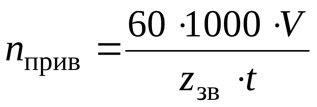 ,
,
Where z sv- the number of teeth of the traction sprocket; t- step of the traction sprocket, mm.
B) For belt conveyors, travel and turning mechanisms, disk feeder, winches, etc.
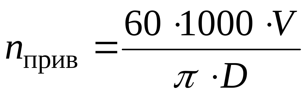 ,
,
Where D- diameter of the actuator, mm.
Overall drive efficiency
![]() ,
,
Where 

 ... - The efficiency of individual links of the kinematic chain, the approximate values of which are recommended to be taken from table 1.
Table 1.
Guideline values for the efficiency of the components of the drive
|
Links of the kinematic chain |
Designation | |
|
Gears: cylindrical closed cylindrical open conical closed conical open |
| |
Worm gear closed |
| |
|
Belt drives open: V-belt flat-belt |
| |
|
Chain transmission open |
| |
|
Coupling |
| |
|
Bearings (one pair): slip |
|


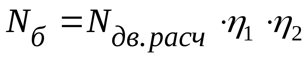
Estimated motor power,kW
 ,
,
Where  - power on the drive shaft, kW.
Motor selection
It is necessary to select an AC motor with a power
 (kW) closest to
  .
.
When selecting, it is allowed to overload the engine up to 6% at a constant load. Estimate the motor overload using the formula:  , Where
  - the smallest of the power values
  And
And  .
.
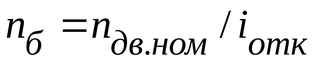
Power value corresponds, as a rule, to four electric motors with a certain synchronous speed:
 =
750; 1000; 1500; 3000min -1
. At a constant load, the calculation of the drive is carried out according to the rated speed of the electric motor
=
750; 1000; 1500; 3000min -1
. At a constant load, the calculation of the drive is carried out according to the rated speed of the electric motor  . AC motors of the AIR series are presented in Table 2.
Table 2.
Technical data of AIR series engines
|
Power N, kW |
Synchronous frequency, rpm |
|||
Notes.
Above the line is the type of engine, below the line is the rated speed.
Engine designation example: “AIR100 engineL2 TU 16-525.564-84"
Overall Drive Ratio
 , Where
  - frequency of rotation of the drive shaft, min -1
.
- frequency of rotation of the drive shaft, min -1
.
Calculated for each value of the rated speed of the electric motor at the assigned power .
Breakdown of overall drive ratio
A) Assign the gear ratio of the open gear of the drive  according to the recommendations of the table. 3, taking into account the following: a smaller gear ratio is preferable, which will provide smaller transmission dimensions.
Table 3
Values of gear ratios of mechanical gears
|
Transmission type |
gear ratio |
|
|
limiting |
||
|
Toothed cylindrical: closed; open | ||
|
Gear bevel: closed; open | ||
|
worm | ||
|
belt | ||
|
Planetary simple single row | ||
For a gear train, the gear ratio must be matched to the standard range of nominal gear ratios u according to GOST 2185:
1st row: 1; 1.25; 1.6; 2.0; 2.5; 3.15; 4.0; 5.0; 6.3; 8.00; 10; 12.5...
2nd row: 1.12; 1.4; 1.8; 2.24; 2.8; 3.55; 4.5; 5.6; 7.1; 9.0; 11.2…

Where n is an integer.
 .
.
Note
.
If there is no open gear in the drive, then  .
.
C) For a gear reducer, the gear ratio must be adjusted to the standard series of nominal gear ratios u
according to GOST 2185; for a worm gearbox with a single start worm, the gear ratio is an integer. In this case, the deviation of the actual gear ratio of the gearbox  from nominal
  should not exceed 2.5% at
  4.5 and 4% at 4.5.
The deviation is estimated by the formula: 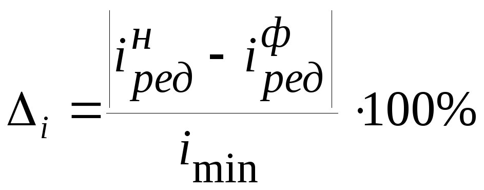 ,
,
Where  - the smallest of the gear ratio values of the gearbox And .
Note.
For single stage gearbox  ,
,
Whereu- nominal gear ratio of the gear stage.
Specify the type of electric motor for the assigned breakdown of the drive gear ratio (Table 2).
Power per drive shaft,kW:
Where 
 ... - efficiency of individual links of the kinematic chain.
Drive Shaft Speed,min -1 :
high speed gear shaft
 when connected with a coupling;
 in the presence of an open transmission;
 when connected with a coupling;
 with an open transmission.
Torque on each drive shaft,Nm:
 ,
,
Where i – drive shaft index.


