Send your good work in the knowledge base is simple. Use the form below
Students, graduate students, young scientists who use the knowledge base in their studies and work will be very grateful to you.
Hosted at http://www.allbest.ru/
Ukrainian state academy railway transport
Center for Scientific and Practical Training
from the discipline "Electrical Engineering"
"Engine direct current with parallel excitation
Plan
1. Introduction
2. DC motor design
3. Starting engines
4. Technical data of motors
5. Characteristics of DC motor
6. Mechanical characteristic
7. List of used literature
A DC motor (DC motor) is a converter of direct current electrical energy into mechanical energy. The design of the engine is shown in Fig.1. It has three main parts: the stator (inductor), armature and collector.
The inductor (1) - the fixed part of the machine, is a hollow cast steel cylinder made of electrical steel, to which inside cores (poles) are fastened with bolts. On the cores there is an excitation winding (OB) connected to the brushes. The inductor is designed to create the main magnetic field. The anchor (2) (rotating inner part of the machine) is a cylinder assembled from steel sheets. An anchor winding is laid in the grooves of the armature. Collector (3) is fixed on the same shaft with the armature, which is a hollow cylinder made up of individual copper plates (lamellas) isolated from each other and from the armature shaft and electrically connected to individual parts of the armature winding. The purpose of the collector is the mechanical rectification of variable sinusoidal EMFs into a constant voltage in magnitude and direction, which is removed to the external circuit using brushes adjacent to the collector. The properties of DC motors are mainly determined by the way the field winding is powered. In this regard, DC motors are classified into 2 types: with independent arousal(Fig. 2a) and self-excitation (Fig. 2 b, c, d)
The excitation winding in a DCT with independent excitation is powered by a separate DC source (from a semiconductor rectifier, battery or exciter - DC generator).
In self-excited DCTs, the armature and inductor circuits are electrically connected, i.e. the excitation winding is powered by the EMF of the armature of the machine.
Depending on the electrical circuit the connections of the armature windings and the inductor of a machine with self-excitation are further divided into three types: parallel, series and mixed excitation (Fig. 2 b, c, d). DPT, like all electrical machines, is reversible, i.e. they are without significant constructive
changes can work both in the mode of the generator, and in the mode of the engine. DPT operation mode with parallel excitation. Consider the operation of a DPT with parallel excitation (Fig. 2b). When the motor is connected to a DC network, currents arise in both windings. In this case, in the excitation winding, the excitation current IB creates a magnetic field of the inductor.
The interaction of the armature current with the magnetic field of the inductor creates an electromagnetic moment of the ME.
ME = sFIYA, (1)
where c is a constant coefficient;
IЯ - armature current;
Ф - magnetic flux.
The electromagnetic moment of the ME differs from the moment of the MW on the motor shaft by the value of the moment of idling losses MHH, which, due to its smallness, can be neglected and assumed that
A back-EMF E is induced in the conductors of the rotating armature:
where n is the rotation speed of the armature;
k is a constant factor.
The electrical equilibrium equation of the engine has the form:
U \u003d E + IЯ RY \u003d knФ + IЯ RY, (3)
where U is the mains supply voltage.
Starting the engine
When starting the engine, the armature is stationary at the first moment (n = 0) and given (2) the EMF of the armature E = knF = 0. In this case, according to (3), the starting current of the armature IYaP is unacceptably large, because R is small and is defined as:
Therefore, to limit the starting current, the resistance of the starting rheostat RP is introduced in series into the armature circuit, which is fully introduced before starting the engine and is output after the engine accelerates as the back EMF (E) increases.
Such a start of the engine protects its armature winding from high starting currents INP and allows you to get the maximum magnetic flux in this mode.
If the engine is started at idle, then there is no need to develop the maximum torque MB on the shaft. Therefore, the engine can be started by smoothly increasing the supply voltage U.
Reversingengine.
Changing the direction of rotation of the motor can be achieved by changing the current either in the armature winding or in the field winding, because this changes the sign of the torque. Simultaneous change in the direction of current in both windings does not change the direction of rotation of the motor. Switching of the ends of the windings should be carried out only after the engine has completely stopped.
Regulationspeedrotation.
From expression (3) it is possible to determine the rotation speed of the engine:
motor direct current supply winding
From formula (6) it can be seen that the speed of rotation of a DC motor can be controlled by changing the mains voltage, the excitation magnetic flux and the resistance of the armature circuit. The most common way to control the speed of rotation of the motor is to change the magnetic flux by means of an adjusting rheostat in the excitation circuit.
Reducing the excitation current weakens the magnetic flux and increases the speed of rotation of the motor. This method is economical, because the excitation current (in parallel excitation motors) is 3-5% of the armature IN, and the heat losses in the control rheostat are very small. Main Features of DC Motor with Parallel Excitation
The operation of a DC motor with parallel excitation is evaluated by the following main characteristics:
Idling characteristic: (fig.3)
n0 = ѓ (IB), with U = UN = const and IЯ = I0,
where n0 is the idle speed (no load),
I0 - no-load current of 5 - 10% IH;
UN - nominal value mains voltage.
Taking into account that at idle the product IЯRЯ is small compared to U, then from (6) the engine speed is determined by the inverse relationship to the magnetic flux Ф:
With an increase in the current in the excitation winding, the magnetic flux changes along the magnetization curve Ф = ѓ (IВ), so the relationship between the motor rotation speed n and the excitation current IВ is almost hyperbolic. At low values of the excitation current, the revolutions change almost inversely. At high excitation currents,
the magnetic saturation of the steel poles has an effect, and the curve becomes flatter and runs almost parallel to the abscissa axis. A sharp change - a decrease in the excitation current, as well as an accidental open circuit of the excitation circuit according to (9) can cause the motor to "run" (when IВ > 0, and therefore Ф also tends to 0, n > ?).
Mechanical characteristic. This is the dependence of the rotor speed on the MW torque on the motor shaft at a constant mains supply voltage and excitation current:
n \u003d ѓ (MV), with U \u003d UH \u003d const, IВ \u003d const.
For a parallel excitation motor, the moment MV is proportional to the first degree of the armature current IЯ. Therefore, the mechanical characteristic can be represented by the dependence n (Ib), which is called electromechanical or speed (Fig. 4).
A load (braking torque) is applied to the motor shaft. According to (6), at constant values of the excitation current, a decrease in the rotation speed n is a consequence of the voltage drop in the armature circuit - IЯ·RЯ and the armature reaction. With an increase in load, the rotation speed decreases by an insignificant amount, on the order of 3-8%. This speed characteristic is called rigid. Regulating characteristic (Fig. 5). This is the dependence of the excitation current IB on the armature current IA at constant voltage network U and constant rotation speed n:
IВ \u003d ѓ (IЯ) at U \u003d UN, n \u003d const.
From the analysis of the external characteristic, it can be seen that the rotation speed decreases with increasing load.
The control characteristic makes it possible to judge how, within what limits, it is necessary to regulate the current in the excitation winding in order to maintain a constant rotation speed.
Experimental technique
The study of the operating modes of the DPT with parallel excitation is carried out on
modular educational complex MUK-EP1, which consists of:
DC motor power supply BPP1;
Power supply unit for asynchronous motor BPA1
Electric machine unit MA1-AP.
PL073U3 (220V, 180 W,
1500 rpm). Automatic switching of motor windings and connection of measuring
devices is carried out in block BPP1.
Used as load asynchronous motor(BP) in the mode dynamic braking. Automatic switching of BP windings and connection measuring instruments to it is carried out in the block BPA1.
The scheme of operation of the complex after switching blocks is shown in Fig.6.
Bibliography
1. Katsman M.M. Electric cars. - M.: Higher. school, 1993.
2. Kopylov I.P. Electric cars. - M.: Energoatomizdat, 1986
Hosted on Allbest.ru
...Similar Documents
The principle of operation and the device of DC generators. Electromotive force and electromagnetic torque of the DC generator. Methods of excitation of DC generators. Features and characteristics of engines various kinds arousal.
abstract, added 11/12/2009
Speed control of DC motors by changing the excitation flux. Maximum current protection of the electric drive. Speed characteristics of the engine. Schemes of power circuits of DC motors and asynchronous motors.
term paper, added 03/30/2014
The principle of operation of the DC generator. Anchor windings and the process of excitation of DC machines. Winding with "dead" section. An example of a simple loop and wave winding. DC motor with sequential excitation.
presentation, added 11/09/2013
Design and principle of operation electrical machines direct current. Study of load, external and control characteristics and operating properties of a generator with independent excitation. Features of starting an engine with a parallel excitation system.
laboratory work, added 02/09/2014
Study of the mechanical characteristics of DC motors with parallel, independent and series excitation. braking modes. electric motor alternating current with phase rotor. Study of motor starting circuits, time functions.
laboratory work, added 10/23/2009
The principle of operation and the device of the DC generator. Types of armature windings. Methods of excitation of DC generators. Reversibility of DC machines. Motor of parallel, independent, series and mixed excitation.
abstract, added 12/17/2009
DC motor design. The core of the main pluses, the type and pitch of the armature winding. The number of winding turns, collector plates, slots. Motor magnetization characteristic. The mass of the armature winding wires and the main dynamic indicators.
term paper, added 05/21/2012
Power supply of the motor during speed control by changing the voltage value from a separate regulated DC source. Application of thyristor converters in direct current electric drives. Structural scheme thyristor converter.
term paper, added 02/01/2015
Modeling the start of the DC motor DP-62 for the drive of the ingot cart using the SciLab package. Block diagram of the model, its elements. Passport data of the DP-62 engine, type of excitation. Transient diagram, plotting.
laboratory work, added 06/18/2015
Features of the calculation of the DC motor from the position of the control object. Calculation of thyristor converter, electric drive sensors and current sensor. Scheme of a DC motor with independent excitation. Modeling the outer contour.
Chapter 29
Basic concepts
M, rotating.
antielectromotive
![]() .
(29.1)
.
(29.1)
![]() , (29.3)
, (29.3)
![]() ,
,
![]() .
.
But, according to (25.24),
![]()
![]() , (29.4)
, (29.4)
![]() .
.
M, .
i.e. U or decrease in flow F ;
u, F
F
Engine start
U .
starting rheostats
R O 1
![]() .
.
At the same time through the lever R and tire W R,
,
M directly proportional to flow F F
Chapter 29
Basic concepts
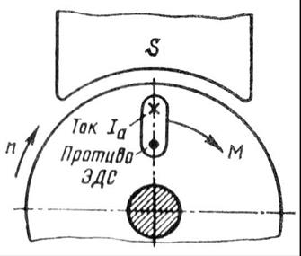
Collector machines have the property of reversibility, i.e. they can operate both in generator mode and in engine mode. Therefore, if a DC machine is connected to a DC power source, then currents will appear in the excitation winding and in the armature winding of the machine. The interaction of the armature current with the excitation field creates an electromagnetic moment on the armature M, which is not braking, as was the case in the generator, but rotating.
Under the influence electromagnetic moment armature, the machine will begin to rotate, i.e. the machine will operate in engine mode, consuming electrical energy from the network and converting it into mechanical energy. During the operation of the engine, its armature rotates in a magnetic field. An EMF is induced in the armature winding, the direction of which can be determined by the "right hand" rule. By its nature, it does not differ from the EMF induced in the generator armature winding. In the motor, the EMF is directed against the current, and therefore it is called antielectromotive force (back-EMF) of the armature (Fig. 29.1).
For an engine running at a constant speed,
![]() .
(29.1)
.
(29.1)
From (29.1) it follows that the voltage supplied to the motor is balanced by the back EMF of the armature winding and the voltage drop in the armature circuit. Based on (29.1) armature current
Multiplying both sides of equation (29.1) by armature current , we get power equation for armature circuit:
![]() , (29.3)
, (29.3)
where is the power in the armature winding circuit; - power of electrical losses in the armature circuit.
To clarify the essence of the expression, we will perform the following transformation:
![]() ,
,
![]() .
.
But, according to (25.24),
![]()
![]() , (29.4)
, (29.4)
where is the angular frequency of rotation of the armature; - electromagnetic power of the engine.
Therefore, the expression is electromagnetic power of the motor.
Transforming expression (29.3) taking into account (29.4), we obtain
![]() .
.
An analysis of this equation shows that with an increase in the load on the motor shaft, i.e. with an increase in the electromagnetic torque M, increases the power in the armature winding circuit, i.e., the power at the motor input. But since the voltage supplied to the motor is maintained unchanged, the increase in motor load is accompanied by an increase in current in the armature winding .
Depending on the method of excitation, DC motors, as well as generators, are divided into motors with excitation from permanent magnets (magnetoelectric) and with electromagnetic excitation. The latter, in accordance with the scheme for switching on the excitation winding relative to the armature winding, are divided into parallel (shunt), series (serial) and mixed (compound) excitation motors.
According to the EMF formula, motor speed (rpm)
Substituting the value from (29.1), we get (rpm)
i.e. the motor speed is directly proportional to the voltage and inversely proportional to the excitation flux. Physically, this is explained by the fact that the increase in voltage U or decrease in flow F causes an increase in the difference ; this, in turn, leads to an increase in current [see Fig. (29.2)]. As a result, the increased current increases the torque, and if the load torque remains unchanged, the motor speed increases.
From (29.5) it follows that the engine speed can be controlled by changing either the voltage u, supplied to the motor, or the main magnetic flux F, or electrical resistance in the armature circuit.
The direction of rotation of the armature depends on the directions of the magnetic flux of excitation F and current in the armature winding. Therefore, by changing the direction of any of these quantities, you can change the direction of rotation of the armature. It should be borne in mind that switching the common terminals of the circuit at the knife switch does not change the direction of rotation of the armature, since this simultaneously changes the direction of the current in both the armature winding and the excitation winding.
Engine start
The motor armature current is determined by formula (29.2). If accept U and unchanged, then the current depends on the back-EMF . The current reaches its maximum value when the engine is started. At the initial moment of starting, the motor armature is stationary and no EMF is induced in its winding. Therefore, when the motor is directly connected to the network, an inrush current occurs in the winding of its armature
Typically, the resistance is small, so the value of the starting current reaches unacceptably large values, 10-20 times higher than rated current engine.
Such a large starting current is very dangerous for the motor. Firstly, it can cause an all-round fire in the machine, and secondly, with such a current, an excessively large starting torque develops in the motor, which has a shock effect on the rotating parts of the motor and can mechanically destroy them. And finally, this current causes a sharp drop in voltage in the network, which adversely affects the operation of other consumers included in this network. Therefore, starting the engine by direct connection to the network (non-rheostatic start) is usually used for engines with a power of not more than 0.7-1.0 kW. In these motors, due to the increased resistance of the armature winding and small rotating masses, the starting current value is only 3-5 times higher than the rated current, which does not pose a danger to the motor. As for motors of greater power, when starting them, they use to limit the starting current. starting rheostats(PR), included in series in the armature circuit (rheostatic start).
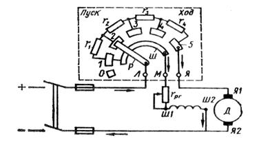
Before starting the engine, you need a lever R put the rheostat on idle contact O(Fig. 29.2). Then turn on the knife switch, move the lever to the first intermediate contact 1
and the motor armature circuit is connected to the network through the highest resistance of the rheostat ![]() .
.
Rice. 29.2. Scheme of switching on the starting rheostat
At the same time through the lever R and tire W an excitation winding is connected to the network, the current in which during the entire start-up period does not depend on the position of the lever R, since the resistance of the bus is negligible compared to the resistance of the excitation winding.
Starting armature current at the impedance of the starting rheostat
With the advent of current in the armature circuit, a starting torque occurs, under the influence of which the rotation of the armature begins. As the speed increases, the back-emf increases , which leads to a decrease in starting current and starting torque.
As the engine armature accelerates, the starting rheostat lever is switched to positions 2, 3, etc. In position 5 of the rheostat lever, the engine start ends. The resistance of the starting rheostat is usually chosen so that the maximum starting current exceeds the rated current by no more than 2-3 times.
Since the motor torque M directly proportional to flow F[cm. (25.24)], then to facilitate the start of the engine of parallel and mixed excitation, the resistance of the rheostat in the excitation circuit should be completely removed. excitation flow F in this case gets highest value and the motor develops the required torque at a lower armature current.
It is not advisable to use starting rheostats to start motors of greater power, as this would cause significant energy losses. Also, starting rheostats would be bulky. Therefore, in high-power engines, a rheostatless start of the engine is used by lowering the voltage. Examples of this are starting the traction motors of an electric locomotive by switching them from serial connection when starting in parallel with normal operation(see § 29.6) or starting the engine in a generator-motor circuit (see § 29.4).
Parallel excitation motor
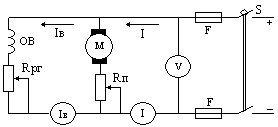
The scheme for connecting a parallel excitation motor to the network is shown in fig. 29.3, a. A characteristic feature of this motor is that the current in the field winding (OB) does not depend on the load current (armature current). The rheostat in the excitation circuit serves to regulate the current in the excitation winding and the magnetic flux of the main poles.
The performance properties of an engine are determined by its operating characteristics, which is understood as the dependence of the rotational speed n, current I, useful moment M2, torque M from the power on the motor shaft R 2 at and (Fig. 29.3, 6 ).
To analyze the dependence and , which is usually called the speed characteristic, we turn to formula (29.5), from which it can be seen that with a constant voltage U two factors affect the speed: the voltage drop in the armature circuit and the excitation flux F. With an increase in load, the numerator decreases, while due to the armature reaction, the denominator also decreases F. Typically, the reduction in flow caused by armature reaction is small and the first factor affects the speed more than the second. As a result, the engine speed with increasing load R 2 decreases, and the graph takes on a falling shape with a slight bulge facing the x-axis. If the reaction of the armature in the engine is accompanied by a more significant weakening of the flow F, then the rotational speed will increase with increasing load, as shown by the dashed curve in Fig. 29.3, b. However, such a dependence is undesirable, since, as a rule, it does not satisfy the condition for stable operation of the engine: with an increase in the load on the engine, the rotational speed increases, which leads to an additional increase in load, etc., i.e., the rotational speed n the engine increases indefinitely and the engine goes “overheated”. In order to give the speed characteristic a falling curve shape, some shunt motors use a light (with a small number of turns) series excitation winding, which is called stabilizing winding. When this winding is turned on in coordination with the parallel excitation winding, its MMF compensates for the demagnetizing effect of the armature reaction so that the flux F remains practically unchanged over the entire load range .., since
If we neglect the anchor reaction, then (since ) we can accept . Then the mechanical characteristic of the parallel excitation motor is a straight line, somewhat inclined to the abscissa axis (Fig. 29.4, a). The angle of inclination of the mechanical characteristic is the greater, the greater the value of the resistance included in the armature circuit. The mechanical characteristic of the engine in the absence of additional resistance in the armature circuit is called natural(straight 1 ). The mechanical characteristics of the engine, obtained by introducing additional resistance into the armature circuit, are called artificial(direct 2 and 3 ).
The type of mechanical characteristic also depends on the value of the main magnetic flux F. So, when decreasing F the speed of rotation x.x increases. and simultaneously increases, i.e., both terms of equation (29.11) increase. This leads to a sharp increase in the slope of the mechanical characteristic, i.e., to a decrease in its rigidity (Fig. 29.4, b).
When the armature voltage changes U rotational speed changes, but remains unchanged. As a result, the rigidity of the mechanical characteristic (if we neglect the influence of the armature reaction) does not change (Fig. 29.4, in), i.e., the characteristics shift in height while remaining parallel to each other.
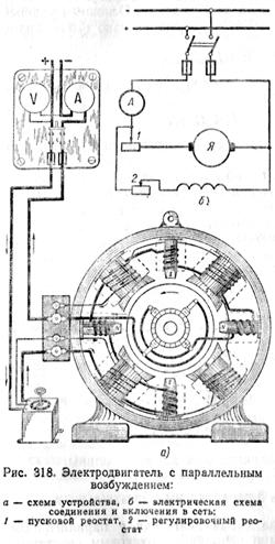
§ 138. ELECTRIC MOTOR WITH PARALLEL EXCITATION
On fig. 318 shows a diagram of a motor with parallel excitation and a starting rheostat included in the armature circuit. Since the excitation winding is connected in parallel to the network, then when constant resistance the excitation circuit and the mains voltage, the magnetic flux F of the motor must be constant.
From the formula
it can be seen that the value of counter-e. d.s. motor decreases with increasing armature current, causing the motor speed to also decrease.
However, as mentioned earlier, the magnitude of the voltage drop in the armature winding I a r a is very small compared to the voltage U. Therefore, with an increase in the load current, the engine speed decreases slightly.
Hence, a characteristic property of a motor with parallel excitation is an almost constant rotation speed when the load on its shaft changes. Usually, the speeds of engines of this type decrease by only 3-5% when full load is reached.
The torque of the motor is proportional to the product of the armature current and the magnetic flux:
From this it can be seen that the torque of the motor with parallel excitation is proportional to the armature current:
Therefore, by the ammeter included in the armature circuit, one can judge the engine load.
The engine will have the highest rotational speed at idle, if the resistance of the adjusting rheostat is completely removed. Opening the excitation circuit will cause the motor magnetic flux to decrease to a negligible amount of residual magnetism flux. Since counter-e. d.s. should be almost equal to the mains voltage, then with a decrease in the magnetic flux, the motor rotation speed will increase sharply and become dangerous for the mechanical strength of the motor. Therefore, when operating the engine, it is necessary to monitor the good condition of the excitation circuit.
Speed control of a shunt motor is usually done by varying the flux with a variable rheostat in the excitation circuit. This speed control method is the most economical. Some motors have speed control ranging from 1.5:1 to 4:1. The numbers show the ratio of the maximum speed to the minimum. The limits of regulation are limited mainly by the deterioration of switching conditions and the mechanical strength of the armature.
Changing the direction of rotation of motors with parallel excitation can be done by changing the direction of the current in the excitation winding of the poles or by changing the direction of the current in the armature winding. Usually, the change of rotation is carried out in the second way, since any operations with the excitation winding are dangerous for the operating personnel and undesirable due to the appearance of e. d.s. self-induction, which can cause breakdown of the winding insulation and burning of the contacts.
Motors with parallel excitation are used in DC networks to drive some machines, mechanisms (overhead electric roads, pumps, fans, weaving machines, rolling mills, mine hoists) that require a constant speed of rotation or wide speed adjustment.
23 .Anchor reaction, its Negative influence on the operation of a DC motor, ways to compensate for the armature reaction.
Armature reaction - the effect of the magnetic field created by the armature current on the magnetic field of the main poles of the machine. In idle mode, the armature current = 0 and the magnetic field of the machine is formed only by the main poles (Fig (a)). It is symmetrical about the axis of the main poles and about the geometric neutral. If you turn off the excitation winding and connect the armature to power supply, then the current flowing in the armature winding will create a magnetic field shown in Figure (b). Mag. the axis of the poles of this field coincides with the axis of the brushes and is perpendicular to the axis of the field of the main poles. The rotation of the armature does not affect the pattern of the armature field, because the current distribution in the armature winding remains constant. In the operating mode of the machine, both windings are turned on and the magnetic field is formed by summing both fields. As a result, the axis of the magnetic field is rotated by some angles, the physical neutral is rotated by the same angle. In motor mode, the neutral is shifted against rotation. As a result of the displacement, part of the conductors of the parallel branch located between the brush and the neutral will be under the pole of opposite polarity and will create a braking torque. A change in the load of the machine will lead to a change in the armature current and a corresponding increase or decrease in its magnetic field. Therefore, the angle will change with the load. In addition to neutral displacement, the armature reaction reduces the overall magnetic flux due to the fact that the field under the main poles is distorted. Under one edge of the pole, it is weakened, and under the other, it is strengthened, but the field amplification as a result of saturation of the pole edge is less than the weakening and the resulting magnetic flux decreases, which negatively affects the energy performance of the machine. The displacement of the physical neutral also has a negative effect on the switching process. The most effective . means of reducing the influence of the anchor reaction is compensation winding. It fits into the special grooves of the main poles and is connected in series to the armature circuit. The magnetic field of the compensation winding is opposite and compensates the magnetic field of the armature. Compensation winding current = armature current, so compensation occurs in all modes from idle to full load. As a result, the field of the machine under the main poles remains practically unchanged. Another way - increase clearance between the edges of the main poles and the anchor. To maintain the flow with an increase in the gap, an increase in the MMF of the excitation winding is required.
DC electrical machines.
Generator with parallel excitation.
Calculation formulas:
The current given by the generator to the network:
Eds. generator: E \u003d U + Iya ∙Rya.
Power delivered to the network: P2 \u003d U ∙ I \u003d I 2 ∙ R
Drive motor power: P1 = P2/ η
Power loss in the armature winding:
Rya \u003d I 2 i ∙ Rya
Power loss in the field winding:
Рв = U ∙Iв = I 2 в∙ Rв
Total losses: ΣP = P1 - ...
R2.
Generator efficiency:
η = Р2/Р1 = U∙I / (U∙I+ ΣР)
Motor with parallel excitation.
Calculation formulas:
Motor current: I \u003d Ia + Iv
Engine voltage: U \u003d E + Ii ∙Rya.
Power consumed from the network: Р1 = U∙I
Shaft power: P 2 = P 1 ∙η
Moment on the motor shaft:
M \u003d 9550 ∙ P 2 / n 2.
Engine efficiency:
η \u003d P 2 / P 1 \u003d (U∙I-ΣP) / U∙I
Example 6.1. A DC generator with parallel excitation develops a rated voltage Un = 220 V. The generator is loaded with a load Rn = 2.2 Ohm. Armature winding resistance Rya = 0.2 Ohm, excitation winding Rv = 220 Ohm. Generator efficiency η = 0.87. Determine the following quantities:
1.load current; 2. armature current; 3. excitation current; 4. generator emf;
5.net power; 6. power consumption; 7. total losses in the generator; 8. losses in the armature winding; 9. losses in the excitation winding.
1.Load current:
2. Excitation current:
![]()
3. Armature current: Iа \u003d I - Iv \u003d 100 - 1 \u003d 99 A.
4. Emf generator:
E \u003d U + Ii ∙ Rya \u003d 220 + 99 0.1 \u003d 229.9 V.
5.Net power:
Р2 = Un ∙ I = 220 ∙ 100 = 22000 W = 22 kW.
6.Power consumption:
7. Total losses in the generator:
ΣP \u003d P1 - P2 \u003d 25.87 - 22 \u003d 3.87 kW.
8.Losses in the armature winding:
Rya \u003d Iya 2 ∙Rya \u003d 99 2 ∙0.2 \u003d 1960.2 W.
9. Losses in the excitation winding:
Pv = Un ∙ Iv = 220 ∙ 1 = 220 W.
Answer: I = 100A; Iv \u003d 1 A; Ia = 99 A; E = 229.9 V; P2 = 22 kW;
P1 = 25.87 kW; ΣР = 3.87 kW; Rya = 1960.2 W; Pv \u003d 220 W.
Example 6.2. Fig. 8.2. A DC motor of parallel excitation operates from the network Un = 220 V. Armature speed n2 = 1450 rpm. Motor current I \u003d 500 A, armature back emf E \u003d 202 V, excitation winding resistance Rv \u003d 44 Ohms. Engine efficiency
η = 0.88. Determine: 1. excitation current; 2. armature current; 3. armature winding resistance; 4.power consumption; 5.useful shaft power; 6 Total losses in the motor; 7. losses in the armature winding; 8. losses in the armature winding; 9.torque on the shaft.
1. Excitation current:
![]()
2. Armature current:
Ia \u003d I - Iv \u003d 500 -5 \u003d 495 A.
3. Armature winding resistance:
4. Power consumption from the network:
P1 \u003d Un ∙ I \u003d 220 ∙ 500 \u003d 110,000 W \u003d 110 kW.
5. Net shaft power:
Р2 = P1 ∙ η = 110 ∙ 0.87 = 95.7 kW.
6. Total losses in the motor:
ΣP \u003d P1 - P2 \u003d 110 - 95.7 \u003d 14.3 kW.
We advise you to read
, diagnosis, treatment Treatment of urogenital chlamydia") Urogenital chlamydia - description, causes, symptoms (signs), diagnosis, treatment Treatment of urogenital chlamydia
Urogenital chlamydia - description, causes, symptoms (signs), diagnosis, treatment Treatment of urogenital chlamydia The benefits and significance of hydroamino acid threonine for the human body L threonine what
 To wait or not to wait for a guy from the army For what reason can they be commissioned from the army
 Baked apples with cottage cheese Baked apples with cottage cheese

