For everybody induction motor the nominal mode can be defined, i.e. the mode of long-term operation, in which the engine does not overheat above the set temperature. The moment M rated, corresponding to the nominal mode, is called. nominal moment. The corresponding rated slip for asynchronous motors of medium power is s H0M = 0.02 ... 0.06, i.e. rated speed n and ohm is within
n nom = n 0 (1 - s 0) \u003d (0.94 ... 0.98) p 0
The ratio of the maximum torque to the nominal to m = = Mmax / M nom is called the overload capacity of the asynchronous motor. Usually k m \u003d 1.8 ... .2.5.
When starting up, i.e. when starting off and during acceleration, the asynchronous motor is in conditions that are significantly different from the conditions of normal operation. The torque developed by the motor must exceed the moment of resistance of the load, otherwise the motor will not be able to accelerate. Thus, from the point of view of starting the engine, its starting torque plays an important role.
The ratio of the starting torque M p developed by the engine in a stationary state, i.e., at n \u003d 0, to the rated torque k p \u003d M p / M nom is called the multiplicity of the starting torque.
The maximum moment M max is called the critical moment of the asynchronous machine. The operation of the machine with a torque exceeding the rated one is possible only for a short time, otherwise the service life of the machine is reduced due to its overheating.
As a result of the interaction of a rotating magnetic flux with the currents induced by it in the conductors of the rotor winding, forces arise that act on these conductors in the tangential direction. Let us find the value of the moment created by these forces on the shaft of the machine.
The electromagnetic power transmitted to the rotor by the rotating magnetic field is equal to:
where M uh - electromagnetic moment acting on the rotor.
According to the equivalent circuit of one phase of the machine:
From these expressions we find:
Given the current rotor current, EMF, inductive reactance we get:
We introduce a constant and neglecting the moment of friction, we represent the expression for the moment on the shaft in the form:
If the magnetic flux Ф is expressed in webers, the current I 2 - in amperes, then the torque will be in newton meters (Nm).
The torque of the machine depends on the load f, I 2 and , but it can be represented as a function of one variable. As such a variable for an induction motor, it is most convenient to choose the slip s.
According to the previously studied formulas:
Assuming that the network frequency is unchanged, we introduce
36. Methods for regulating the speed of rotation hell with short circuit. rotor
37.Start and control the speed of rotation of blood pressure with f.r.
Regulation by changing the slip is performed by changing the resistance R p of the adjusting rheostat in the rotor circuit.
The introduction of a rheostat into the rotor circuit changes the dependence of the torque M on the slip s without affecting the magnitude of the maximum torque. Three characteristics M(s): natural (non-rheostat) characteristic 1 corresponds to a short-circuited rotor winding (rheostat resistance = 0), rheostatic (artificial) characteristics 2 and 3 correspond to the introduced one and two stages of the rheostat.
The introduction of a rheostat into the rotor circuit has a positive effect on the starting current, reducing it by about 2 times compared to a short-circuited IM.
The disadvantages of this method: 1) low efficiency due to losses in the rheostat R p ; 2) reduction in the rigidity of mechanical characteristics; 3) the speed can only be adjusted downwards.
Starting an asynchronous motor with a phase rotor. The start-up of asynchronous motors differs significantly from the conditions of normal operation. The motor torque at start-up must exceed the load resistance torque, the starting torque plays a role. The second important starting characteristic is the starting current. Starting current ratio for motors with squirrel-cage rotor reaches 5-7, which may be unacceptable for the motor or for the network, and may make a difference in the smoothness of the start. The start-up of a motor with a phase rotor is carried out through a 3-phase rheostat, each phase of which is connected through brushes and rings to one of the phases of the rotor. At the beginning of the start, the rheostat is fully inserted, by the end of the start it is removed and all three phases of the rotor are short-circuited. The number of rheostat steps is taken to be more than two, and the switching process at start-up is usually automated. The introduction of active resistances in the phase rotor circuit increases the torque and makes the start smooth and limits the starting current. This starting method has a number of advantages, but is applicable only for motors with a phase rotor.
39.40. Device, principle of operation of the engine direct current. Excitation methods. EMF of the armature winding and electromagnetic torque Design and principle of operation of a DC motor A DC motor consists of a fixed part - the stator and a rotating part - the armature, separated by an air gap. The main additional poles are attached to the inner surface of the stator. The main poles with excitation windings serve to create the main magnetic flux F in the machine, and the additional ones to reduce sparking.
The armature consists of a shaft, a core, a winding and a collector. The collector contains copper plates isolated from each other, which are connected to the sections of the armature winding. Fixed brushes are superimposed on the collector; connecting the armature winding with an external electrical circuit. As a result of the interaction of the armature current Iya And the magnetic flux Ф, a torque is created, M = CmFIa, where Cm is the moment constant, which depends on the design data of the machine. The torque M of the engine is balanced by the moment of resistance Ms of the working machine. When the armature rotates with a frequency n, its winding crosses the magnetic flux Ф and in it, according to the law of electromagnetic induction, a counter-EMF is induced E \u003d CeFp, where Ce is a constructive constant.
The voltage at the armature ezhimax U is equal to the sum of the EMF and the voltage drop across the resistance of the anchor circuit U=E +RyaIya=CeFn, whence the armature current Ia=(U-CeFn)/Rya, and the speed n=(U-RyaIya)/CeF/
Depending on the method of supplying the excitation winding, DC generators are:
| a B C D) |
Rice. 50. Generator excitation: a - independent, b - parallel, c - serial, d - mixed.
At independent arousal OB is powered by an external source. It is used in cases where it is necessary to regulate the excitation current I in and the voltage U at the clamps of the machine over a wide range. The armature current is equal to the load current I I \u003d I n (Fig. 50, a)
Self-excited generators have OBs powered by the generator itself.
When the OB is turned on in parallel with the armature winding, we have a generator with parallel excitation(Fig. 50, b), in which I I \u003d I n + I c. For powerful machines of normal execution, I in is usually 1-3%, and for small machines - up to several tens of% of the armature current. For a generator with serial excitation (Fig. 50, c), the ORP is connected in series with the armature, i.e.
I i \u003d I n \u003d I c.
Generators with mixed excitation have two excitation windings, the OB is connected in parallel with the armature, and the other ORP is in series (Fig. 50, d). The main one is usually OB. ORP magnetizes the machine with an increase in load current, which compensates for the voltage drop U in the armature winding and the demagnetizing effect of the armature reaction.
The voltage U 1 applied to the phase of the stator winding is balanced by the main EMF E 1, the leakage EMF and the voltage drop across the active resistance of the stator winding:
In a rotor winding, a similar equation will look like:
But since the rotor winding is closed, the voltage U 2 \u003d 0, and if we also take into account that E 2s \u003d SE 2 and x 2s \u003d Sx 2, then the equation can be rewritten as:
![]()
The equation for the currents of an induction motor repeats a similar equation for a transformer:
28 Asynchronous motor torque
The torque in an induction motor is created by the interaction of the rotor current with the magnetic field of the machine. The torque can be mathematically expressed in terms of the electromagnetic power of the machine:
where w 1 =2pn 1 /60 - angular frequency of rotation of the field. In its turn, n 1 =f 1 60/R, then
![]()
Substitute in the formula M 1 expression REm=Pe2/S and, dividing by 9.81, we get:
![]()
Induction Motor Torque Equation
It follows that the motor torque is proportional to the electrical losses in the rotor. Substitute in the last formula the current value I 2 ’ :
we obtain the equation for the torque of an induction motor:
where U 1 - phase voltage of the stator winding.
29 .Motor mechanical characteristic is called the dependence of the rotor speed on the torque on the shaft n = f (M2). Since the idle torque is small under load, then M2 ≈ M and mechanical characteristic is represented by the dependence n = f (M). If we take into account the relationship s = (n1 - n) / n1, then the mechanical characteristic can be obtained by presenting its graphical dependence in the coordinates n and M (Fig. 1).
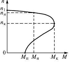
Rice. 1. Mechanical characteristic of asynchronous motor
Natural mechanical characteristic of an induction motor corresponds to the main (passport) circuit of its inclusion and the nominal parameters of the supply voltage. Artificial characteristics are obtained if any additional elements are included: resistors, reactors, capacitors. When the motor is supplied with a non-rated voltage, the characteristics also differ from the natural mechanical characteristic.
The mechanical characteristics are very convenient and useful tool in the analysis of static and dynamic modes of the electric drive.
30 Mechanical characteristic and motor self-regulation. The graph linking mechanical quantities - speed and torque - is called the mechanical characteristic of an induction motor (Fig. 7) n = ƒ(M). Self-regulation of an asynchronous motor is as follows. Let the engine work steadily in some mode, developing speed n1 and torque M1. With uniform rotation, this moment is equal to the braking torque M t1, i.e. M1=M t 1, n1= conset. Increasing the braking torque to M2 will cause a decrease in machine speed, since the braking torque will become greater than the torque. With a decrease in speed, the slip increases, which in turn causes an increase in the EMF and current in the rotor. This increases the engine torque. This process ends when the torque M2 developed by the engine becomes equal to M t 2. In this case, the rotation speed is set lower than n1. The property of automatic equilibrium between braking and torque is called self-regulation.
On a laboratory stand, the engine is loaded with an electric brake, consisting of an electromagnet, in the gap of which a disc rotates, planted on the engine shaft. By changing the voltage supplying the electromagnet coil with the handle of the autotransformer, it is possible to change the braking force, the moment of which is: M TORM \u003d F r (N m)
where F is the force (force) acting on the circumference of the pulley, (N);
r - pulley radius, equal to 0.18 m. Useful power on the motor shaft:
where n- engine rotation speed, rpm.
where ƒ - network frequency (equal to 50 Hz),
R- number of pairs of poles of the stator winding (equal to 2).
n 1 - synchronous speed of the rotating magnetic field.
The engine speed is determined using a tachometer. Slip is calculated by the formula:
31 Operating characteristics called power dependencies, consumed by the motor, consumed current I, power factor, motor speed, efficiency and torque M from the useful power of the motor given to the shaft. Performance characteristics determine the basic performance properties of an induction motor. The performance characteristics of a medium power induction motor are shown in fig. 8.8. Their behavior is explained as follows. At light loads, the motor current I (no-load current) can be between 20% and 70% of the rated current. As the load increases, the current in the rotor circuit increases, which leads to an almost proportional increase in current I in the stator circuit.

Fig.8.8 Motor torque () is also almost proportional to the load, but at high loads, the linearity of the graph is somewhat violated by reducing the engine speed. The performance characteristic expresses the relationship between the power developed by the motor and the phase shift between the stator current and voltage. An asynchronous motor, like a transformer, consumes a current I from the network, which is significantly out of phase with the applied voltage. For example, in idle mode. With an increase in the load on the motor shaft, the active components of the rotor and stator currents increase, increasing . The maximum value is reached at .
With a further increase, the value will decrease slightly. This is due to an increase in slip s, which causes an increase in the reactance of the rotor winding, and, consequently, the phase shift . FROM increases and increases, i.e. will decrease.
Behavior operating characteristic is explained as follows. The value of efficiency is determined by the ratio of useful power to the power consumed from the network.
The value is called the power loss. In addition to losses in the steel of the stator and rotor due to magnetization reversal and eddy currents, which, together with mechanical losses, can be considered constant, there are losses in copper in an asynchronous motor. ,
those. in the stator and rotor windings, which are proportional to the square of the current flowing and therefore dependent on the load. During idling, as in a transformer, losses in steel predominate, since, and is equal to the no-load current, which is small. With small loads on the shaft, the losses in copper still remain small, and therefore the efficiency determined by the formula ![]() (8.5)
(8.5)
increases sharply at first. When the fixed losses become equal to the load-dependent losses , efficiency reaches its maximum value. With a further increase in the load, the variable power losses increase significantly, as a result of which the efficiency noticeably decreases. The nature of addiction ) can be explained from the relation . If the efficiency was constant, then there would be a linear relationship between and. But since the efficiency depends on and this dependence initially increases sharply, and with a further increase in the load changes slightly, then the curve ) first increases slowly, and then increases sharply.
32 At any electrical circuit the sum of the powers of all sources of electrical energy must be equal to the sum of the powers of all receivers and auxiliary elements. Having previously obtained the power expressions, it is possible to write in a general form the power balance equation for any electrical circuit:
Σ E → I → + Σ U ← I → = Σ E ← I → + Σ U → I → + Σ I 2 r.
Equation (1.35) can be written both for the real EMF directions, voltages and currents, and for the case when some of them are arbitrarily chosen positive directions. In the first case, all terms in it will be positive and the corresponding elements of the circuit will actually be sources or receivers of electrical energy. If, on the other hand, some terms are written with respect to arbitrarily chosen positive directions, the corresponding elements must be considered as intended sources and receivers. As a result of calculation or analysis, some of them may turn out to be negative. This will mean that some of the supposed sources is actually a sink, and some of the supposed sinks is a source.
33 Starting an asynchronous motor is accompanied by a transient process of the machine associated with the transition of the rotor from a state of rest to a state of uniform rotation, in which the engine torque balances the moment of resistance forces on the machine shaft. When starting an asynchronous motor, there is an increased consumption of electrical energy from the supply network, which is spent not only on overcoming the braking torque applied to the shaft and covering losses in the asynchronous motor itself, but also on communicating a certain kinetic energy to the moving parts of the production unit. Therefore, when starting, an asynchronous motor must develop an increased torque. For asynchronous motor with a phase rotor the initial starting torque, corresponding to the slip sp = 1, depends on the active resistances of the adjustable resistors introduced into the rotor circuit.
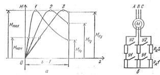
Rice. 1. Starting a three-phase asynchronous motor with a phase rotor: a - graphs of the dependence of the torque of the motor with a phase rotor on slip at various active resistances of the resistors in the rotor circuit, b - diagram of the inclusion of resistors and acceleration closing contacts in the rotor circuit. So, with closed acceleration contacts U1, U2, i.e. when starting an asynchronous motor with shorted contact rings, the initial starting torque Mp1 = (0.5 -1.0) Mnom, and the initial starting current Ip = (4.5 - 7) Inom and more. Small starting torque asynchronous motor with a wound rotor may not be enough to drive the production unit and then accelerate it, and a significant starting current will cause increased heating motor windings, which limits the frequency of its switching on, and in low-power networks leads to a temporary voltage drop that is undesirable for the operation of other receivers. These circumstances may be the reason that excludes the use of asynchronous motors with a phase rotor with a large starting current to drive working mechanisms. The introduction of adjustable resistors, called starting resistors, into the motor rotor circuit not only reduces the initial starting current, but at the same time increases the initial starting torque, which can reach the maximum torque Mmax (Fig. 1, a, curve 3), if the critical slip of the motor with a phase rotor scr \u003d (R2 "+ Rd") / (X1 + X2") \u003d 1, where Rd" is the active resistance of the resistor located in the phase of the motor rotor winding, reduced to the phase of the stator winding. A further increase in the active resistance of the starting resistor is impractical, since it leads to a weakening of the initial starting torque and the exit of the maximum torque point into the slip region s > 1, which excludes the possibility of rotor acceleration. The required active resistance of the resistors for starting a motor with a phase rotor is determined based on the requirements of the start, which can be easy when Mp = (0.1 - 0.4) Mnom, normal if Mp - (0.5 - 0.75) Mnom, and heavy at Mp ≥ Mnom. In order to maintain a sufficiently large torque by the motor with a phase rotor during the acceleration of the production unit in order to reduce the duration of the transient process and reduce the heating of the motor, it is necessary to gradually reduce the active resistance of the starting resistors. The allowable torque change during acceleration M(t) is determined by the electrical and mechanical conditions that limit the peak torque limit M > 0.85 Mmax, the switching torque M2 > > Ms (Fig. 2), as well as acceleration.

Rice. 2. Starting characteristics of a three-phase asynchronous motor with a phase rotor. Switching of starting resistors is provided by successive switching on of acceleration contactors Y1, Y2, respectively, at time points t1, t2 counted from the moment of starting the engine, when during acceleration the torque M becomes equal to the switching moment M2. Due to this, during the entire start-up, all peak torques are the same and all switching torques are equal to each other. Since the torque and current of an asynchronous motor with a phase rotor are mutually related, it is possible to set the peak current limit I1 \u003d (1.5 - 2.5) Inom and the switching current I2 during the acceleration of the rotor, which should provide the switching moment M2\u003e Mc. Disconnection of asynchronous motors with a phase rotor from the supply network is always performed with the rotor circuit short-circuited, in order to avoid overvoltages in the phases of the stator winding, which can exceed the rated voltage of these phases by 3-4 times, if the rotor circuit at the moment the engine is turned off is open.
34 Frequency regulation. This method of speed control allows the use of the most reliable and cheapest asynchronous motors with a squirrel-cage rotor. However, to change the frequency of the supply voltage, a variable frequency electric current source is required. As the latter, either synchronous generators with a variable speed are used, or frequency converters - electric or static, made on controlled semiconductor valves (thyristors). Currently, frequency converters have a rather complex circuit and a relatively high cost. However, the rapid development of power semiconductor technology allows us to hope for further improvement of frequency converters, which opens up prospects for wide application frequency regulation. A detailed description of the control laws for frequency regulation and an analysis of the operation of an asynchronous motor when powered by a frequency converter are given in § 4.13 and 4.14. Regulation by changing the number of poles. This regulation allows you to get a step change in speed. On fig. 4.35 shown the simplest circuit(for one phase), which allows you to change the number of poles of the stator winding twice. To do this, each phase of the stator winding is divided into two parts, which are switched from series connection to parallel. It can be seen from the figure that when coils 1-2 and 3-4 are turned on in two parallel branches, the number of poles is halved, and, consequently, the frequency of rotation of the magnetic field is doubled. When switching, the number of series-connected turns in each phase is halved, but since the rotational speed doubles, the EMF induced in the phase remains unchanged. Therefore, the motor at both speeds can be connected to the network with the same voltage. In order not to switch in the rotor winding, the latter is performed short-circuited. If you need to have three or four speeds, then another winding is placed on the stator, by switching which you can get an additional two frequencies. Pole-changing induction motors are called multi-speed. Regulation by including a rheostat in the rotor circuit. When additional active resistances are included in the rotor circuit R ext1 , R ext2 , R add3 and others changes the form of dependency M = f(s) and mechanical characteristics n 2 = f(M) engine (Fig. 4.37, a). At the same time, some load moment M n match slip s 1 , s 2 , s 3 , ..., larger than slips s e , when the engine is running on a natural characteristic (when R ext = 0). Therefore, the steady-state engine speed decreases from n e before P 1 P 2 , P 3 ,... (Fig. 4.37, b). This control method can only be used for slip-ring motors. It allows you to smoothly change the speed over a wide range. Its disadvantages are: a) large energy losses in the control rheostat; b) excessively "soft" mechanical characteristics of the engine with high resistance in the rotor circuit. In some cases, the latter is unacceptable, since a small change in the load torque corresponds to a significant change in the speed.
35 Asynchronous generator- this is an asynchronous electric machine (el. engine) operating in the generator mode. With the help of a drive motor (in our case, a wind turbine), the rotor of an asynchronous electric generator rotates in the same direction as the magnetic field. In this case, the slip of the rotor becomes negative, a braking torque appears on the shaft of the asynchronous machine, and the generator transfers energy to the network. For arousal electromotive force its output circuit uses the residual magnetization of the rotor. For this, capacitors are used. Asynchronous generators are not susceptible to short circuits. An asynchronous generator is simpler than a synchronous one (for example, car generator): if the latter has inductors placed on the rotor, then the rotor of the asynchronous generator looks like a conventional flywheel. Such a generator is better protected from dirt and moisture, more resistant to short circuit and overloads, and the output voltage of the asynchronous generator has a lower degree of non-linear distortion. This allows you to use asynchronous generators not only to power industrial devices that are not critical to the shape of the input voltage, but also to connect electronic equipment. It is an asynchronous electric generator that is an ideal current source for devices with an active (ohmic) load: electric heaters, welding converters, incandescent lamps, electronic devices, computer and radio engineering. Benefits of an asynchronous generator. These advantages include a low clear factor (harmonic coefficient), which characterizes the quantitative presence of higher harmonics in the output voltage of the generator. Higher harmonics cause uneven rotation and useless heating of electric motors. Synchronous generators can have a clear factor of up to 15%, and the clear factor of an asynchronous generator does not exceed 2%. Thus, an asynchronous electric generator produces practically only useful energy. Another advantage of an asynchronous generator is that it completely lacks rotating windings and electronic parts that are sensitive to external influences and are quite often prone to damage. That's why asynchronous generator little wear and can serve for a very long time. At the output of our generators, there is immediately 220/380V AC, which can be used directly to household appliances (for example, heaters), to charge batteries, to connect to a sawmill, and also for parallel operation with a traditional network. In this case, you will pay for the difference consumed from the network and generated by the windmill. Because Since the voltage comes immediately to industrial parameters, then you will not need various converters (inverters) when the wind generator is directly connected to your load. For example, you can connect directly to a sawmill and, in the presence of wind, work as if you were simply connected to a 380V network. As you know, to reduce the braking time when stopping production machines and mechanisms, mechanical brakes are often used. Reducing the braking time, especially in the case of a short cycle of work, leads to a significant increase in the productivity of machines and mechanisms. The disadvantages of mechanical brakes are the rapid wear of rubbing surfaces, the complexity and need for periodic regulation of the braking force, the need for additional space for placing the brake and its connection to the mechanism. All of the above disadvantages are eliminated if, for the indicated purposes, instead of a mechanical brake, the properties of electric motors are used to work in braking modes, that is, to work essentially as a generator and develop not a torque, but a braking torque. In many hoisting and transport machines (cranes, elevators, escalators, etc.), where movement under the action of gravity is possible, a constant, steady rate of lowering loads is ensured using the braking torque of the electric motor. DC motors can operate in three braking modes:
In opposition mode;
In generator mode with energy output to the network;
In mode dynamic braking.
In any of the braking modes, the electric motor works as a generator, converts, for example, the kinetic energy of moving parts or the potential energy of a descending load into electrical energy.
36 When the engine is reversed on the move by switching the switch, braking first occurs from a given speed to zero, and then acceleration in the other direction. Such braking can also be used for braking during the so-called opposition. During this reversal or braking, a squirrel-cage induction motor has significant currents. Therefore, based on the heating conditions for these engines, the number of reversals per hour is not more than tens. To limit currents and increase torques, resistance is introduced into the phase rotor circuit of an asynchronous motor. Let's consider three main ways of electric braking of asynchronous motors. Braking by way of opposition, as indicated, it is performed when the engine is switched on the go. In this case, the magnetic field rotates in the opposite direction relative to the direction of rotation of the motor, and the torque of the motor is braking - it acts against the direction of rotation. Generator braking takes place when switching a multi-speed engine on the move from a higher speed to a lower one, i.e. when switching the machine from a smaller number of poles to a larger one. At the first moment of switching, the engine speed turns out to be much greater than the speed of its field, i.e., the slip turns out to be negative and the machine switches to the generator mode. Braking occurs with the transformation of the kinetic energy of the rotating parts into electrical energy, which minus losses in the machine is given to the network. Generator braking can also be in the lift when lowering a heavy load, accelerating the engine to a speed exceeding synchronous; then the machine begins to give to the network the energy imparted to it by the descending load. Generator braking is only possible at oversynchronous speed. If the engine must be stopped at the end of braking, then by the end of braking it is necessary to switch to mechanical braking or to another type of electric braking (dynamic, counter-switching). Fixing the position at the end, if necessary, is carried out only with the help of a mechanical brake. At dynamic braking motor stator winding is disconnected from three-phase network and is included in the network of direct or single-phase alternating currents. In this case, various ways of connecting the phases of the stator winding are possible. The stator winding, powered by direct current, creates a stationary magnetic field. Just as during normal operation of the engine, its rotating field drags the rotor along with it, a stationary field during dynamic braking causes the rotor to stop quickly. Kinetic energy rotating parts is converted into heat released in the rotor circuit due to currents induced in it by the fixed stator field. The smoothness of braking is ensured by regulating the voltage at the stator terminals. The braking torque of the motor with a phase rotor can also be regulated by a rheostat in the rotor circuit. The disadvantage of dynamic braking is the need for a low voltage DC source.
37 Synchronous machine- this is an AC electric machine, the rotor speed of which is equal to the frequency of rotation of the magnetic field in the air gap. The main parts of a synchronous machine are the armature and the inductor. The most common design is one in which the armature is located on the stator, and there is an inductor on the rotor separated from it by an air gap. An armature is one or more AC windings. In motors, the currents supplied to the armature create a rotating magnetic field that couples with the field of the inductor, and thus the energy is converted. The armature field affects the field of the inductor and is therefore also called anchor reaction field. In generators, the anchor reaction field is created alternating currents induced in the armature winding from the inductor. The inductor consists of poles - DC electromagnets or permanent magnets (in micromachines). Synchronous machine inductors come in two different designs: salient pole or non-salient pole. A salient pole machine is distinguished by the fact that the poles are pronounced and have a design similar to the poles of a DC machine. With an implicit pole design, the excitation winding fits into the grooves of the inductor core, very similar to the winding of the rotors of asynchronous machines with a phase rotor, with the only difference being that a space is left between the poles that is not filled with conductors (the so-called big tooth). Non-salient pole designs are used in high-speed machines to reduce the mechanical load on the poles. To reduce the magnetic resistance, that is, to improve the passage of the magnetic flux, ferromagnetic cores of the rotor and stator are used. Basically, they are a laminated electrical steel structure (that is, assembled from separate sheets). Electrical steel has a number of interesting properties. In particular, it has a high silicon content in order to increase its electrical resistance and thereby reduce eddy currents.
The action of a magnetic field on a current-carrying coil makes it possible to use it to determine magnetic induction module. Turning a coil in a magnetic field indicates that at least two forces act on it. The resultant of these forces will be applied at points A and B (Fig. 6.8). Torque, acting on the coil, will be equal to the product of one of these forces F̅ to the radius of the turn r. This point does not need to be calculated. It can be measured using a coil spring or other sensitive device for measuring mechanical torque connected to the coil.
Experiments show that a coil with current in a magnetic field always rotates so that the direction of its normal n̅ coincides with the direction of the magnetic induction of the field under study B̅. Obviously, in this case, the torque will be zero. It will have a maximum value when the angle between the magnetic induction B̅ and normal n̅ will be 90°.
Magnetic induction can be determined by the force action of a magnetic field on a current with a current.
Without changing the current strength in the conductor, we investigate how the value depends maximum torque from the coil parameters.
Having placed the coil at a certain distance from the current-carrying conductor, we measure the maximum torque Mmax for a certain value of current in a coil I 1. Let's double the current in the coil. At I 2 = 2I 1 the maximum mechanical moment will be equal to M max 2 = 2M max 1. The same will be observed with an increase in current strength by 3, 4, 5 times. In this way, maximum torque value, which acts on the coil with current, will be proportional to the current in the coil
Mmax ~I vit.
Torque , acting on a coil in a magnetic field, is proportional to the strength of the current in it.material from the site
If we replace this coil with another, with a larger or smaller area S vit, we will notice a corresponding increase or decrease in the value of the maximum torque. In this way,
maximum torque , which acts on a coil in a magnetic field, is proportional to its area:
Mmax ~S vit.
Combining the results of both stages of research, we get
Mmax ~I vit.S vit.
On this page, material on the topics:
The voltage U 1 applied to the phase of the stator winding is balanced by the main EMF E 1, the leakage EMF and the voltage drop across the active resistance of the stator winding:
In a rotor winding, a similar equation will look like:
But since the rotor winding is closed, the voltage U 2 \u003d 0, and if we also take into account that E 2s \u003d SE 2 and x 2s \u003d Sx 2, then the equation can be rewritten as:
![]()
The equation for the currents of an induction motor repeats a similar equation for a transformer:
28 Asynchronous motor torque
The torque in an induction motor is created by the interaction of the rotor current with the magnetic field of the machine. The torque can be mathematically expressed in terms of the electromagnetic power of the machine:
where w 1 =2pn 1 /60 - angular frequency of rotation of the field. In its turn, n 1 =f 1 60/R, then
![]()
Substitute in the formula M 1 expression REm=Pe2/S and, dividing by 9.81, we get:
![]()
Induction Motor Torque Equation
It follows that the motor torque is proportional to the electrical losses in the rotor. Substitute in the last formula the current value I 2 ’ :
we obtain the equation for the torque of an induction motor:
where U 1 - phase voltage of the stator winding.
29 .Motor mechanical characteristic is called the dependence of the rotor speed on the torque on the shaft n = f (M2). Since the idle torque is small under load, then M2 ≈ M and the mechanical characteristic is represented by the dependence n = f (M). If we take into account the relationship s = (n1 - n) / n1, then the mechanical characteristic can be obtained by presenting its graphical dependence in the coordinates n and M (Fig. 1).
Rice. 1. Mechanical characteristic of asynchronous motor
Natural mechanical characteristic of an induction motor corresponds to the main (passport) circuit of its inclusion and the nominal parameters of the supply voltage. Artificial characteristics are obtained if any additional elements are included: resistors, reactors, capacitors. When the motor is supplied with a non-rated voltage, the characteristics also differ from the natural mechanical characteristic.
Mechanical characteristics are a very convenient and useful tool in the analysis of static and dynamic modes of the electric drive.
30 Mechanical characteristic and motor self-regulation. The graph linking mechanical quantities - speed and torque - is called the mechanical characteristic of an induction motor (Fig. 7) n = ƒ(M). Self-regulation of an asynchronous motor is as follows. Let the engine work steadily in some mode, developing speed n1 and torque M1. With uniform rotation, this moment is equal to the braking torque M t1, i.e. M1=M t 1, n1= conset. Increasing the braking torque to M2 will cause a decrease in machine speed, since the braking torque will become greater than the torque. With a decrease in speed, the slip increases, which in turn causes an increase in the EMF and current in the rotor. This increases the engine torque. This process ends when the torque M2 developed by the engine becomes equal to M t 2. In this case, the rotation speed is set lower than n1. The property of automatic equilibrium between braking and torque is called self-regulation.
On a laboratory stand, the engine is loaded with an electric brake, consisting of an electromagnet, in the gap of which a disc rotates, planted on the engine shaft. By changing the voltage supplying the electromagnet coil with the handle of the autotransformer, it is possible to change the braking force, the moment of which is: M TORM \u003d F r (N m)
where F is the force (force) acting on the circumference of the pulley, (N);
r - pulley radius, equal to 0.18 m. Useful power on the motor shaft:
where n- engine rotation speed, rpm.
where ƒ - network frequency (equal to 50 Hz),
R- number of pairs of poles of the stator winding (equal to 2).
n 1 - synchronous speed of the rotating magnetic field.
The engine speed is determined using a tachometer. Slip is calculated by the formula:
31 Operating characteristics they call the dependences of the power consumed by the engine, the consumed current I, power factor, engine speed, efficiency and torque M on the useful power of the engine given off on the shaft. Performance characteristics determine the basic performance properties of an induction motor. The performance characteristics of a medium power induction motor are shown in fig. 8.8. Their behavior is explained as follows. At light loads, the motor current I (no-load current) can be between 20% and 70% of the rated current. As the load increases, the current in the rotor circuit increases, which leads to an almost proportional increase in current I in the stator circuit.
Fig.8.8 Motor torque () is also almost proportional to the load, but at high loads, the linearity of the graph is somewhat violated by reducing the engine speed. The performance characteristic expresses the relationship between the power developed by the motor and the phase shift between the stator current and voltage. An asynchronous motor, like a transformer, consumes a current I from the network, which is significantly out of phase with the applied voltage. For example, in idle mode. With an increase in the load on the motor shaft, the active components of the rotor and stator currents increase, increasing . The maximum value is reached at .
With a further increase, the value will decrease slightly. This is due to an increase in slip s, which causes an increase in the reactance of the rotor winding, and, consequently, the phase shift . FROM increases and increases, i.e. will decrease.
The behavior of the operating characteristic is explained as follows. The value of efficiency is determined by the ratio of useful power to the power consumed from the network.
The value is called the power loss. In addition to losses in the steel of the stator and rotor due to magnetization reversal and eddy currents, which, together with mechanical losses, can be considered constant, there are losses in copper in an asynchronous motor. ,
those. in the stator and rotor windings, which are proportional to the square of the current flowing and therefore dependent on the load. During idling, as in a transformer, losses in steel predominate, since, and is equal to the no-load current, which is small. With small loads on the shaft, the losses in copper still remain small, and therefore the efficiency determined by the formula ![]() (8.5)
(8.5)
increases sharply at first. When the fixed losses become equal to the load-dependent losses , efficiency reaches its maximum value. With a further increase in the load, the variable power losses increase significantly, as a result of which the efficiency noticeably decreases. The nature of addiction ) can be explained from the relation . If the efficiency was constant, then there would be a linear relationship between and. But since the efficiency depends on and this dependence initially increases sharply, and with a further increase in the load changes slightly, then the curve ) first increases slowly, and then increases sharply.
32 In any electrical circuit, the sum of the powers of all sources of electrical energy must be equal to the sum of the powers of all receivers and auxiliary elements. Having previously obtained the power expressions, it is possible to write in a general form the power balance equation for any electrical circuit:
Σ E → I → + Σ U ← I → = Σ E ← I → + Σ U → I → + Σ I 2 r.
Equation (1.35) can be written both for the real EMF directions, voltages and currents, and for the case when some of them are arbitrarily chosen positive directions. In the first case, all terms in it will be positive and the corresponding elements of the circuit will actually be sources or receivers of electrical energy. If, on the other hand, some terms are written with respect to arbitrarily chosen positive directions, the corresponding elements must be considered as intended sources and receivers. As a result of calculation or analysis, some of them may turn out to be negative. This will mean that some of the supposed sources is actually a sink, and some of the supposed sinks is a source.
33 Starting an asynchronous motor is accompanied by a transient process of the machine associated with the transition of the rotor from a state of rest to a state of uniform rotation, in which the engine torque balances the moment of resistance forces on the machine shaft. When starting an asynchronous motor, there is an increased consumption of electrical energy from the supply network, which is spent not only on overcoming the braking torque applied to the shaft and covering losses in the asynchronous motor itself, but also on communicating a certain kinetic energy to the moving parts of the production unit. Therefore, when starting, an asynchronous motor must develop an increased torque. For asynchronous motor with a phase rotor the initial starting torque, corresponding to the slip sp = 1, depends on the active resistances of the adjustable resistors introduced into the rotor circuit.
Rice. 1. Starting a three-phase asynchronous motor with a phase rotor: a - graphs of the dependence of the torque of the motor with a phase rotor on slip at various active resistances of the resistors in the rotor circuit, b - diagram of the inclusion of resistors and acceleration closing contacts in the rotor circuit. So, with closed acceleration contacts U1, U2, i.e. when starting an asynchronous motor with shorted contact rings, the initial starting torque Mp1 = (0.5 -1.0) Mnom, and the initial starting current Ip = (4.5 - 7) Inom and more. A small initial starting torque of an asynchronous motor with a phase rotor may not be enough to drive the production unit and then accelerate it, and a significant starting current will cause increased heating of the motor windings, which limits the frequency of its switching on, and in low-power networks leads to undesirable operation of other receivers temporary voltage drop. These circumstances may be the reason that excludes the use of asynchronous motors with a phase rotor with a large starting current to drive working mechanisms. The introduction of adjustable resistors, called starting resistors, into the motor rotor circuit not only reduces the initial starting current, but at the same time increases the initial starting torque, which can reach the maximum torque Mmax (Fig. 1, a, curve 3), if the critical slip of the motor with a phase rotor scr \u003d (R2 "+ Rd") / (X1 + X2") \u003d 1, where Rd" is the active resistance of the resistor located in the phase of the motor rotor winding, reduced to the phase of the stator winding. A further increase in the active resistance of the starting resistor is impractical, since it leads to a weakening of the initial starting torque and the exit of the maximum torque point into the slip region s > 1, which excludes the possibility of rotor acceleration. The required active resistance of the resistors for starting a motor with a phase rotor is determined based on the requirements of the start, which can be easy when Mp = (0.1 - 0.4) Mnom, normal if Mp - (0.5 - 0.75) Mnom, and heavy at Mp ≥ Mnom. In order to maintain a sufficiently large torque by the motor with a phase rotor during the acceleration of the production unit in order to reduce the duration of the transient process and reduce the heating of the motor, it is necessary to gradually reduce the active resistance of the starting resistors. The allowable torque change during acceleration M(t) is determined by the electrical and mechanical conditions that limit the peak torque limit M > 0.85 Mmax, the switching moment M2 > > Ms (Fig. 2), as well as acceleration.
Rice. 2. Starting characteristics of a three-phase asynchronous motor with a phase rotor. Switching of starting resistors is provided by successive switching on of acceleration contactors Y1, Y2, respectively, at time points t1, t2 counted from the moment of starting the engine, when during acceleration the torque M becomes equal to the switching moment M2. Due to this, during the entire start-up, all peak torques are the same and all switching torques are equal to each other. Since the torque and current of an asynchronous motor with a phase rotor are mutually related, it is possible to set the peak current limit I1 \u003d (1.5 - 2.5) Inom and the switching current I2 during the acceleration of the rotor, which should provide the switching moment M2\u003e Mc. Disconnection of asynchronous motors with a phase rotor from the supply network is always performed with the rotor circuit short-circuited, in order to avoid overvoltages in the phases of the stator winding, which can exceed the rated voltage of these phases by 3-4 times, if the rotor circuit at the moment the engine is turned off is open.
34 Frequency regulation. This method of speed control allows the use of the most reliable and cheapest asynchronous motors with a squirrel-cage rotor. However, to change the frequency of the supply voltage, a variable frequency electric current source is required. As the latter, either synchronous generators with a variable speed are used, or frequency converters - electric or static, made on controlled semiconductor valves (thyristors). Currently, frequency converters have a rather complex circuit and a relatively high cost. However, the rapid development of power semiconductor technology allows us to hope for further improvement of frequency converters, which opens up prospects for the widespread use of frequency regulation. A detailed description of the control laws for frequency regulation and an analysis of the operation of an asynchronous motor when powered by a frequency converter are given in § 4.13 and 4.14. Regulation by changing the number of poles. This regulation allows you to get a step change in speed. On fig. 4.35 shows the simplest circuit (for one phase), which allows you to change the number of poles of the stator winding twice. To do this, each phase of the stator winding is divided into two parts, which are switched from series connection to parallel. It can be seen from the figure that when coils 1-2 and 3-4 are turned on in two parallel branches, the number of poles is halved, and, consequently, the frequency of rotation of the magnetic field is doubled. When switching, the number of series-connected turns in each phase is halved, but since the rotational speed doubles, the EMF induced in the phase remains unchanged. Therefore, the motor at both speeds can be connected to the network with the same voltage. In order not to switch in the rotor winding, the latter is performed short-circuited. If you need to have three or four speeds, then another winding is placed on the stator, by switching which you can get an additional two frequencies. Pole-changing induction motors are called multi-speed. Regulation by including a rheostat in the rotor circuit. When additional active resistances are included in the rotor circuit R ext1 , R ext2 , R add3 and others changes the form of dependency M = f(s) and mechanical characteristics n 2 = f(M) engine (Fig. 4.37, a). At the same time, some load moment M n match slip s 1 , s 2 , s 3 , ..., larger than slips s e , when the engine is running on a natural characteristic (when R ext = 0). Therefore, the steady-state engine speed decreases from n e before P 1 P 2 , P 3 ,... (Fig. 4.37, b). This control method can only be used for slip-ring motors. It allows you to smoothly change the speed over a wide range. Its disadvantages are: a) large energy losses in the control rheostat; b) excessively "soft" mechanical characteristics of the engine with high resistance in the rotor circuit. In some cases, the latter is unacceptable, since a small change in the load torque corresponds to a significant change in the speed.
35 Asynchronous generator- this is an asynchronous electric machine (el. engine) operating in the generator mode. With the help of a drive motor (in our case, a wind turbine), the rotor of an asynchronous electric generator rotates in the same direction as the magnetic field. In this case, the slip of the rotor becomes negative, a braking torque appears on the shaft of the asynchronous machine, and the generator transfers energy to the network. To excite the electromotive force in its output circuit, the residual magnetization of the rotor is used. For this, capacitors are used. Asynchronous generators are not susceptible to short circuits. An asynchronous generator is simpler than a synchronous one (for example, a car generator): if the latter has inductors placed on the rotor, then the rotor of the asynchronous generator looks like a conventional flywheel. Such a generator is better protected from dirt and moisture, more resistant to short circuits and overloads, and the output voltage of an asynchronous generator has a lower degree of non-linear distortion. This allows you to use asynchronous generators not only to power industrial devices that are not critical to the shape of the input voltage, but also to connect electronic equipment. It is an asynchronous electric generator that is an ideal current source for devices with an active (ohmic) load: electric heaters, welding converters, incandescent lamps, electronic devices, computer and radio equipment. Benefits of an asynchronous generator . These advantages include a low clear factor (harmonic coefficient), which characterizes the quantitative presence of higher harmonics in the output voltage of the generator. Higher harmonics cause uneven rotation and useless heating of electric motors. Synchronous generators can have a clear factor of up to 15%, and the clear factor of an asynchronous generator does not exceed 2%. Thus, an asynchronous electric generator produces practically only useful energy. Another advantage of an asynchronous generator is that it completely lacks rotating windings and electronic parts that are sensitive to external influences and are quite often prone to damage. Therefore, the asynchronous generator is not subject to wear and tear and can serve for a very long time. At the output of our generators, there is immediately 220/380V AC, which can be used directly to household appliances (for example, heaters), to charge batteries, to connect to a sawmill, and also for parallel operation with a traditional network. In this case, you will pay for the difference consumed from the network and generated by the windmill. Because Since the voltage comes immediately to industrial parameters, then you will not need various converters (inverters) when the wind generator is directly connected to your load. For example, you can connect directly to a sawmill and, in the presence of wind, work as if you were simply connected to a 380V network. As you know, to reduce the braking time when stopping production machines and mechanisms, mechanical brakes are often used. Reducing the braking time, especially in the case of a short cycle of work, leads to a significant increase in the productivity of machines and mechanisms. The disadvantages of mechanical brakes are the rapid wear of rubbing surfaces, the complexity and need for periodic regulation of the braking force, the need for additional space for placing the brake and its connection to the mechanism. All of the above disadvantages are eliminated if, for the indicated purposes, instead of a mechanical brake, the properties of electric motors are used to work in braking modes, that is, to work essentially as a generator and develop not a torque, but a braking torque. In many hoisting and transport machines (cranes, elevators, escalators, etc.), where movement under the action of gravity is possible, a constant, steady rate of lowering loads is ensured using the braking torque of the electric motor. DC motors can operate in three braking modes:
In opposition mode;
In generator mode with energy output to the network;
In dynamic braking mode.
In any of the braking modes, the electric motor works as a generator, converts, for example, the kinetic energy of moving parts or the potential energy of a descending load into electrical energy.
36 When the engine is reversed on the move by switching the switch, braking first occurs from a given speed to zero, and then acceleration in the other direction. Such braking can also be used for braking during the so-called opposition. During this reversal or braking, a squirrel-cage induction motor has significant currents. Therefore, based on the heating conditions for these engines, the number of reversals per hour is not more than tens. To limit currents and increase torques, resistance is introduced into the phase rotor circuit of an asynchronous motor. Let's consider three main ways of electric braking of asynchronous motors. Braking by way of opposition, as indicated, it is performed when the engine is switched on the go. In this case, the magnetic field rotates in the opposite direction relative to the direction of rotation of the motor, and the torque of the motor is braking - it acts against the direction of rotation. Generator braking takes place when switching a multi-speed engine on the move from a higher speed to a lower one, i.e. when switching the machine from a smaller number of poles to a larger one. At the first moment of switching, the engine speed turns out to be much greater than the speed of its field, i.e., the slip turns out to be negative and the machine switches to the generator mode. Braking occurs with the conversion of the kinetic energy of the rotating parts into electrical energy, which, minus losses in the machine, is given to the network. Generator braking can also be in the lift when lowering a heavy load, accelerating the engine to a speed exceeding synchronous; then the machine begins to give to the network the energy imparted to it by the descending load. Generator braking is only possible at oversynchronous speed. If the engine must be stopped at the end of braking, then by the end of braking it is necessary to switch to mechanical braking or to another type of electric braking (dynamic, counter-switching). Fixing the position at the end, if necessary, is carried out only with the help of a mechanical brake. At dynamic braking the motor stator winding is disconnected from the three-phase network and connected to the DC or single-phase AC network. In this case, various ways of connecting the phases of the stator winding are possible. The stator winding, powered by direct current, creates a stationary magnetic field. Just as during normal operation of the engine, its rotating field drags the rotor along with it, a stationary field during dynamic braking causes the rotor to stop quickly. The kinetic energy of the rotating parts is converted into heat released in the rotor circuit due to the currents induced in it by the fixed stator field. The smoothness of braking is ensured by regulating the voltage at the stator terminals. The braking torque of the motor with a phase rotor can also be regulated by a rheostat in the rotor circuit. The disadvantage of dynamic braking is the need for a low voltage DC source.
37 Synchronous machine- this is an AC electric machine, the rotor speed of which is equal to the frequency of rotation of the magnetic field in the air gap. The main parts of a synchronous machine are the armature and the inductor. The most common design is one in which the armature is located on the stator, and there is an inductor on the rotor separated from it by an air gap. An armature is one or more AC windings. In motors, the currents supplied to the armature create a rotating magnetic field that couples with the field of the inductor, and thus the energy is converted. The armature field affects the field of the inductor and is therefore also called anchor reaction field. In generators, the armature reaction field is created by alternating currents induced in the armature winding from the inductor. The inductor consists of poles - DC electromagnets or permanent magnets (in micromachines). Synchronous machine inductors come in two different designs: salient pole or non-salient pole. A salient pole machine is distinguished by the fact that the poles are pronounced and have a design similar to the poles of a DC machine. With an implicit pole design, the excitation winding fits into the grooves of the inductor core, very similar to the winding of the rotors of asynchronous machines with a phase rotor, with the only difference being that a space is left between the poles that is not filled with conductors (the so-called big tooth). Non-salient pole designs are used in high-speed machines to reduce the mechanical load on the poles. To reduce the magnetic resistance, that is, to improve the passage of the magnetic flux, ferromagnetic cores of the rotor and stator are used. Basically, they are a laminated electrical steel structure (that is, assembled from separate sheets). Electrical steel has a number of interesting properties. In particular, it has a high silicon content in order to increase its electrical resistance and thereby reduce eddy currents.
We advise you to read
, diagnosis, treatment Treatment of urogenital chlamydia") Urogenital chlamydia - description, causes, symptoms (signs), diagnosis, treatment Treatment of urogenital chlamydia
Urogenital chlamydia - description, causes, symptoms (signs), diagnosis, treatment Treatment of urogenital chlamydia The benefits and significance of hydroamino acid threonine for the human body L threonine what
 To wait or not to wait for a guy from the army For what reason can they be commissioned from the army
 Baked apples with cottage cheese Baked apples with cottage cheese

