In many cases, three-phase asynchronous motors are used for drives that do not require speed control. But asynchronous motors have valuable advantages: reliability, low cost, simple design, high efficiency and relatively low weight. For these reasons, it is natural to try to apply them to variable speed drives as well.
We need more specific information about what your desired end result is. mark; There are several ways to speed up your three-phase motor. A less invasive remedy would be to add a variable frequency drive, sometimes called a speed converter. Keep in mind that as speed increases, torque decreases if you exceed the engine's rated speed. We'd be happy to help you determine which of these approaches is best for your application. If your motor has a centrifugal switch in the start circuit, you cannot increase the motor speed much.
- This is a pretty general question.
- If you need Additional Information, Please call us.
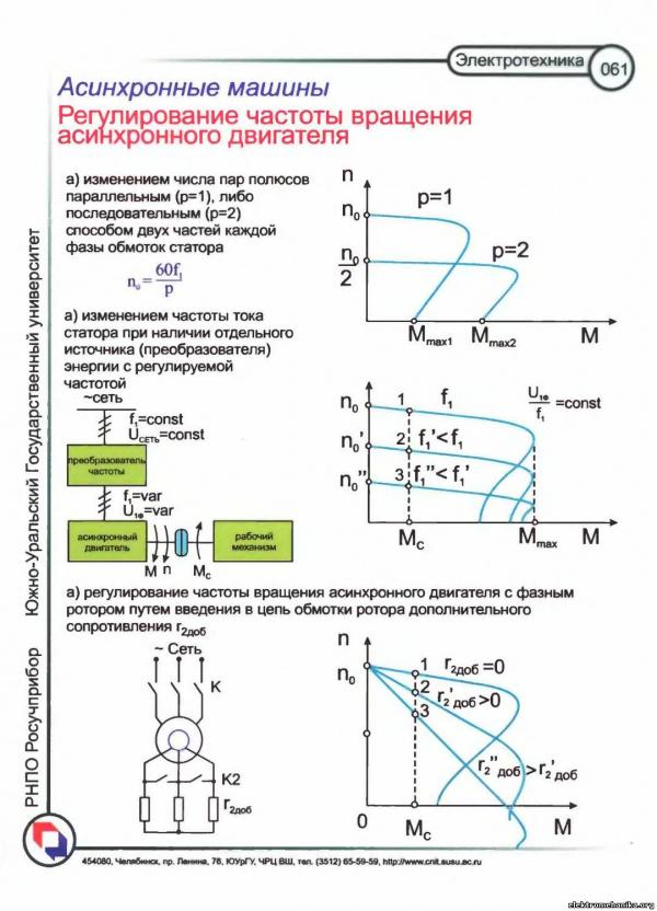
To control the speed of asynchronous motors with a squirrel-cage rotor, the frequency control method is usually used, which is a smooth speed control magnetic field by adjusting the frequency of the current in the stator windings, and the method of changing the number of pole pairs of a rotating magnetic field, in which the frequency of rotation of the magnetic field changes abruptly.
Will the problem be with the electric motor running very low at 300rpm? Even the altitude at which you operate the engine matters, as the air at higher altitudes is less dense and therefore does not provide the same cooling effect. In mountainous areas it may be necessary to reduce the load even at full speed to ensure sufficient engine cooling. The specifics of your application will most likely require the use of a high efficiency motor and constant speed fan. The cost of an auxiliary fan will depend on the motor frame size and may even require some fabrication to figure out how to mount it. Thanks for any advice you can give me!
To control the speed of rotation of asynchronous motors with a phase rotor, the method of rheostatic control is used, which is a smooth control of the slip of the rotor by changing the active resistance of its phase windings.
Frequency regulation. The most promising method of speed control induction motor is stator AC frequency regulation engine. Angular velocity of the rotating field n = 2 f/r. Therefore, when the current frequency f changes, the angular velocity of the field changes proportionally. However, when carrying out frequency control of the current, it must be taken into account that simultaneous voltage control is necessary. This is due to the fact that, in accordance with expression (14.10), the EMF of the phase, and hence the supply voltage, are proportional to the current frequency and flow. Since the flux must remain the same in all modes, the voltage must be (without taking into account the voltage drops in the machine) proportional to the frequency. In addition, this is necessary so that when the engine speed changes, its torque does not change.
multipoint single phase motor is not actually a multi-speed motor, it is a multi-voltage motor. When using winding taps to increase the resistance of the circuit, the motor is weakened and the load causes the motor to slow down. Remove the load and the motor will run at the same speed regardless of the selected crane. If the motor is used as a fan motor, a rheostat can be added to the input line by adding an external resistance and dampening the motor to get the desired speed. If you prefer specific speeds rather than a range of speeds, you can add sample and air resistance measures. Just keep in mind that if your workload changes, so will your speed. Can we change the pole of 3 phase induction motor?
To evaluate the nature of the dependence of the torque on the frequency of the current in the stator windings and on the voltage on it, we neglect in equation (14.28) the active resistance of the stator winding g l and inductive reactances scattering of the stator windings x pac 1 and rotor x ras 2 and use the expression for the slip frequency (14.13):
Mvr= = A,
Please tell me the consequences. Yes, you can re-wind the winding to change the magnetic poles, but in doing so you will need to change a few other characteristics of the winding. To increase the number of poles, you need to change the range, wire size, and turns per coil to keep the back iron and tooth magnetic flux density at normal standards. By maintaining the same number of revolutions, you weaken the engine, reducing its ability to produce torque. Induction motor with squirrel-cage rotor creates a great generator when it moves above its synchronous speed.
where BUT= const.
Therefore, when changing the frequency of the current, in order to maintain the torque constant, it is necessary to proportionally change the voltage on the stator; in other words, the condition for maintaining a constant motor torque during frequency control will be U 1 /f= const. If you adjust the frequency of current and voltage, observing the specified condition, then the mechanical characteristics of the motor will remain rigid, and maximum moment almost independent of frequency (it decreases significantly only at a relatively low frequencies). At the same time, the power will change in proportion to the frequency of the current, since P 2 = M vr. For example, when the current frequency is reduced by a factor of 2, the motor power on the shaft is also halved.
The same features that make this motor desirable over other types of motors make the induction generator desirable over other types of generators, namely the inherent strength of the squirrel frame design and the simplicity of the control systems.
An induction motor becomes a generator when it is connected to the mains and then driven above its synchronous speed by some prime mover. The first engine could be a turbine, an engine, a windmill, or anything capable of providing the torque and speed needed to drive the engine into an overspeed state.
Regulation by changing the number of pairs of poles. A stepwise change in the angular velocity of an induction motor over a wide range is feasible at the cost of complicating and increasing the cost of the design of an induction motor - this is regulation by switching the number of pole pairs of the motor.
At a constant network frequency, the angular velocity of a rotating field depends only on the number of pole pairs of this field, determined by the stator winding. If two separate windings are placed on the stator - one forming R steam, and the other, forming R" pairs of poles, then, by including the first or second winding in the network, we will obtain the field rotation frequency:
Performance as a generator will be slightly different from that used as an engine. The differences may be so small that they cannot be detected by conventional field measurement methods. The main advantage of the induction generator is frequency regulation. Speed must be controlled synchronous generator so that its frequency does not deviate from the linear frequency. The output frequency and volts are controlled by the power system in induction generators and are independent of speed changes.
N 1 \u003d 60f / p or n" 1 = 60f/p", Consequently,
n1/p" 1 =p"/p,
the engine rotor speeds will also vary accordingly. In this case, the winding of the motor rotor must be made like a squirrel wheel.
The number of poles of the stator windings in this case is mutually unrelated and can be chosen any, depending on the operating conditions of the engine. The regulation itself is reduced to an abrupt change in the frequency of rotation of the motor field. But the rotor speed cannot change abruptly due to the inertia of the entire electric drive system. Only after switching does the corresponding change in the rotor speed begin.
The self-regulating effect minimizes the complexity of the control system. Induction generator regulators are very similar to those used for an induction motor, with a few exceptions. In the event of a loss of electrical load, the prime mover's torque will rapidly accelerate the system to potentially dangerous speeds. A brake, governor or throttle is required to prevent dangerous speeds. Electric switch must be equipped to limit the current short circuit. In the event of a short circuit fault in the power system, the generator supplies a fault current. Usually current limiting fuses. The torque of the prime mover must be limited to prevent the generator from being overloaded. This control may be related to the design of the prime mover or may be based on feedback signals from the generator output. In an extreme case, the prime mover can push the generator's torque, causing a runaway speed. In some cases, the speed of the prime mover may drop below the synchronous speed of the generator. If this happens, the generator will be driven to operate the system. If such a response is undesirable, then the power can be cut off with a power reversing relay, or an overload clutch can be used to allow the motor to run without load. The system must be equipped with a speed limiter. . An induction generator may be used as a motor to accelerate the system to operating speed, or a prime mover may be used to provide acceleration.
To show this transient process more clearly, we construct two mechanical characteristics asynchronous machine with a variable number of pole pairs: one characteristic corresponding to R pairs of poles, and the second p" = 1p pairs of poles (respectively, Fig. 14.31, a and b). Let us assume that the moment on the motor shaft remains constant when the field speed changes. With an increase in the latter, i.e., with the transition from R" to R pairs of poles, the motor first finds itself in conditions close to starting, and a current surge occurs.
In the latter case, there is no need to take into account the moment of starting and the current in the design of the machine. This allows the designer to get maximum performance at full load. The induction generator is increasingly being used as a means of recovering energy that would otherwise be wasted. The generated power can be consumed on site or sold to the utility system supplying the site. To convert this energy into electrical energy wind and water generators are used.
Some typical applications of induction generators. In the event of a steam failure, the generator can be used as a motor to drive the pump. In addition, the pump will prevent the system from over-speeding in the event of a loss of electrical load. The water company believes that it can buy electricity at low prices during the night and sell electricity at a high rate during the daytime peak period. He builds low and high storage tanks and installs several pumps. At night, he pumps water from the low pool to the high pool, buying electricity from the utility. During peak periods, water flows back through the pumps, driving the engines as generators. Power is sold to utilities. This circuit is so simple that it can be remotely controlled. The wind blows constantly between the desert and mountains of California. An enterprising man created several towers with windmills that control induction generators through gearboxes. Power is generated in proportion to wind speed and sold to a local utility. The indiscriminate use of induction motors as generators should be avoided. It is possible that a particular motor will not perform well as a generator due to internal magnetic saturation. Internal stress as a generator may be higher than as a motor with the same terminal voltage. The magnetic densities in a machine are determined by the voltage in the equivalent air gap. It's over high voltage in the air gap can lead to excessive saturation of the machine, as well as high core losses and increased magnetizing currents. It can be assumed that the machine may overheat at very low load. If an induction motor is used as a generator, this information must be known to the designer so he can make appropriate allowances in magnetic densities. Induction motors are typically rated at 460 volts for use on a 480 volt system. Induction generators must be rated for system voltage rating or slightly higher, not lower, as the generator is now the power source and not the load on the power system. Power factor correction capacitors can be used to correct the power factor of a generator in the same way as for an induction motor. However, if there is a possibility that the generator may overspeed, whether it is connected to the power system or not, the capacitors must be connected to the system through a separate breaker so that when the generator breaker is opened, the capacitors will not be connected to the generator. Under overspeed conditions, capacitors can overload the generator and cause uncontrolled high voltage. These voltages can destroy generator insulation systems and can also be hazardous to other equipment and personnel. The paper mill has a significant stock of available fuel in bark and scrap. . Induction generators are designed for specific applications and not for general use.
But when moving from R to R", i.e., with a decrease in the frequency of rotation of the field, the machine first finds itself in the conditions of a generator mode and works, giving energy to the network.
This mode is sometimes used for quick and economical braking of the drive.
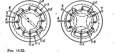
Two separate windings are supplied to the stators only for low power motors; for high power motors, it is more expedient to switch coils of the same winding to obtain a different number of pole pairs. On fig. 14.32 shows the switching circuit three-phase winding from two to four poles. Switching the winding in a ratio other than 1:2 requires a more complex circuit change and is less common.
Please contact your local distributor or sales representative to submit a technical request. Only those who know the differences can already choose the right control method when designing a drive - and thus keep costs as low as possible.
When designing an electrical drive system, it is critical to determine the precision requirements for application control. If the requirements are transparent and specified, the drive system can be compiled and adjusted with the required components. The main goal is to select the right components with specific control quality requirements in a cost-optimized way - this is the only way to avoid unnecessary overheads if, for example, the requirements were rated too high or too low.
In most cases, the stator of an asynchronous machine is supplied with two independent windings, each of which is switched in a ratio of 1: 2 or otherwise. Thus, the engine has four speed stages, for example 3000, > 1500, 1000 and 500 rpm.
Rheostatic regulation. In three-phase asynchronous motors with a phase rotor, a rheostatic method of controlling the rotor speed is used. This is achieved by introducing an adjustable three-phase rheostat into the circuit of the phase windings of the rotor, as when starting the engine (Fig. 14.24). But this rheostat must be designed for a long-term load by the rotor current, and not for a short-term load, like a starting rheostat. An increase in the active resistance of the rotor circuit changes the characteristic M(s) - makes it softer (see fig. 14.25). If, at a constant torque on the motor shaft, the active resistance of the rotor circuit is increased by gradually increasing the resistance of the rheostat (r p1< rp2< r р3), то рабочая точка будет смещаться с одной кривой M(s) to the next, corresponding to the increased resistance of the rotor circuit (Fig. 14.25, points 1-4), according to which the slip will increase, and consequently, the engine speed will decrease.
In this way, it is possible to change the rotor speed in the range from nominal to full stop. But with this method of regulation, relatively large energy losses are inevitable (see § 14.11). Rotating field power R vr, p without taking into account the energy losses in the stator core, it consists (see Fig. 14.20) of the power losses in the conductors of the rotor winding (see the equivalent circuit in Fig. 14.19);
R pr2 \u003d r "in2 (I" 2) 2
and mechanical power
P fur \u003d r "in 2 (I" 2) 2.
Attitude
R pr 2 / R mech \u003d s / (l -s) \u003d (n 1 - n)/n
shows that dividing the mechanical power decreases in direct proportion to the decrease in the rotor speed, at the same time, the proportion of power losses in the active resistance of the rotor circuit increases accordingly. Therefore, to reduce the engine speed, for example, by 25%, it is necessary to include a rheostat in the rotor circuit with such active resistance, in which a quarter of the energy of the rotating magnetic field will be uselessly converted into heat. The disadvantage of such regulation may also be the fact that the inclusion of a rheostat in the rotor circuit makes mechanical characteristic the engine is softer, therefore, reduces the stability of its speed. When the rheostat is on, small changes in the load on the shaft cause significant changes in the engine speed.
There are positions in electrical installations when you cannot do without a DC motor. It is this electric motor that can be adjusted according to the speed of rotation of the rotor, which is required in electrical installations. True, it has a lot of shortcomings, and one of them is the rapid wear of the brushes if they were installed with a curvature, and their service life is quite low. When worn, sparking occurs, so such an engine cannot be used in explosive and dusty rooms. Plus an electric motor direct current it costs expensive. To change this situation, use an asynchronous motor and a frequency controller for an asynchronous motor.
In almost all respects, electric motors operating on alternating current are superior to analogues on direct current. First, they are more reliable. Secondly, they have smaller dimensions and weight. Thirdly, the price is lower. Fourth, they are easier to operate and connect.
But they have one drawback - this is the complexity of regulating the speed. In this case, the standard methods of controlling the frequency of asynchronous motors will not work here, namely, changing the voltage, setting the resistance, and so on. Frequency control of an asynchronous electric motor was the number one problem. Although the theoretical basis has been known since the thirties of the last century. It all boiled down to cost. frequency converter. Everything changed when microcircuits were invented, with the help of which, through transistors, it became possible to assemble a frequency converter with a minimum cost.
Regulatory principle
So, the way to control the speed of an induction motor is based on one formula. Here she is below.
ω=2πf/p, where
- ω is the angular speed of rotation of the stator;
- f is the input voltage frequency;
- p is the number of pole pairs.
That is, it turns out that it is possible to change the speed of rotation of the electric motor only by changing the voltage frequency. What does it give in practice? The first is the smooth operation of the motor, especially when starting the equipment, when the engine itself is operating under the highest loads. The second is increased slip. Due to this, the efficiency increases, and the loss of power characteristics decreases.
The structure of the frequency controller
All modern frequency converters are built on the principle of the so-called double conversion. That is, alternating current is converted to DC through an uncontrolled rectifier and filter. Further, through a pulse inverter (it is three-phase), the reverse conversion of direct current into alternating current takes place. The inverter itself consists of six power switches (transistor). So, each winding of the electric engine is connected to certain rectifier keys (positive or negative). It is the inverter that changes the frequency of the voltage that is applied to the stator windings. In fact, it is through it that the frequency regulation of the electric motor occurs.
In this device, power transistors are installed at the output. They act as keys. If we compare them with thyristors, it should be noted that the former generate a signal in the form of a sinusoid. It is this form that creates minimal distortion.
Now the very principle of operation of the frequency converter. To understand this, we propose to disassemble the figure below.
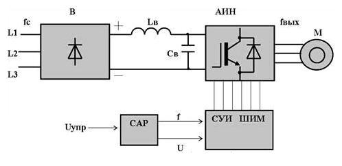
So, let's go through the picture, where
- "B" is an uncontrolled diode-type power rectifier.
- "AIN" is an autonomous inverter.
- "SUI PWM" - a system of pulse-width control.
- "SAR" - automatic control system.
- "Sv" - filter capacitor.
- "Lv" - throttle.
The diagram shows very clearly that the inverter regulates the voltage frequency due to the pulse-width control system (it is high-frequency). It is this part of the regulator that is responsible for connecting the stator windings of the electric motor alternately to the positive pole of the rectifier, then to the negative. The frequency of connection to the poles occurs along a sinusoidal curve. In this case, the pulse frequency is determined precisely by the PWM frequency. This is how frequency regulation works.
We advise you to read
, diagnosis, treatment Treatment of urogenital chlamydia") Urogenital chlamydia - description, causes, symptoms (signs), diagnosis, treatment Treatment of urogenital chlamydia
Urogenital chlamydia - description, causes, symptoms (signs), diagnosis, treatment Treatment of urogenital chlamydia The benefits and significance of hydroamino acid threonine for the human body L threonine what
 To wait or not to wait for a guy from the army For what reason can they be commissioned from the army
 Baked apples with cottage cheese Baked apples with cottage cheese

