General information.
Any asynchronous three-phase motor is designed for two rated voltages of a three-phase network 380 / 220 - 220/127, etc. The most common motors are 380 / 220V. The motor is switched from one voltage to another by connecting the windings to a star - for 380 V or to a delta - for 220 V. If the motor has a connection block that has 6 pins with jumpers installed, you should pay attention to the order in which the jumpers are installed . If the engine does not have a block and there are 6 leads, they are usually assembled in bundles of 3 leads. In one bundle, the beginnings of the windings are assembled, in the other, the ends (the beginnings of the windings in the diagram are indicated by a dot).
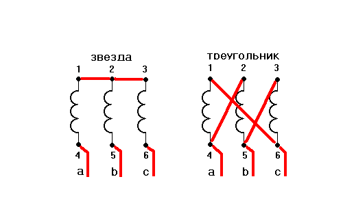
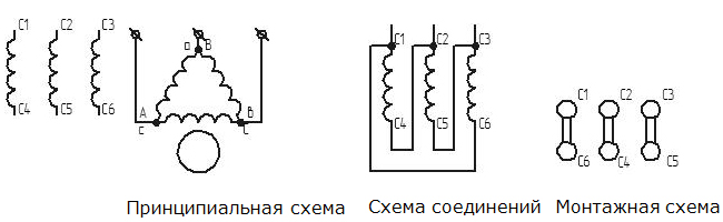
In this case, “beginning” and “end” are conditional concepts, it is only important that the directions of the windings coincide, that is, in the example of a “star”, both the beginnings and ends of the windings can be the zero point, and in the “triangle” - the windings should be connected in series, i.e. the end of one with the beginning of the next. For correct connection on the "triangle" you need to determine the conclusions of each winding, decompose them in pairs and connect in the next. scheme:
If you expand this diagram, you will see that the coils are connected in a "triangle".
If the engine has only 3 outputs, you should disassemble the engine: remove the cover from the block side and find the connection of three in the windings winding wires(all other wires are connected by 2). The connection of the three wires is the zero point of the star. These 3 wires should be broken, soldered to them with lead wires and combined into one bundle. Thus, we already have 6 wires that need to be connected in a triangle pattern.
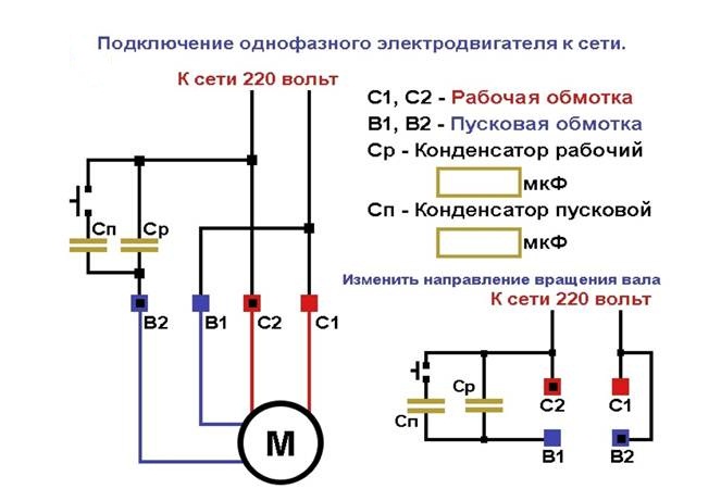
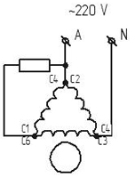
A three-phase motor can quite successfully work in single-phase network, but one should not expect miracles from him when working with capacitors. Power in the best case will be no more than 70% of the nominal value, the starting torque is highly dependent on the starting capacity, the difficulty of selection working capacity under changing load. A three-phase motor in a single-phase network is a compromise, but in many cases this is the only way out. There are formulas for calculating the capacitance of the working capacitor, but I consider them incorrect for the following reasons: current in the winding. 2. Rated capacity capacitor indicated on its case differs from the actual + / - 20%, which is also indicated not on the capacitor. And if you measure the capacitance of a single capacitor, it can be twice as large or half as small. Therefore, I propose to select the capacitance for a specific motor and for a specific load, measuring the current at each point of the triangle, trying to equalize as much as possible by selecting the capacitance. Since the single-phase network has a voltage of 220 V, the motor should be connected according to the "triangle" scheme. To start an unloaded engine, you can do with only a working capacitor.
The direction of rotation of the motor depends on the connection of the capacitor (point a) to point b or c.
Practically, the approximate capacitance of the capacitor can be determined from the next. formula: C uF \u003d P W / 10,
where C is the capacitance of the capacitor in microfarads, P is the rated power of the motor in watts. To begin with, it is enough, and fine adjustment should be made after loading the engine with a specific job. The operating voltage of the capacitor should be higher than the mains voltage, but practice shows that old Soviet paper capacitors rated for 160V work successfully. And they are much easier to find, even in the trash. My drill motor works with such capacitors, located to protect against cotton in a grounded box from the starter, I don’t remember how many years and so far everything is intact. But I do not call for such an approach, just information for thought. In addition, if you turn on 160 and Volt capacitors in series, we will lose twice in capacity, but the operating voltage will double 320V, and a battery of the required capacity can be assembled from pairs of such capacitors.
The inclusion of engines with revolutions above 1500 rpm, or loaded at the time of starting, is difficult. In such cases, a starting capacitor should be used, the capacity of which depends on the engine load, is selected experimentally and can be approximately equal to the working capacitor to 1.5 - 2 times greater. In the future, for clarity, everything related to work will be green, everything related to starting will be red, everything related to braking will be blue.
In the simplest case, you can turn on the starting capacitor using a non-fixed button.
To automate the start of the engine, you can use a current relay. For motors up to 500 W, a current relay from washing machine or a refrigerator with a slight alteration. Since the capacitor remains charged even when the engine is restarted, a rather strong arc occurs between the contacts and the silver contacts are welded without disconnecting the starting capacitor after the engine is started. To prevent this from happening, the contact plate of the starting relay should be made from a graphite or carbon brush (but not from copper-graphite, since it also sticks). It is also necessary to disable the thermal protection of this relay if the motor power exceeds the rated power of the relay.
If the engine power is higher than 500 W, up to 1.1 kW, you can rewind the starting relay winding with a thicker wire and with fewer turns so that the relay turns off immediately when the engine reaches rated speed.
For a more powerful engine, you can make homemade relay current, increasing the size of the original.
Most three-phase motors up to three kW work well in a single-phase network, with the exception of motors with a double squirrel cage, of ours this is the MA series, it is better not to mess with them, they do not work in a single-phase network.
Practical switching schemes.
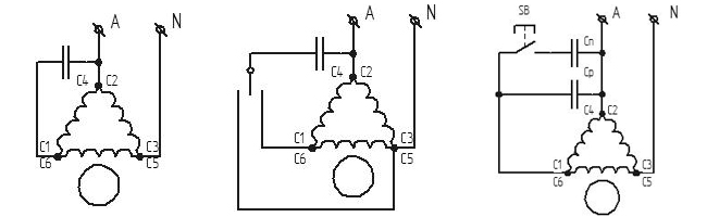
Generalizing switching circuit
C1 - starting, C2 - working, K1 - non-latching button, diode and resistor - braking system.
The circuit works as follows: when the switch is moved to position 3 and the K1 button is pressed, the engine starts, after the button is released, only the working capacitor remains and the engine runs on the payload. When the switch is set to position 1, a direct current is applied to the motor winding and the motor is braked, after stopping, it is necessary to turn the switch to position 2, otherwise the motor will burn out, so the switch must be special and fixed only in positions 3 and 2, and position 1 must be turned on only on hold. With a motor power of up to 300W and the need for rapid braking, a quenching resistor can be omitted, with a higher power, the resistor resistance is selected according to the desired braking time, but should not be less than the resistance of the motor winding.
This circuit is similar to the first one, but braking here occurs due to the energy stored in the electrolytic capacitor C1 and the braking time will depend on its capacitance. As in any circuit, the start button can be replaced with a current relay. When the switch is turned on, the engine starts and the capacitor C1 is charged through VD1 and R1. The resistance R1 is selected depending on the power of the diode, the capacitance of the capacitor and the time the engine is running before braking. If the engine operation time between starting and braking exceeds 1 minute, you can use the KD226G diode and a 7kΩ resistor of at least 4W. operating voltage of the capacitor is at least 350V. For fast braking, a capacitor from a flash is well suited, there are many flashes, but there is no need for them anymore. When turned off, the switch switches to the position closing the capacitor to the motor winding and braking occurs direct current. A conventional two-position switch is used.
Scheme of reverse switching and braking.
This scheme is a development of the previous one, here it automatically starts with the help of a current relay and brakes with an electrolytic capacitor, as well as reverse switching. The difference between this circuit: a dual three-position switch and a starting relay. Throwing out unnecessary elements from this scheme, each of which has its own color, you can assemble the scheme you need for specific purposes. If desired, you can switch to push-button switching, for this you will need one or two automatic starters with a 220V coil. A dual three-position switch is used.
Another not quite usual automatic switching scheme.
As in other schemes, there is a braking system here, but it is easy to throw it out if it is not needed. In this switching circuit, two windings are connected in parallel, and the third through the starting system and an auxiliary capacitor, the capacitance of which is approximately two times less than that required when turned on by a triangle. To change the direction of rotation, you need to swap the beginning and end of the auxiliary winding, indicated by red and green dots. The start is due to the charging of the capacitor C3 and the duration of the start depends on the capacitance of the capacitor, and the capacitance must be large enough so that the engine has time to reach the nominal speed. The capacity can be taken with a margin, since after charging the capacitor does not have a noticeable effect on the operation of the engine. Resistor R2 is needed to discharge the capacitor and thereby prepare it for the next start, 30 kOhm 2W will do. Diodes D245 - 248 will suit any engine. For motors of lower power, both the power of the diodes and the capacitance of the capacitor will decrease accordingly. Although it is difficult to make reverse switching according to this scheme, it is possible if desired. You will need a complex switch or starting machines.
The use of electrolytic capacitors as starting and working.
The cost of non-polar capacitors is quite high, and not everywhere they can be found. Therefore, if they are not there, you can use electrolytic capacitors, included in the circuit is not much more complicated. Their capacity is large enough with a small volume, they are not scarce and not expensive. But new factors must be taken into account. The operating voltage must be at least 350 volts, they can only be switched on in pairs, as indicated in the diagram in black, and in this case the capacitance is halved. And if the engine needs 100 microfarads to run, then capacitors C1 and C2 should be 200 microfarads each.
Electrolytic capacitors have a large capacitance tolerance, so it is better to assemble a capacitor bank (marked in green), it will be easier to select the actual capacity needed by the engine, and in addition, electrolytes have very thin leads, and the current at large capacity can reach significant values and the conclusions can heat up, and in the event of an internal break, cause an explosion of the capacitor. Therefore, the entire capacitor bank must be kept in a closed box, especially during experiments. Diodes must be with a margin of voltage and current required for operation. Up to 2 kW, D 245 - 248 are quite suitable. When the diode breaks down, the capacitor burns out (explodes). The explosion, of course, is said loudly, the plastic box will completely protect against the scattering of capacitor parts and from the shiny serpentine too. Well, the horror stories are told, now a little construction. As can be seen from the diagram, the minuses of all capacitors are connected together and, therefore, capacitors of the old design with a minus on the case can simply be tightly rewound with electrical tape and placed in a plastic box of the appropriate size. The diodes must be placed on an insulating plate and, at high power, put them on small radiators, and if the power is not high and the diodes do not heat up, then they can be placed in the same box. Electrolytic capacitors included in such a scheme work quite successfully as starting and working ones.
Now in refinement electronic circuit inclusion, but so far it is difficult to repeat and configure.
Some craftsmen independently assemble wood or metal processing machines at home. For this, any available motors of suitable power can be used. In some cases, you have to figure out how to connect a three-phase motor to a single-phase network. This article is devoted to this topic. It will also talk about how to choose the right capacitors.
Single-phase and three-phase
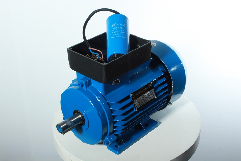
In order to correctly understand the subject of discussion, which explains the connection of a 380 to 220 volt engine, it is necessary to understand what is the fundamental difference between such units. All three-phase motors are asynchronous. This means that the phases in it are connected with some offset. Structurally, the engine consists of a housing in which a static part is placed that does not rotate, it is called the stator. There is also a rotating element called the rotor. The rotor is inside the stator. Three-phase voltage is applied to the stator, each phase is 220 volts. After that, an electromagnetic field is formed. Due to the fact that the phases are in angular displacement, there appears electromotive force. It causes the rotor, which is in the magnetic field of the stator, to rotate.
Note! Winding voltage three-phase motor is supplied through the type of connection that is made in the form of a star or a triangle.
Single-phase asynchronous units have a slightly different type of connection, because they are powered by a 220 volt network. It has only two wires. One is called phase, and the second is zero. To start, the motor needs only one winding to which the phase is connected. But only one will not be enough for a starting impulse. Therefore, there is also a winding that is involved during start-up. In order for it to fulfill its role, it can be connected through a capacitor, which happens most often, or briefly closed.
Connecting a three-phase motor
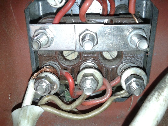
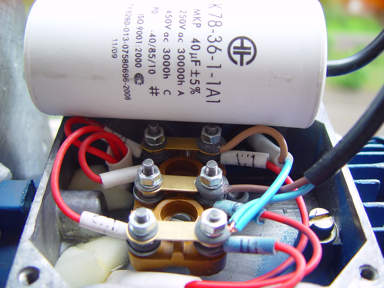
The usual connection of a three-phase motor to a three-phase network can be a daunting task for those who have never encountered it. Some units have only three wires to connect. They allow you to do this according to the "star" scheme. Other devices have six wires. In this case, there is a choice between a triangle and a star. Below in the photo you can see a real example of a star connection. In the white winding, the power cable is suitable, and it is connected to only three terminals. Further, special jumpers are installed, which provide proper nutrition windings.
To make it clearer how to implement it yourself, below will be a diagram of such a connection. The delta connection is somewhat simpler, since three additional terminals are missing. But this only means that the jumper mechanism is already implemented in the engine itself. At the same time, it is not possible to influence the method of connecting the windings, which means that it will be necessary to observe the nuances when connecting such an engine to a single-phase network.
Connection to a single-phase network
A three-phase unit can be successfully connected to a single-phase network. But it should be borne in mind that with a scheme called a "star", the power of the unit will not exceed half of its rated power. To increase this figure, it is necessary to provide a triangle connection. In this case, it will be possible to achieve only a 30% drop in power. At the same time, you should not be afraid, because in a 220-volt network it is impossible for a critical voltage to occur that would damage the motor windings.
Wiring diagrams
When a three-phase motor is connected to a 380 network, then each of its windings is powered from one phase. When connecting it to a 220 volt network, a phase and neutral wire comes to two windings, and the third remains unused. To correct this nuance, it is necessary to choose the right capacitor, which at the required moment can apply voltage to it. Ideally, there should be two capacitors in the circuit. One of them is a launcher, and the second is a worker. If the power of a three-phase unit does not exceed 1.5 kW, and the load is applied to it after it has gained the required speed, then only a working capacitor can be used.
Note! Without additional capacitors or other devices, it will not work to connect the motor directly to 380 to 220.
In this case, it must be installed in the gap between the third contact of the triangle and the neutral wire. If it is necessary to achieve an effect in which the motor will rotate in the opposite direction, then it is necessary to connect not a zero, but a phase wire to one terminal of the capacitor. If the engine exceeds the power indicated above, then a starting capacitor will also be needed. It is mounted parallel to the worker. But it should be borne in mind that a non-latching switch must be installed on the gap in the wire that is between them. This button will allow you to use the capacitor only during start-up. In this case, after turning on the engine in the network, hold this key for several seconds in order for the unit to gain the required speed. After that, it must be released so as not to burn the windings.
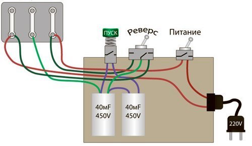
If it is necessary to implement the inclusion of such a unit in reverse, then a three-pin toggle switch is mounted. The middle one must be constantly connected to the working capacitor. The outer ones must be connected to the phase and neutral wires. Depending on which direction the rotation should be, you will need to set the toggle switch to either zero or phase. Below is a schematic diagram of such a connection.
Capacitor selection
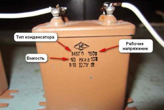
There are no universal capacitors that would fit all units indiscriminately. Their characteristic is the capacity that they are able to hold. Therefore, each will have to be selected individually. The main requirement for it will be to work at a mains voltage of 220 volts, more often they are designed for 300 volts. To determine which element is required, you must use the formula. If the connection is made by a star, then it is necessary to divide the current strength by a voltage of 220 volts and multiply by 2800. The figure indicated in the engine characteristics is taken as the current strength indicator. For a triangle connection, the formula remains the same, but the last coefficient is changed to 4800.
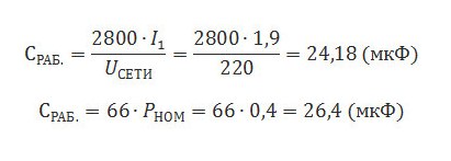
For example, if the unit says that rated current, which can flow through its windings is 6 amperes, then the capacitance of the working capacitor will be 76 microfarads. This is when connected with a star, for connecting with a triangle the result will be 130 microfarads. But it was said above that if the unit experiences a load at start-up or has a power of more than 1.5 kW, then one more capacitor is needed - a starting one. Its capacity is usually 2 or 3 times the working capacity. That is, for a star connection, you will need a second capacitor with a capacity of 150-175 microfarads. It will have to be selected empirically. There may not be capacitors of the required capacity on sale, then you can assemble a block to obtain the required figure. To do this, the available capacitors are connected in parallel so that their capacitance is added.
Note! There is some limitation on the power of three-phase units that can be powered from a single-phase network. It is 3 kW. If this value is exceeded, the wiring may fail.
Why is it better to select starting capacitors empirically, starting with the smallest? The fact is that if its value is insufficient, a larger current will be supplied, which can damage the windings. If its value is greater than required, then the unit will not have enough impulse to start. You can visualize the connection more clearly with the help of video.
Conclusion
While working with electric shock observe safety precautions. Do not start anything if you are completely unsure of the correctness of the connection made. Be sure to consult an experienced electrician who will tell you if the wiring can withstand the required load from the unit.
How to run a three-phase asynchronous motor from a single-phase network?
The easiest way to start a three-phase motor as a single-phase motor is to connect its third winding through a phase shifter. Such a device can be an active resistance, inductance or capacitor.
Before connecting a three-phase motor to a single-phase network, you must make sure that the rated voltage of its windings corresponds to the rated voltage of the network. An asynchronous three-phase motor has three stator windings. Accordingly, 6 terminals for connecting the power supply must be output in the terminal box. If open terminal box then we will see the boron engine. On boron, 3 motor windings are brought out. Their ends are connected to the terminals. The motor power is connected to these terminals.
Each winding has a beginning and an end. The beginning of the windings are marked as C1, C2, C3. The ends of the windings are marked respectively C4, C5, C6. On the cover of the terminal box, we will see a circuit for connecting the engine to the network at different supply voltages. According to this scheme, we must connect the windings. Those. if the motor allows the use of voltages of 380/220, then to connect it to a single-phase 220V network, it is necessary to switch the windings to the “triangle” circuit.
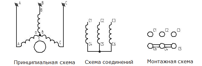
If its connection scheme allows 220/127 V, then it must be connected to a single-phase 220 V network according to the “star” scheme, as shown in the figure.
Circuit with starting active resistance
The figure shows the diagrams of a single-phase connection of a three-phase motor with a starting active resistance. Such a scheme is used only in low-power motors, since a large amount of energy is lost in the form of heat in the resistor.
The most widely used circuits with capacitors. A switch must be used to change the direction of rotation of the motor. Ideal for normal operation such an engine, it is necessary that the capacitance of the capacitor varies depending on the number of revolutions. But such a condition is quite difficult to fulfill, therefore, a two-stage control scheme for an asynchronous electric motor is usually used. To operate the mechanism driven by such an engine, two capacitors are used. One is connected only at start-up, and after the end of the start-up, it is disconnected and only one capacitor is left. In this case, there is a noticeable decrease in its useful power on the shaft to 50 ... 60% of the rated power when turned on in three-phase network. This motor start is called capacitor start.
When using starting capacitors, it is possible to increase the starting torque up to Mp / Mn = 1.6-2. However, this significantly increases the capacity starting capacitor, due to which its dimensions and the cost of the entire phase-shifting device grow. To achieve maximum starting torque, the capacitance value must be chosen from the ratio, Xc=Zk, i.e. the capacitance is equal to the resistance short circuit one stator phase. Due to the high cost and size of the entire phase-shifting device, capacitor starting is used only when a large starting torque is required. At the end of the starting period, the starting winding must be disconnected, otherwise starting winding overheat and burn out. An inductance-choke can be used as a starting device.
Three-phase start induction motor from a single-phase network, through a frequency converter
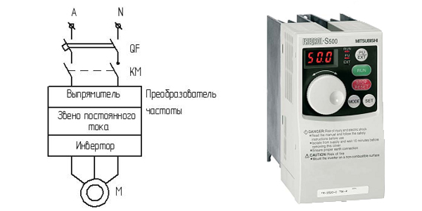
To start and control a three-phase asynchronous motor from a single-phase network, you can use a frequency converter powered by a single-phase network. Structural scheme such a converter is shown in the figure. Starting a three-phase asynchronous motor from a single-phase network using a frequency converter is one of the most promising. Therefore, it is he who is most often used in new developments of control systems for adjustable electric drives. Its principle lies in the fact that, by changing the frequency and voltage of the engine, it is possible, in accordance with the formula, to change its speed.
The converter itself consists of two modules, which are usually enclosed in one housing:
- a control module that controls the operation of the device;
- a power module that feeds the engine with electricity.
The use of a frequency converter to start a three-phase asynchronous motor. allows you to significantly reduce the starting current, since the electric motor has a rigid relationship between current and torque. Moreover, the values of the starting current and torque can be adjusted within fairly large limits. In addition, with the help frequency converter it is possible to regulate the speed of the engine and the mechanism itself, while reducing a significant part of the losses in the mechanism.
The disadvantages of using a frequency converter to start a three-phase asynchronous motor from a single-phase network: the rather high cost of the converter itself and peripheral devices for it. The appearance of non-sinusoidal interference in the network and a decrease in the quality of the network.
We advise you to read
, diagnosis, treatment Treatment of urogenital chlamydia") Chlamydia urogenital - description, causes, symptoms (signs), diagnosis, treatment Treatment of urogenital chlamydia
Chlamydia urogenital - description, causes, symptoms (signs), diagnosis, treatment Treatment of urogenital chlamydia The benefits and significance of hydroamino acid threonine for the human body L threonine what
 To wait or not to wait for a guy from the army For what reason can they be commissioned from the army
 Baked apples with cottage cheese Baked apples with cottage cheese

