The classification of capacitors is based on their division into groups according to the type of dielectric used and according to design features, which determines their use in specific circuits of equipment (Table 14). The type of dielectric determines the main electrical parameters of capacitors: insulation resistance, capacitance stability, losses, etc.
Design features determine the nature of their application: interference suppression, tuning, dosimetric, pulse, etc.
LEGEND SYSTEM
The symbol for capacitors can be abbreviated and complete.
The abbreviated symbol consists of letters and numbers. The first element - a letter or a combination of letters - denotes a subclass of a capacitor:
- To- constant capacity;
- CT- tuning;
- KP- variable capacity.
The second element denotes a group of capacitors depending on the type of dielectric (Table 14). The third element is written with a hyphen and corresponds to the serial number of the development. The composition of the second and third elements in some cases may also include a letter designation.
Conventional designation of capacitors depending on the material of the dielectric
Table 14
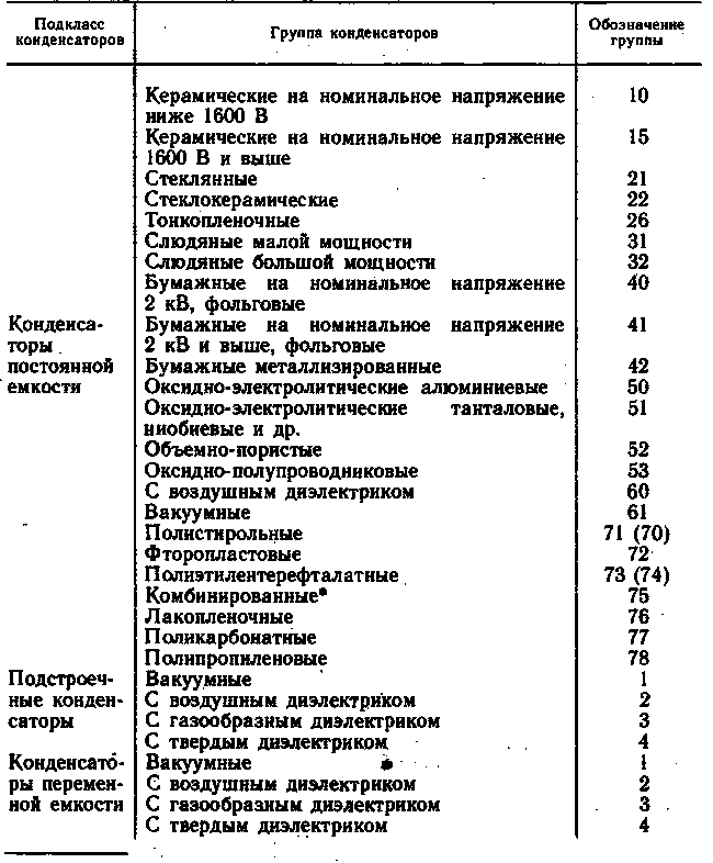
*a combined dielectric consists of a specific combination of layers of different materials.
For old types of capacitors, design, technological, operational and other features were taken as the basis for designations (KD - disc capacitors, FT - fluoroplastic heat-resistant; KTP - tubular through passage capacitors)
The marking on capacitors can be alphanumeric, containing the abbreviation of the capacitor, rated voltage, capacitance, tolerance, TKE group, date of manufacture, or color.
Depending on the size of the capacitors, full or abbreviated (coded) designations of nominal capacities and their permissible deviations are used. Unprotected capacitors are not marked, and their characteristics are indicated on the packaging.
The full designation of nominal capacitances consists of a digital value of the nominal capacitance and a designation of the unit of measurement (pF - picofarads, μF - microfarads, F - farads).
The coded designation of nominal capacities consists of three or four characters, including two or three digits and a letter. A letter from the Russian or Latin alphabet denotes the multiplier that makes up the value of the capacity, and determines the position of the decimal point comma. The letters P (p), H (n), M (m), I (m), F (F) denote the factors 10e -12, 10e -9, 10e -6, 10e -3 and 1. For example, 2.2 pF is denoted 2P2 (2r2), 1500 pF - 1H5 (1n5), 0.1 μF -M1 (m1), 10 μF - 10 M (10m), 1 F - 1F0 (1F0).
Permissible capacity deviations (in percent or in picofarads) are marked after the nominal value with numbers or a code (Table 15).
Permissible deviations of capacity from the nominal value
Table 15
|
Permissible deviation of capacity, % |
The code | The code | Permissible deviation of capacity, % | The code | |
| FROM | |||||
(In parentheses are the old designations)
Color coding is used to mark the nominal capacity, the permissible deviation of the capacity, the rated voltage up to 63 V (Table 16) and the TKE group (see Tables 18, 19). Marking is applied in the form of colored dots or stripes.
PARAMETERS OF CAPACITORS
Nominal capacitance and capacitance tolerance.
Rated capacitance (Cn) - capacitance, the value of which is indicated on the capacitor or indicated in the accompanying documentation. The actual value of the capacitance may differ from the nominal value by the amount of the allowable deviation. Nominal capacitance values are standardized and are selected from certain series of numbers by multiplying or dividing them by 10 n , where n is a positive or negative integer. The most used series of nominal capacities are given in table. 17 (for the values of permissible deviations of capacities, see table. 15).
Color codes for marking capacitors
Table 16
|
Color |
Rated capacity, pF |
|||
|
nominal voltage, V |
||||
|
1 and 2 digit |
factor | tolerances | ||
| Black | 10 | 1 | +/-20% | 4 |
| Brown | 12 | 10 | +/-1% | 6.3 |
| Red | 15 | x10 e2 | +/-2% | 10 |
| Orange | 18 | x10 e3 | +/-0.25pF | 16 |
| Yellow | 22 | x10 e4 | +/-0.5pF | 40 |
| Green | 27 | x10 e5 | +/-5% | 25 or 20 |
| Blue | 33 | x10 e6 | +/-1% | 32 or 30 |
| Violet | 39 | x10 e7 | -20..+50% | 50 |
| Grey | 47 | x10 e-2 | -20..+80% | 3.2 |
| White | 56 | x10 e-1 | +/-10% | 63 |
| Silver | 68 | — | — | 2.5 |
| Gold | 82 | — | — | 1.6 |
The most used series of nominal values of capacities
Table 17![]()
Rated voltage (U H).
This is the voltage marked on the capacitor (or specified in the documentation), at which it can operate under specified conditions during its service life while maintaining parameters within acceptable limits. The rated voltage depends on the design of the capacitor and the properties of the materials used. During operation, the voltage on the capacitor must not exceed the nominal voltage. For many types of capacitors, with increasing temperature (usually more than 70 ... 85 ° C), the allowable voltage (U t) decreases.
Loss tangent (tg b).
It characterizes the active energy losses in the capacitor. The values of the loss tangent of ceramic high-frequency, mica, polystyrene and fluoroplastic capacitors lie within (10 ... 15)x10e -4 , polycarbonate (15 ... 25) x10e -4 , low-frequency ceramic 0.035, oxide capacitors (5 ... 35)%, polyethylene terephthalate 0.01 ... 0.012.
The reciprocal of the loss tangent is called quality factor of the capacitor.
Insulation resistance and leakage current.
These parameters characterize the quality of the dielectric and are used in calculations of high-megohm, time-setting, and low-current circuits. The highest insulation resistance is for fluoroplastic, polystyrene and polypropylene capacitors, slightly lower for low-frequency ceramic, polycarbonate and lavsan capacitors. The lowest insulation resistance of segneto ceramic capacitors.
For oxide capacitors, a leakage current is set, the values \u200b\u200bof which are proportional to capacitance and voltage. Tantalum capacitors have the lowest leakage current (from a few to tens of microamperes), for aluminum capacitors, the leakage current, as a rule, is one or two orders of magnitude higher.
Temperature coefficient of capacity (TKE).
This is a parameter used to characterize capacitors with a linear capacitance versus temperature. Determines the relative change in capacitance with temperature when it changes by one degree Celsius. The TKE values \u200b\u200bof ceramic capacitors and their coded designations are given in table. eighteen.
TKE values of ceramic capacitors and their symbols
Table 18
 * *In cases where two colors are required to designate a TKE group, the second color can be represented by the body color.
Mica and polystyrene capacitors have TKE within (50…200)х10е -6 1/°С, polycarbonate ±50х10е -6 1/°С. For capacitors with other types of dielectric, TKE is not standardized. The permissible change in the capacitance of ferroelectric capacitors with a non-linear dependence of TKE is given in Table. 19.
Changing the capacitance of ceramic capacitors with non-standardized TKE
Table 19
|
Group symbol |
Permissible capacitance change in the temperature range from -60 to +85 °С |
New designation* |
old designation |
|
| coating color |
marking mark |
|||
| H10 | ± 10 |
Orange + black |
Orange | |
| + 20 |
Orange + red |
|||
| H30 | + 30 |
Orange + green |
||
| + 50 |
Orange + blue |
|||
| — 70 |
Orange + purple |
- | ||
| — 90 |
Orange + white |
|||
* In cases where two colors are required to designate a group, the second color may be represented by the body color.
Characteristics of capacitors
Capacitors, like all electronic components, have a number of characteristics, the values of which are not recommended to be exceeded (in order to ensure the reliability and correct operation of the circuit).
Operating voltage:
Since a capacitor is two conductors separated by a dielectric, you must pay attention to its maximum voltage rating. Too much high voltage can cause "breakdown" of the dielectric and the occurrence of an internal short circuit.
Polarity:
Some capacitors are made in such a way that they can only function with the correct voltage polarity. Such limitations are imposed by their design: a microscopically thin layer of dielectric is deposited on one of the plates under the influence of a constant voltage. These capacitors are called electrolytic, and have clear polarity markings.
With reverse voltage polarity, electrolytic capacitors usually fail due to the destruction of the ultrathin dielectric layer. On the other hand, a thin dielectric layer allows high capacitance values to be achieved in a relatively small capacitor package. For the same reason, electrolytic capacitors have a rather low operating voltage (compared to other types of capacitors).
Equivalent Circuit:
Since the plates of a capacitor have some resistance, and since no dielectric is a perfect insulator, there is no such thing as a "perfect capacitor". A real capacitor has an equivalent series resistance and leakage resistance (parallel resistance):
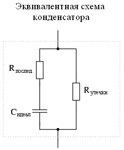
Fortunately, capacitors with low series resistance and high-resistance metering is relatively easy to manufacture.
Physical Size: Size minimization is one of the most important goals of electronic component manufacturers. The smaller the dimensions of the components, the larger the circuit can be implemented in the limited volume of the device case. In the case of capacitors, there are two main factors that limit their minimum size: operating voltage and capacitance. And these factors, as a rule, are opposite to each other. The only way to increase the operating voltage of a capacitor is to increase the thickness of its dielectric. However, in this case, its capacity will decrease. At the same time, the capacitance of the capacitor can be increased by increasing the area of the plates, which will inevitably lead to an increase in size. That's why you can't judge the capacitance of a capacitor by its size. A capacitor of any given size can have a large capacitance and a low operating voltage, or vice versa. Let's take the following two photos as an example:

The physical size of this capacitor is quite large, but it has a small capacitance: only 2 microfarads. But its operating voltage is quite high: 2000 volts! If a given capacitor upgrade by reducing the thickness of the dielectric, then it is possible to achieve a multiple increase in capacitance, but then its operating voltage will drop significantly. Compare this photo with the one below. It shows an electrolytic capacitor, the dimensions of which are comparable to the previous one, but their characteristics (capacity and operating voltage) are directly opposite:

The thin dielectric layer gives this capacitor a much larger capacitance (20,000 microfarads), but significantly reduces the operating voltage.
Below are some samples various types capacitors:

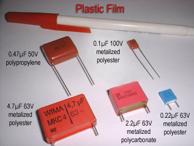


Electrolytic and tantalum capacitors are sensitive to voltage polarity, their cases are marked accordingly.
Capacitors are one of the most common components in electrical diagrams. Pay close attention to the following photo printed circuit board- on it, each component, indicated by the letter "C", is a capacitor:
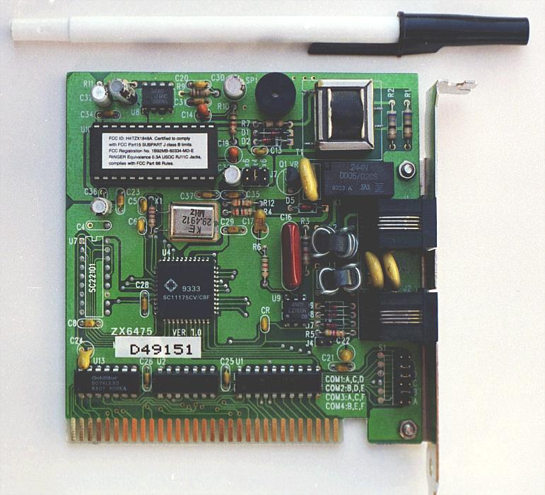
Some of the capacitors shown on the board are ordinary electrolytic ones: for example, C30 (top center) and C36 (left, slightly above center). Some are a special kind of electrolytic capacitors - tantalum: for example C14, C19, C24 and C22 (find them yourself). Tantalum capacitors are relatively large capacity for their physical size.
Examples from even smaller capacitors (for surface mount) can see in this photo:
Here the capacitors are also marked with the letter "C".
"Handbook" - information on various electronic components: transistors, microchips, transformers, capacitors, LEDs etc. The information contains everything necessary for the selection of components and carrying out engineering calculations, parameters, as well as the pinout of cases, typical schemes inclusions and recommendations for the use of radioelements.
Symbols for capacitors
The abbreviated symbol for capacitors consists of the following elements:
first element- a letter or a combination of letters denoting a capacitor (K - a capacitor of constant capacitance; KT - a tuned capacitor; KP - a capacitor of variable capacitance: KS - capacitor assemblies);
second element- a number indicating the type of dielectric used;
third element- the serial number of the development of a particular type.
An example of an abbreviated symbol: K75-10 corresponds to a combined capacitor, design number 10.
The complete symbol consists of the following elements:
first element- abbreviation;
second element- designations and values of the main parameters and characteristics required for ordering and recording in the design documentation (design variant, rated voltage, rated capacitance, permissible deviation of capacitance, group and class for temperature stability);
third element- designation of climatic version, the fourth element - designation of the document for delivery (TU, GOST).
Poimer of the full symbol: K75-10-250 V \u003d 1.0 μF ± 5% \u003d 2 \u003d OZHO. 484.465 TU corresponds to the combined capacitor K75-10 with a rated voltage of 250 V, a rated capacitance of 1.0 μF and a tolerance in capacity of ± 5%, all-climatic version V.
Abbreviated symbols and applications of capacitors are shown in Table 1.
Table 1. Abbreviations, purpose and main applications of capacitors
| Abbreviations | ||
| Fixed Capacitors |
||
| K10 | Ceramic for rated voltages below 1600 V | For high frequency capacitors: thermal compensation, capacitive coupling, fixed loop tuning at high frequency. For low-frequency capacitors: shunt, blocking and filter circuits, coupling between stages at low frequency |
| K15 | Ceramic for rated voltages of 1600 V and above | Capacitive coupling, fixed tuning of high-power high-frequency circuits, pulse devices |
| K21 K22 K23 | glass Glass-ceramic Glass enamel | Blocking, fixed tuning of high-frequency circuits, capacitive coupling, bypass circuits |
| K32 | Mica Low Power Mica high power | Blocking and shunting, high-frequency filter circuits, capacitive coupling, fixed loop tuning |
| K40 | Paper for rated voltage below 1600 V with foil lining | Blocking, buffer, shunt, filter circuits, capacitive coupling |
| Abbreviations | Capacitor type by type of dielectric | Purpose, main areas of application |
| K41 | Paper for a rated voltage of 1600 V and above with foil lining | Blocking, buffer, shunt, filter circuits. capacitive coupling |
| K42 | Paper with metallized linings (metal paper) | Decoupling circuits and filters; are not used as coupling capacities |
| K50 | Electrolytic aluminum | Shunt and filter circuits, energy storage in pulse devices |
| K51 | Electrolytic tantalum foil | They are used in the same circuits as electrolytic aluminum ones, mainly in transistor equipment with increased requirements for capacitor parameters. |
| K52 | Electrolytic tantalum bulk-porous |
|
| K53 | Oxide semiconductor |
|
| K60 K61 | Air gaseous | Capacitance reference standards, high voltage blocking, decoupling, loop capacitors |
| K70 K71 | Polystyrene with foil lining Polystyrene with metallized covers | Accurate timing circuits, integrators, tuned high-Q loops, exemplary |
| K72 | Fluoroplastic | In the same circuits as polystyrene circuits at elevated temperatures and stringent electrical requirements |
| K73 K74 | Polyethylene terephthalate with metallized linings Polyethylene terephthalate with foil linings | In the same circuits as paper capacitors with increased requirements for electrical parameters |
| K75 | Combined | In the same circuits as paper capacitors with increased reliability requirements |
| K76 | Lacquer-film | They can partially replace electrolytic capacitors (especially at elevated values of the variable component). Used in the same circuits as paper, metal-paper and electrolytic capacitors |
| K77 | Polycarbonate | In the same circuits as the K73 capacitors, but with more high frequencies |
| K78 | Polypropylene | In television and household equipment |
| Trimmer capacitors |
||
| CT1 CT2 TGZ CT4 | vacuum FROM air dielectric With gaseous dielectric with solid dielectric | |
| Variable Capacitors |
||
| CP1 CP2 bullpen CP4 | vacuum With air dielectric With gaseous dielectric with solid dielectric | In special equipment In radio receiving equipment In special equipment In radio and television equipment |
The above system does not apply to the symbols of old types of capacitors, which were based on various features: design varieties, technological features, performance characteristics, areas of application, for example: KD - disk capacitors; KM - ceramic monolithic; KLS - ceramic cast sectional; KPK - rigged ceramic capacitors; KSO - compressed mica capacitors; SGM - mica sealed small-sized; KBGI - paper sealed insulated capacitors, MBGCH - metal-paper sealed frequency; KEG - sealed electrolytic capacitors; IT - electrolytic tantalum volume-porous.
Basic parameters of capacitors
Rated capacity - capacitance of the capacitor, indicated on the case or in the accompanying documentation. Nominal capacitance values are standardized.
The International Electrotechnical Commission (IEC) has established seven preferred series for nominal capacitance values: E3; E6; E12; E24; E48; E96; E192.
The numbers after the letter E indicate the number of nominal values in each decimal interval (decade) that correspond to the numbers 1.0; 1.5; 2.2; 3.3; 4.7; 6.8 or numbers obtained by multiplying them and dividing by 10 n , where n is a positive or negative integer.
In the production of capacitors, the series E3, E6, E12, E24 are most often used, less often E48, E96 and E192.
In the symbol, the nominal capacitance is indicated as a specific value, expressed in picoyarads (pF) or microfarads (µF).
The actual value of the capacitance may differ from the nominal value by the value of the permissible deviation in percent. Permissible deviations are coded with the corresponding letters.
Table 2. Permissible deviations of capacity from the nominal value
| The code | Permissible deviation of capacity, % | The code | Permissible deviation of capacity, % | The code |
|
Note. The old notation is in parentheses.
Rated voltage - the voltage indicated on the capacitor (or specified in the documentation), at which it can operate under specified conditions during its service life while maintaining the parameters within acceptable limits. The rated voltage depends on the design of the capacitor and the properties of the materials used. During operation, the voltage on the capacitor must not exceed the rated voltage. For many types of capacitors, with increasing temperature (usually 70 ... 85 ° C), the allowable voltage decreases.
For capacitors with a rated voltage up to 10 kV, the rated voltages are set from the range (GOST 9665-77): 1; 1.6; 2.5; 3.2; four; 6.3; ten; 16; twenty; 25; 32; 40; fifty; 63; 80; 100; 125; 160; 200; 250; 315; 350; 400; 450; 500; 630; 800; 1000; 1600, 2000; 2500; 3000; 4000; 5000; 6300; 8000; 10,000 V.
Temperature coefficient of capacity (TKE). This parameter is used to characterize capacitors with a linear capacitance versus temperature. It determines the relative change in capacitance (in parts per million) from temperature when it changes by 1 ºС. The TKE values of ceramic capacitors and their coded designations are given in table 3.
Table 3. TKE values \u200b\u200bof ceramic capacitors and their symbols
| TKE group designation | Nominal value of TKE, x10 -6 1/ºС | color code |
||
| New designation 1 | old designation |
|||
| Capacitor coating color | Marking point |
|||
| Red+purple | ||||
| Brown | brown |
|||
| blue+red | ||||
| Orange | orange |
|||
1 When two colors are required to designate a TKE group, the second color can be represented by the body color.
Mica and polystyrene capacitors have TKE within (50...200)·10 -6 1/°С, polycarbonate ±50·10 -6 1/°С. For capacitors with other types of dielectric, TKE is not standardized.
For ferro-ceramic capacitors with non-linear and non-standard deviation of capacitance from temperature, the coded designations of permissible deviations are given in Table 4.
Table 4. Change in the capacitance of ceramic capacitors with non-standardized TKE
| Conventional designation of the TKE group | Permissible capacitance change in the temperature range -60...+85 ºС | New designation 1 | old designation |
|
| Capacitor coating color | Marking color |
|||
| Orange+black | Orange | |||
| Orange+red | Orange | |||
| orange+green | Orange | |||
| Orange+blue | Orange | |||
| Orange+purple | Orange | |||
| Orange+white | Orange | |||
1 When two colors are required for the designation of the TKE group, the second color can be represented by the color of the body.
Loss tangent (tg δ) characterizes the energy loss in the capacitor , ceramic low-frequency 0.035, oxide 5 ... 35% polyhalene terephthalate 0 01 ... 0.012.
The reciprocal of the loss tangent is called quality factor of the capacitor
Insulation resistance and leakage current. These parameters characterize the quality of the dielectric and are used in the calculation of high-resistance, time-limited, and low-current circuits. The highest insulation resistance is for fluoroplastic, polystyrene and polypropylene capacitors, slightly lower for high-frequency ceramic, polycarbonate and lysan capacitors. The lowest insulation resistance of ferroelectric capacitors.
For oxide capacitors, the leakage current is normalized, the values \u200b\u200bof which are proportional to capacitance and voltage. Tantalum capacitors have the lowest leakage current (from units to tens of microamperes). For aluminum capacitors, the leakage current is usually one to two orders of magnitude higher.
Coded capacitance designations and color codes of capacitors Depending on the size of the capacitors, full or abbreviated (coded) designations of nominal capacitances and their tolerances are used. Unprotected capacitors are not marked, and their characteristics are indicated on the packaging.
For marking small-sized capacitors, coded (abbreviated) designations are used.
The coded designation consists of numbers indicating the nominal value of the capacitance, and a letter indicating the unit of capacitance and indicating the position of the decimal point.
The full designation of nominal capacitances consists of a digital value of the nominal capacitance and a designation of the unit of measurement (pF - picofarads, μF - microfarads, F - farads).
The coded designation of nominal capacities consists of three or four characters, including two or three digits and the letter. The letters P (p), N (n). M(m), I(1), F(B) denote the factors 10 -12 , 10 -9 , 10 -6 , 10 -3 and 1 respectively for capacitance values expressed in farads. For example, a capacitance of 2.2 pF is designated 2P2 (2p2), 1500 pF - 1H5 (1p5), 0.1 μF - M1 (m1); 10 uF - 10M (10m); 1 farad - 1Ф0 (1F0).
Permissible capacitance deviations (in percent or picofarads) are marked after the nominal value with numbers or a code.
Colored coding is used to mark the nominal capacity, the permissible deviation of the capacity, the rated voltage up to 63 V. The marking is applied in the form of colored dots or stripes in accordance with table 5.
Table 5. Color codes for marking capacitors
| color code | Rated capacity, pF | Capacity tolerance | Rated voltage, V |
|
| First and second digits | Factor |
|||
| Brown | ||||
| Orange | ||||
| 10 4 | ||||
| Violet | 10 7 | |||
| - | ||||
| Silver | ||||
Features of the operation of some types of capacitors. Oxide capacitors with an oxide dielectric can only operate in direct or pulsating current circuits, while the amplitude of the voltage of the variable component must be less than the voltage direct current. It is unacceptable to apply to polar capacitors constant pressure reverse polarity.
When operating oxide capacitors at low voltages, it is necessary to take into account the presence of their own electromotive force(EMF) up to 1 V. In most samples, the polarity of the EMF coincides with the polarity of the capacitors, and in some samples there is a polarity mismatch, as well as a change in polarity over time. Inherent EMF can also occur in type 2 ceramic capacitors when exposed to shock and vibration loads and with a sharp change in temperature.
Counter inclusion of oxide capacitors is allowed - connection by the same poles (plus with plus or minus with minus) of two polar capacitors of the same type with the same nominal capacity and voltage. In this case, the total capacity is reduced by 2 times. Back-to-back capacitors are used as non-polar.
A feature of the operation of oxide-electrolytic capacitors is the presence of leakage current surges at the moment a polarizing voltage is applied to the capacitor. In this case, in the first seconds, the leakage current rapidly decreases and eventually decreases to a steady value. The initial value of the leakage current depends (ceteris paribus) on the time during which the capacitor was inactive (or was in storage). With an increase in storage time and temperature, the leakage current increases, while its recovery time also increases (especially for aluminum capacitors). The most intense increase in the leakage current occurs during prolonged exposure to elevated temperatures without electrical load.
When working with high-voltage capacitors, it is necessary to take into account the phenomenon of absorption of electric charges in the dielectric, which causes incomplete energy return during the rapid discharge of the capacitor to the load. For various types of capacitors, the ratio of the residual voltage on the capacitor to the charging voltage ranges from 3 to 15%, as a result of which the residual voltage can be life-threatening for maintenance personnel.
We advise you to read
, diagnosis, treatment Treatment of urogenital chlamydia") Chlamydia urogenital - description, causes, symptoms (signs), diagnosis, treatment Treatment of urogenital chlamydia
Chlamydia urogenital - description, causes, symptoms (signs), diagnosis, treatment Treatment of urogenital chlamydia The benefits and significance of hydroamino acid threonine for the human body L threonine what
 To wait or not to wait for a guy from the army For what reason can they be commissioned from the army
 Baked apples with cottage cheese Baked apples with cottage cheese

