TECHNOLOGICAL CARD FOR ASSEMBLY AND INSTALLATION OF SUPPORTS IN THE CONSTRUCTION OF OVERHEAD POWER LINES
Application area
A typical technological map is developed on assembly work and installation of supports for power lines.
1. GENERAL INFORMATION ABOUT SUPPORTS
Support types. According to the purpose, the supports are divided into intermediate (P), anchor (A), corner (U), end (K) and special (C). Locations on the route of supports various types were shown on the plan and profile of the 10 kV overhead line section.
Intermediate supports installed on the straight sections of the overhead line route are intended only to support the wires and are not calculated for the load from the tension of the wires along the line. In normal operation, intermediate supports perceive vertical and horizontal loads from the mass of wires, insulators, fittings and wind pressure on the wires and supports. In emergency mode (when one or more wires are broken), the intermediate supports take the load from the tension of the remaining wires, are subjected to torsion and bending. Therefore, they are calculated with a certain margin of safety. Intermediate supports on the lines are 80-90%.
Anchor supports installed on straight sections of the route for crossing overhead lines through engineering structures (roads, communication lines) or natural barriers (ravines, rivers) perceive the longitudinal load from the difference in tension of wires and cables in adjacent anchor spans. During the installation of the line, the anchor supports perceive the longitudinal load from the tension of the wires suspended from one side. Design anchor supports must be rigid and durable.
Corner supports installed at the angles of rotation of the overhead line route, under normal conditions, perceive the resultant of the tensile forces of wires and cables of adjacent spans, directed along the bisector of the angle of rotation of the line. Corner supports are intermediate and anchor. Intermediate ones are installed at small angles of rotation of the line, where the loads are small. At large angles of rotation, anchor supports are used, which have a more rigid structure.
End supports are a type of anchor and are installed at the end or beginning of the line. Under normal operating conditions of the line, they perceive the load from the one-sided pull of the wires.
In addition to the considered so-called normal supports, special supports are also installed on power lines:
transpositional - to change the order of the wires on the supports;
branch lines - for the device of branches from the main line;
cross - for crossing overhead lines in two directions;
anti-wind - to enhance the mechanical strength of overhead lines;
transitional - for crossing overhead lines through natural obstacles and artificial structures, etc.
According to the method of fixing in the ground, the supports are divided into those installed directly into the ground and on the foundations.
According to the design, the supports are divided into free-standing and with braces. Both types of supports can be single-column and portal. Free-standing supports also include A - shaped supports and supports with struts. Free-standing supports are designed to transfer the loads acting on them directly through the posts to the ground or foundation. Racks of supports with braces transfer only vertical loads to the ground or foundation; transverse and longitudinal (relative to the axis of the overhead line) loads are transferred to the ground by braces attached to the anchor plates.
By the number of wires, both supports and overhead lines can be single-, double- and multi-circuit.
According to the material of the support, there are wooden, reinforced concrete and steel.
Arrangement of wires on poles. The number of wires on the supports may be different. As a rule, each overhead line consists of three phases, therefore, the supports of single-circuit overhead lines with a voltage above 1 kV (Fig. 1, a) rely on the suspension of three phase wires (2, 3, 5), that is, one circuit; On the supports of double-circuit overhead lines (Fig. 1, b), two parallel circuits are suspended, that is, six wires (2,3,5 and 6, 7, 8).
Fig.1. The location of the wires on the supports of the overhead line:
a - single-chain,
b - double-chain,
c - up to 1 kV,
d, e - when suspended on single-chain and double-chain according to the "zigzag" scheme;
2, 3, 5, 6. 7, 8 - wires,
4 - lightning protection cable
They also construct overhead lines with split phases, on which, instead of one phase wire of a large cross section, several wires of a smaller cross section fastened together are suspended. Usually, in each phase, 6-220 kV overhead lines are suspended one wire at a time, 330 kV overhead lines - two wires located horizontally, 500 kV overhead lines - three wires at the vertices of a triangle, 750 kV overhead lines - four wires at the corners of a square or five wires at the corners of a pentagon and VL 1150 kV - eight wires at the corners of the octagon. Split phases allow you to increase the transmitted power, reduce losses (with the same wire cross-sectional area), and in some cases refuse to install vibration dampers.
If necessary, one or two lightning protection cables 4 are suspended above the phase wires.
Supports for overhead lines up to 1 kV (Fig. 1, c) allow you to hang from 5 to 12 wires for power supply to various consumers in one overhead line (outdoor and indoor lighting, electric power, household loads). On overhead lines up to 1 kV with a dead-earthed neutral, in addition to the phase ones, a neutral wire is suspended. In addition, wires of lines of different voltages and purposes can be suspended on the same supports.
The arrangement of wires on the supports can be horizontal (in one tier), vertical (one above the other in two or three tiers) and mixed, in which the vertically located wires are horizontally displaced relative to each other. In addition, on single-circuit supports, wires are often arranged in a triangle.
A new system for hanging wires on intermediate supports according to the "zigzag" scheme is being developed and improved. At the same time, on single-circuit overhead lines (Fig. 1, d), the lower wire 5 on the first support is suspended from the lower traverse, and on the second - to the upper one; the lower wire 3 is hung the other way around: on the first support - to the upper traverse, and on the second - to the lower one. The upper wire 2 is fixed on the first support on the right side of the upper traverse, and on the second - on the left. The height of the suspension of the lower wires with this scheme increases on average by half the distance between the lower and upper traverses, which allows you to increase the span between the supports or reduce the height of the supports.
Suspension of wires according to the "zigzag" scheme on double-circuit overhead lines (Fig. 1, e) allows you to further increase the length of the spans, however, the design of the supports is somewhat more complicated.
Unification and designation of supports. Based on the results of many years of practice in the construction, design and operation of overhead lines, the most appropriate and economical types and designs of supports are determined for the corresponding climatic and geographical regions, overhead line voltages and wire brands, and they are systematically unified. At the same time, the number of types of supports and their parts is reduced as much as possible. Many unified parts can be used both for various types of poles, and for poles of overhead lines of different voltages. So, reinforced concrete stepchildren for wooden poles Overhead lines of all voltages are taken of one profile - trapezoidal (three standard sizes).
The unification carried out in 1976 adopted the following system for designating metal and reinforced concrete supports VL 35-330 kV. The letters P and PS denote intermediate supports, PVS - intermediate with internal connections, PU or PUS - intermediate angular, PP - intermediate transitional, U or US - anchor-angle, K or KS - end. The letter B denotes reinforced concrete supports, and its absence indicates that the supports are steel. The numbers 35, 110, 150, 220, etc., following the letters, indicate the voltage of the overhead line, and the numbers following them after the hyphen indicate the size of the supports. The letters U and T are added, respectively, to the designation of intermediate supports used as corner supports and with cable support. For example, the designation PB110-1T is deciphered as follows: an intermediate single-circuit single-column reinforced concrete pole with a cable-resistant one for 110 kV overhead lines.
Wooden poles are designated in accordance with the unification of the years, according to which after the letters P, U, C and D, meaning, respectively, intermediate, anchor-angle, special and wooden poles, there are numbers indicating the voltage of the overhead line and the conditional number of the standard size of the pole (odd - for single-stranded and even - for double-stranded). For example, the designation UD220-1 stands for: wooden anchor-angle single-circuit support for 220 kV overhead lines.
The unification of supports allows the use of industrial methods of their assembly and installation using power tools, cranes, drilling machines, as well as organizing mass production of elements at specialized factories, which reduces the construction time of overhead lines.
Reinforced concrete supports
Reinforced concrete supports are widely used for the construction of overhead lines with voltage up to 750 kV inclusive. At present, the share of overhead lines with reinforced concrete supports is about 80% of the length of all lines under construction.
Reinforced concrete supports have high mechanical strength, are durable and do not require high operating costs. Labor costs for their assembly are much lower than for the assembly of wood and metal. The disadvantage of reinforced concrete supports is their large mass, which increases the cost of transportation and necessitates the use of heavy-duty cranes during assembly and installation.
In reinforced concrete supports, the main forces in tension are taken up by steel reinforcement, and in compression - by concrete. Approximately the same coefficients of thermal expansion of steel and concrete exclude the appearance in reinforced concrete internal stresses with temperature changes. A positive quality of reinforced concrete is also reliable protection of metal reinforcement from corrosion. The disadvantage of reinforced concrete is the formation of cracks in it.
To increase the crack resistance of reinforced concrete structures, prestressing of the reinforcement is used, which creates additional compression of the concrete. As reinforcement, steel wire of a periodic profile or round, rods and seven-wire steel strands are used.
The main elements of reinforced concrete supports are racks, traverses, cable racks and crossbars.
Reinforced concrete racks of an annular section (conical and cylindrical) are made on special centrifugal machines (centrifuges) that form and compact concrete. Racks of rectangular section are made by vibrating, in which the compaction of concrete in molds is carried out by vibrators. For power lines with a voltage of 110 kV and above, only centrifuged racks are used, and for overhead line supports up to. 35 kV - both centrifuged and vibrated.
Centrifuged conical racks SK are manufactured in six standard sizes 19.5-26 m long (butt diameter 560 and 650 mm), and cylindrical STs - seven standard sizes 22.2-26.4 m long (butt diameter 560 mm). The production of new centrifuged cylindrical posts with a length of 20 m and a diameter of 800 mm was launched, on the basis of which free-standing anchor-angle supports were developed for overhead lines up to 330 kV inclusive, as well as intermediate portal supports 40 m high, consisting of two racks connected by flanges.
Vibrated racks of rectangular section have a length of 16.4 m and a cross section of the upper and lower parts, respectively, 200X200 and 380X380 mm. For supports of overhead lines with a voltage of up to 10 kV, vibrated SNV racks 9.5 and 11 m long are used with a cross section of the lower part from 170X 170 to 280X 185 mm, as well as centrifuged conical racks C 10 and 11 m long with a lower base diameter of 320-335 mm and top 170 mm, having through holes for attaching equipment.
VL supports up to 1 kV. On overhead lines up to 1 kV, unified reinforced concrete free-standing single-column (intermediate), as well as single-column with struts and A - shaped (corner, anchor and end) supports are installed. In some cases, anchor and corner supports are assembled from two vertical posts installed side by side.
From the vibrated START racks, single-column supports and supports with struts are assembled, designed to suspend from two to nine wires of overhead lines and two to four wires of a radio network. All types of supports have steel traverses with welded pins. Racks with a height of 9.5 and 11 m are equipped with embedded parts with holes that allow mounting the traverses with one bolt. Outdoor lighting fixtures, cable glands and wire branch brackets can be mounted on these supports.

Fig.2. Reinforced concrete supports of overhead lines up to 1 kV:
a - intermediate,
b - angular,
in - anchor (terminal);
1 - centrifuged conical rack,
2 - brace,
4 - traverses,
5 - undertraverses,
6.7 - anchor and base plates
Figure 2, a - c shows reinforced concrete supports with conical centrifuged racks 10.1 m long and wooden traverses made of impregnated timber with a section of 100X80 mm. Intermediate supports (Fig. 5, a) consist of racks 1 and traverses 4. In weak soils or with a large number of wires, they are reinforced with crossbars.
Angular A - shaped supports (Fig. 2, b) have two racks of the same length, the tops (Fig. 3) of which are interconnected by plates 2 and double traverses 3. The traverses are fixed in settings with through bolts and connected to each other for rigidity by planks 6. On on a tensile stand (see Fig. 2, b), an anchor plate 6 is installed, which increases the pull-out resistance of the support, and on a compressed stand, a base plate 7 is installed, which reduces the specific load on the ground.
Fig.3. Top. A - shaped corner reinforced concrete support of overhead lines up to 1 kV:
1 - centrifuged racks,
2 - plate,
3 - traverses,
5 - traverse mounting bolts,
6 - planks,
The end A - shaped supports (see Fig. 2, c) are similar in design to the angular ones and differ from them in the fastening of the traverses (sub-traverses 5 are used).
Work is underway to create fiberglass traverses, single-column anchor and corner supports. Separate sections of overhead lines with such traverses and supports are in pilot operation.
Supports VL 6-10 kV. On 6-10 kV overhead lines, single-column intermediate, single-column with struts and A - shaped - angular, end and anchor supports are used. Single-column intermediate supports made of vibrated START struts (Fig. 4, a) are equipped with a traverse 2, designed for suspension of three aluminum wires with a cross section of up to 120 mm http://pandia.ru/text/79/172/images/image005_3.gif 238"height="320">
Fig.4. Reinforced concrete single-column supports VLKV:
a - intermediate,
b - angular with a strut;
1 - stand,
2, 3 - steel traverses.
4 - bracket for attaching the strut
Single-column intermediate, as well as corner, end and anchor A - shaped supports from centrifuged racks have standard wooden traverses with a section of 100X80 mm (they are fixed with through bolts and braces), as well as top pins.
Supports VL 35-500 kV. On 35-500 kV overhead lines, unified free-standing and single-column and portal supports with guy wires are used (Fig. 5, a - c), the main elements of which are rack 1, traverses 2 and cable rack 3. Rack 1 has a waterproofing of the lower part at a length of 3.2 m, made with asphalt-bitumen varnish. To prevent moisture from entering the rack, end caps are installed at its ends. The bottom cover, in addition, increases the support area of the rack, which increases the strength of its embedding in the ground. Through holes are made in the upper part of the rack for mounting the traverses. Inside, along the rack in concrete, a special grounding descent is laid.

Fig.5. Intermediate reinforced concrete supports:
a, b - single-column single- and double-circuit for 35-220 kV overhead lines, portal with a metal traverse for 330 kV overhead lines,
2 - traverses,
3 - cable rack,
Traverses are attached to the rack with through bolts (Fig. 6, a) or clamps (Fig. 6, b). Holes are made in the traverses and cable racks for installing special brackets, clamps, rollers, to which coupling fittings are attached - earrings or staples. Rope racks have a welded metal structure and are attached to the rack with clamps.

Fig.6. Fastening traverses to reinforced concrete poles:
a - through bolts;
b - clamps
On 35-220 kV overhead lines, reinforced concrete single-column free-standing single- and double-circuit supports with conical and cylindrical posts are installed as intermediate ones (Fig. 5, a, b), and on 330-500 kV overhead lines - single-circuit portal poles with metal traverses (see fig. .5, c).
As corner anchor supports on 35-110 kV overhead lines, single-column reinforced concrete supports with guy wires are used, and on lines more than high voltage- metal.
In recent years, on 110-330 kV overhead lines, single-column free-standing reinforced concrete poles with racks with a diameter of 800 mm have been used as corner anchor supports.
Metal supports
Metal supports are usually made from steel, and sometimes from aluminum alloys. The high mechanical strength of steel makes it possible to create powerful and high metal supports that can withstand huge mechanical loads. However, such supports are much more expensive than reinforced concrete and wooden ones. In addition, their disadvantage is a small corrosion resistance. Less influenced external environment supports are made of aluminum alloys, but their high cost limits their wide application.
Application area metal supports practically unlimited. Steel poles are installed on power lines of all voltages passing in areas with severe climatic conditions, on hard-to-reach routes and in mountainous areas. Corner and anchor metal supports are installed on 110-500 kV overhead lines, together with intermediate reinforced concrete ones, and also as transitional ones at long crossings.
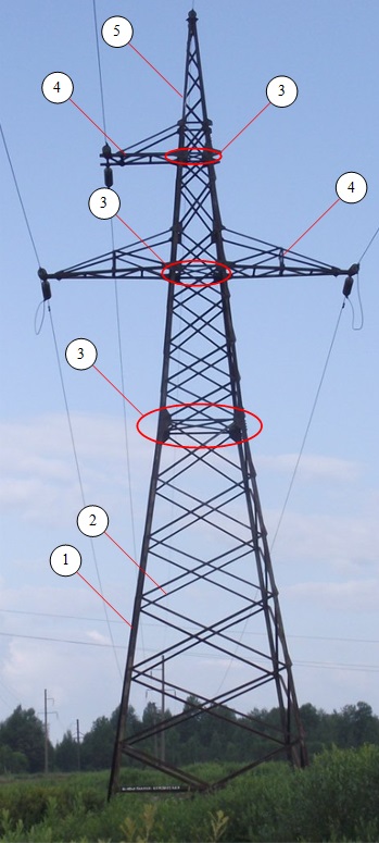
Main elements. By design, steel supports can be single-column (tower) and portal, and by the method of fixing on foundations - free-standing and with braces. At the same time, single-column supports, having the dimensions of the lower part more than the width of the railway car (2.7 m), are called wide-base, and less - narrow-base. The main elements of metal supports (Fig. 7) are trunk 1, traverses 2 and cable rack 3. Some supports have braces 4.
Fig.7. Intermediate metal supports:
a. b - free-standing one - and double-circuit tower type,
c - single-circuit with braces;
2 - traverse,
3 - cable rack,
4 - braces,
5 - anchor plate
The trunk (Fig. 8) is usually a tetrahedral truncated lattice pyramid made of rolled steel profiles (angle, strip, sheet), and consists of a belt 1, a lattice 2 and a diaphragm 3. The lattice, in turn, has bracing rods and spacers, as well as additional connections.
Fig.8. Elements of the metal support barrel:
2 - lattice,
3- aperture
The connections between the chords, diaphragms and bracing rods with the chords can be welded (overlapped) or bolted (Fig. 9, a, b).
![]()
Fig.9. Connection of bracing rods with a support belt;
a - overlap,
b - bolts
Depending on the method of connecting the support elements, they are divided into welded and bolted ones and, accordingly, are made in the form of separate spatial sections or small flat galvanized elements with holes for subsequent assembly on the overhead line route. Sections of welded supports are assembled at the installation site using pads and bolts. Elements of bolted supports, as well as bolts, washers and other parts are shipped from the factories as a set.
When transporting welded supports, the load capacity of machines is used extremely low (no more than 10-30%). Bolted supports are economical in transportation, but require a significant increase in labor costs for assembly (1.5-2 times).
Traverses of single-column supports have a conventional flat frame or spatial structure and are made of channels. For suspension of lightning protection cables, a cable rack in the form of a lattice truncated pyramid is installed on the top of the support shaft. Rope racks of portal supports, as a rule, are mounted on trabepcax. There are holes at the ends of the traverses and cable supports of metal supports or special parts are installed for attaching coupling fittings.
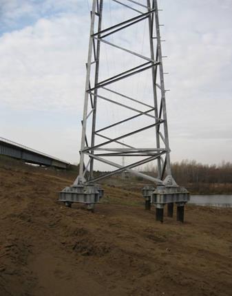
The belts of the trunks of free-standing supports end at the bottom with support shoes - heels, which are attached to the foundations with anchor bolts (Fig. 10, a). Support shafts with braces are attached to the foundations with special hinged heels (Fig. 10, b). The braces of such supports are attached to the traverses (or trunk) on one side, and to the anchor plates on the other (Fig. 10, c). The knots for attaching guy wires to anchor plates allow you to adjust the length and tension of guy wires.

Fig.10. Fastening shoes (heels) of free-standing metal supports (a), with a brace (b) and brace to the anchor plate (c)
Structures of metal supports. The main types of metal poles for 35-500 kV overhead lines are single-column free-standing single-circuit and double-circuit ones with a vertical arrangement of wires, as well as portal braces. For single-circuit lines passing along hard-to-reach routes, single-column supports with guy wires have been developed.
Intermediate supports of 35-110 kV overhead lines (see Fig. 7, a, b) are made in single and double circuit. Free-standing intermediate supports have a welded upper part of a rectangular design with parallel chords. The lower sections are bolted. Wires on a single-circuit support are arranged in a triangle, and on a double-circuit support - in a "barrel". The traverses of double-chain supports are of the same type as those of single-chain ones. On the cable sections of the overhead line, cable racks are mounted at the top of the trunk. The supports are fixed to the foundation with two anchor bolts located on each of the four footrests.
Intermediate supports with braces (see Fig. 7, c) are used only on single-circuit 110 kV overhead lines. These supports have three double split guys. The lower ends of the two guys are attached in pairs to a common anchor, and the upper ends - to the middle of the lower traverses. The third guy, located in the plane of the traverse, is attached directly to the trunk from the side where two traverses are located (upper and lower). Guys are placed at an angle of 120° to one another.
Intermediate supports of 220 and 330 kV overhead lines are similar to 110 kV supports shown in Fig. 7, a, b, and usually have a bolted structure, with the exception of some welded parts (for example, support shoes, traverses), but differ from 110 kV supports in the distance between wires and traverse length. In addition, portal intermediate supports with guys are used on 330 kV lines.
Anchor-angle supports of 35-330 kV overhead lines are made free-standing tower type. Due to heavy loads, the transverse dimensions of the shaft of these supports are significantly increased, and the height of the suspension of the lower wire is reduced.
Painting and galvanizing of supports. To protect against corrosion, metal supports are painted at the manufacturing plants by dipping the finished welded sections into a paint bath. Less commonly, paint is applied with brushes or pneumatic spray guns. Sometimes the supports are painted at the installation site. For priming and painting supports, oil paint, varnishes with aluminum powder and enamels are used.
A more reliable protection of steel supports against corrosion is hot-dip galvanizing. Preliminarily degreased structures are cleaned in a pickling bath with a solution of sulfuric acid, washed with hot running water, covered with flux and lowered into a vertical cylindrical bath with molten lead. In the upper part of the bath, a layer of molten zinc floats on the surface of the lead. When rising from the bath, the structure heated with lead passes through a layer of liquid zinc, which forms a film 0.10-0.12 mm thick on its surface.
The method of protecting the support metal from corrosion in many cases determines the choice of the type of connection of the lattice elements. Thus, the coloring of the supports allows the use of both bolted and welded joints, including overlapping with welding of elements on both sides. At the same time, hot galvanizing does not allow overlap welding of parts, since the acid used to pickle the elements before galvanizing can flow into their gaps and subsequently destroy the connection.
In view of the scarcity of zinc, a pilot-industrial introduction of aluminum coatings has begun, the mechanical strength and adhesion of which are not inferior to those of zinc.
The degree of readiness of metal supports. The number of parts and parts sent from the factory determines the degree (group) of the factory readiness of the support and characterizes the amount of work on its assembly on the overhead line:
Group I - separate elements (in bulk) or separate parts of sections come from the factory; on the VL route, the supports are assembled from bolted elements and parts;
Group II - individual spatial sections and support parts are received from the factory; on the overhead line route, pre-assembly and general assembly on bolts is carried out;
Group III - whole main parts come from the factory that do not require pre-assembly on the track; general assembly is carried out on bolts.
Each element or part of the support sent by the factory has a conditional code called a shipping mark. When completing and assembling the supports on the track, they use the so-called shipping album, which contains drawings of the shipping brands of the supports.
wooden supports
The widespread use of wooden poles is mainly due to the low cost of wood, its sufficiently high mechanical strength, as well as natural round assortment, which provides simplicity of construction and the least resistance to wind loads. The high electrical insulating properties of wood make it possible to use a smaller number of suspension insulators on wooden poles than on metal or reinforced concrete ones, and on overhead lines up to 10 kV, use light and cheap pin insulators. In addition, in some cases, there is no need to hang a lightning protection cable and ground these towers. Reinforced concrete stepchildren or piles are used as foundations for wooden supports.
Wooden supports are about 1.5 times cheaper than reinforced concrete and metal ones, but are less durable. To prolong the service life, the wood of the supports is subjected to anti-rotten treatment (antiseptic treatment) at special factories. It is promising to use supports made of glued wood, the designs of which have been developed recently. Such wood is made from pine boards impregnated with an oil antiseptic and glued together. The use of glued wood makes it possible to increase the service life of supports, eliminate hidden defects, and also use short-length poles.
In the Russian Federation and other countries rich in forest resources (USA, Canada, Sweden, Finland), overhead lines with a voltage of up to 220 kV are built on wooden poles. In the USA, experimental sections of 330 and 460 kV overhead lines were built on wooden supports, and in the Russian Federation similar supports were developed for 330 and 500 kV overhead lines.
Technical properties of wood. For the manufacture of wooden supports, pine, larch and, less often, spruce are used. Pine and larch wood contains a lot of resin and therefore resists moisture well. The poles are made from tree trunks. The lower part of the trunk is called the butt, and the upper, thinner, cut. The natural taper of the trunk from the cut to the butt is called the run.
The strength of wood is largely dependent on moisture content. With a decrease in humidity in wooden supports, due to the shrinkage of the wood, the joints are broken: nuts and bandages are loosened. To obtain wood suitable for the manufacture of supports (with a moisture content of 18-22%), it is dried. The main method is atmospheric, i.e. natural air drying, which, although it is lengthy, gives the best results. In recent years, high-temperature drying of wood in petrolatum, as well as drying with high-frequency currents, has been used.
The strength of wood is also affected by rot, knots, cracks, oblique and other damage. The most dangerous defect is rot, which occurs when wood is damaged by fungi. Decayed wood is covered with small cracks, becomes rotten and disintegrates from a light blow. The most intense decay occurs at a temperature of 20-35 ° C and a humidity of 25-30%.
To protect against decay, the wood is impregnated with oily and mineral antiseptics. Pine is best suited for impregnation; the outer layers of larch and spruce are impregnated with antiseptics very poorly. As oily antiseptics, pure creosote oil or creosote oil mixed with fuel oil, which serves as a solvent, is usually used. The disadvantages of oily antiseptics are their harmful effects on human skin and mucous membranes, as well as flammability. Oily antiseptics are impregnated with finished elements of wooden supports at the factory.
When assembling supports on the track, all places that have been treated are additionally covered with safer mineral antiseptics: sodium fluoride, dinitrophenol, uralite, which are diluted in water. In a number of foreign countries (USA, Canada), a solution of pentachlorophenol in fuel oil or kerosene is widely used for wood impregnation. Other synthetic materials are also being developed and tested, which simultaneously serve as an antiseptic and protect wood from fire.
The average life of untreated wood is approximately five years. Impregnation of pillars with oily antiseptics increases this period to 15-25 years. Therefore, for overhead line supports, it is allowed to use only factory-impregnated pine and spruce logs, and in exceptional cases - unimpregnated air-dried larch with a moisture content of not more than 25%. Supports of temporary overhead lines (for example, for power supply of construction sites, dredgers, etc.) can also be made of untreated poles. In all cases, the diameter of the logs in the upper cut of the main elements of the supports (racks, stepchildren and traverses) must be at least 14, 16 and 18 cm for overhead lines 1, 6-35, 110 kV and above, respectively. The diameter of the pillars for auxiliary elements for overhead lines is up to 1 kV must be at least 12 cm, and for overhead lines above 1 kV - at least 14 cm.
The disadvantage of wooden poles is their relatively easy flammability, which can be caused by fires, lightning strikes and leakage currents resulting from pollution or breakdown of insulators. To protect against ground fires, an area with a radius of 2 m around each support is cleared from grass and shrubs or it is dug in with a fire groove 0.4 m deep and 0.6 m wide. . Good bolt tightness and snug fit metal parts to wood provide a reduction electrical resistance and reduction of leakage currents to safe values. Abroad, to protect supports from fire, chemical compounds (flame retardants) are used that increase the fire resistance of wood.
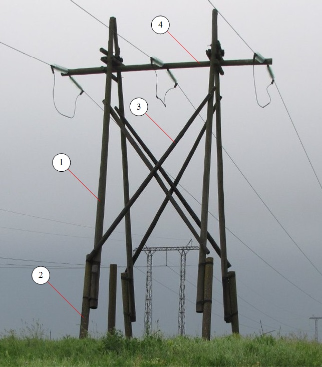
VL supports up to 1 kV. Three types of unified wooden supports are installed on overhead lines up to 1 kV: single-column (Fig. 11, a, b), single-column with struts (Fig. 11, c) and A-shaped (Fig. 11, d). Single-column supports are used as intermediate, and single-column with struts and A-shaped (so-called complex) - as corner, anchor, end and branch. Two series of such supports have been developed: for suspension of 5-8 and 8-12 wires with fastening, respectively, on hooks and pins.
Fig.11. Wooden poles for overhead lines up to 1 kV:
a, b - single-column intermediate with fastening of wires on hooks and pins,
c - single-column corner with a tray and fastening of wires on hooks,
g - A - shaped corner with fastening of wires on pins:
1 - prefix,
2 - rack,
5, 6 - traverse and its brace,
7 - support strut,
8 - crossbar
The main elements of supports of all types are racks 2, attachments 1 and struts 7. Racks and struts are made of impregnated wooden poles 6.5-11 km long with a diameter in the upper cut of at least 14 cm. To increase the service life of the supports, they are usually used standard reinforced concrete prefixes PT with a length of 4.25 and 6 m, and in some cases - wooden ones with a length of 4.5 m. Supports without prefixes (with solid racks and struts) are also installed. In soft soils, the strength of the embedment of supports is increased by fixing reinforced concrete slabs or wooden crossbars in their bases 8.
To pair (Fig. 12, a - c) wooden 3 and reinforced concrete 9 attachments with racks 1, wire bandages 2 and fitting clamps 6 are used. Bandages for single-rack supports are made of eight turns of galvanized steel wire with a diameter of 4-6 mm, and for complex ones - of 12 and are tightened by twisting or coupling bolts 5 with shaped washers 4. The length of the mating of the racks of single-column supports with wooden and reinforced concrete attachments is 1350 and 1050 mm, respectively, and complex - 1500 and 1350 mm.
Fig.12. Pairing attachments with racks of supports of overhead lines up to 10 kV:
a. b - wooden wire bandages,
c - reinforced concrete clamps;
1 - stand,
2 - wire bandage,
3, 9 - wooden and reinforced concrete attachments.
4 - bandage washer,
5 - coupling bolt,
6 - fitting collar
8 - plank
The struts with the uprights and the tops of the A - shaped supports are bolted together. Traverses are made of impregnated wood and equipped with pins and braces. Standard traverses have a rectangular section of 100x80 mm; traverses of circular cross section with a diameter of 140 mm are used only on end supports with 12 wires. The traverses are fixed to the posts with a through bolt and two braces (see Fig. 11, b).
The distance between the wires on the traverses of the intermediate supports should be 400 mm, and on the corner and anchor - 550 mm. Hooks on the supports are placed on both sides of the rack in a checkerboard pattern; at the same time, the distance between them (on one side) should be 400 and 600 mm on intermediate and complex supports, respectively. The upper hook is installed at a distance of 200 mm from the top of the support.
Supports VL 6-10 kV. On 6-10 kV overhead lines, unified free-standing wooden poles of three types are installed: single-column - intermediate; A - figurative - end, anchor, branch; three-rack (A - shaped with struts) - corner anchor. A - shaped trusses of anchor and end supports are installed along the axis of the overhead line, and angular - along the bisector of the angle of rotation of the line.
Figure 13 shows the main types of wooden poles for 6-10 kV overhead lines with reinforced concrete and wooden attachments and wire suspension on hooks and traverses. Single-column supports (Fig. 13, a) consist of a rack 2, attachment 1 and hooks 3. For hanging wires of large cross sections, instead of hooks, a traverse 6 with pins 4 and a head 5 are installed (Fig. 13, b). A - shaped and three-post supports (Fig. 13, c - e), in addition to racks and attachments, have under-traverses 9, with which the traverses are attached to the racks, as well as cross-beams 10 (reinforcing the rigidity of the A-shaped truss), crossbars 8 and struts 11. In addition, poles 11 m long without attachments (with solid racks) are installed on 6-10 kV overhead lines.
Support structure overhead lines power transmission
Support structure
The structures of overhead power transmission line poles are very diverse and depend on the material from which the pole is made (metal, reinforced concrete, wood, fiberglass), the purpose of the pole (intermediate, angular, transpositional, transitional, etc.), on local conditions on the line route ( populated or uninhabited areas, mountainous conditions, areas with swampy or soft soils, etc.), line voltages, number of circuits (single circuit, double circuit, multi circuit), etc.
In the design of many types of supports, the following elements can be found:
- Rack - is the main integral element of the support structure, unlike other elements that may be absent. The rack is designed to provide the required dimensions of the wires (wire dimension - the vertical distance from the wire in the span to the wires crossed by the route engineering structures, the surface of the earth or water). There can be one, two, three or more posts in the support structure.
- Struts - used for corner, end, anchor and branch supports of overhead lines with voltage up to 10 kV. They take on part of the load of the support from the one-sided tension of the wire.
- Attachment (stepson) - partially buried in the ground, the lower part of the structure of the combined support of overhead lines with a voltage of up to 35 kV, consisting of wooden racks and reinforced concrete attachments.
- Braces are inclined support elements that serve to reinforce its structure and connect several support elements to each other, for example, a post with a traverse, or two support posts.
- Traverse - provides fastening of the wires of the power line at a certain (permissible) distance from the support and from each other.
- Foundation - a structure embedded in the ground and transferring loads to it from the support, insulators, wires and external influences (ice, wind).
- Crossbar - increases the side surface of the underground structure of reinforced concrete racks and footboards of metal supports. Crossbars increase the ability of the foundation to withstand horizontal loads acting on the support, preventing it from tipping over from the forces of tension of the wires when constructing supports in soft soil.
- Guys - designed to increase the stability of the supports and perceive the forces from the tension of the wire.
- Rope stand - the upper part of the support, designed to support the lightning protection cable. Usually it is a trapezoidal spire at the top of the support. On the support there can be one or two cable racks (on U-shaped supports), there are also supports without a cable rack.
 |
|
| a | b |
Picture. VL supports: a - two-column support; b - three-post support.
A rack of lattice-type metal supports is called a trunk. The barrel is usually a tetrahedral truncated lattice pyramid made of rolled steel profiles (angle, strip, sheet), and consists of a belt, a lattice and a diaphragm. The lattice, in turn, has rods-braces and spacers, as well as additional connections.
Picture. Structural elements of a metal support: 1 - support post belt; 2 - rods-braces forming a rack lattice; 3 - diaphragm; 4 - traverse; 5 - cable rack.

Picture. Corner support with two struts: 1 - rack; 2 - brace.
Picture. Structural elements of the combined support: 1 - wooden support post; 2 - reinforced concrete prefix (stepson); 3 - brace; 4 - traverse.
Picture. Support traverses: a - for reinforced concrete supports 10 kV; b - for reinforced concrete supports 110 kV.
Most often you can find traverses in the form of a rigid metal structure, but there are also wooden traverses and traverses made of composite materials.
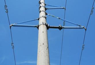
Picture. 110 kV overhead line support traverse made of composite materials
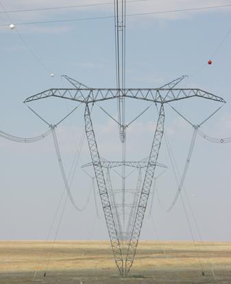
In addition, so-called flexible traverses can be found on V-shaped supports of the "nabla" type and U-shaped supports.
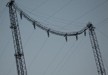
Picture. VL support with a "flexible" traverse
In some pole designs, traverses may be absent, for example, for wooden or reinforced concrete poles of overhead lines with a voltage of up to 1 kV, for poles of overhead lines with self-supporting insulated wires voltage up to 1 kV, for anchor supports of overhead lines of any voltage, where each phase is mounted on a separate rack.
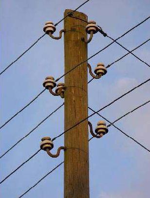
Picture. Support without traverse
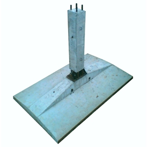
Picture. Mushroom reinforced concrete foundation
For single-rack supports, in which the lower end of the rack is embedded in the ground, the bottom of the rack serves as the foundation; for metal supports, pile or prefabricated mushroom-shaped reinforced concrete ones are used, and when installing transitional supports and supports in swamps, monolithic concrete foundations are used.
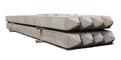
Picture. Reinforced concrete piles used in single-pile and multi-pile foundations of overhead lines
Picture. Power transmission line support on a pile foundation

Picture. Mushroom reinforced concrete foundation (1) with three crossbars (2)
Picture. Support secured with braces
The upper part of the guy is attached to the post or traverse of the support, and the lower part to the anchor or reinforced concrete slab. In addition, the design of the brace may include a tension coupling - a lanyard.
 |
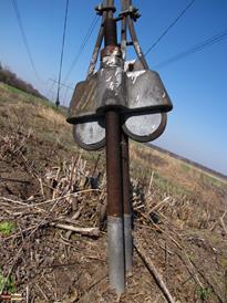 |
Picture. Lower part of the brace
|
MINISTRY OF ENERGY AND ELECTRICITY OF THE USSR NPO ENERGOSTROYPROM Special design and engineering bureau "ENERGOSTALPROEKT" |
APPROVE Chief Engineer NPO Energostroyprom ____________________ Yu.G. Zhivov "____" ______________ 1989 |
STRUCTURES STEEL SUPPORTS OF ELECTRIC TRANSMISSION LINES AND OPEN DISTRIBUTION DEVICES OF SUBSTATIONS WITH VOLTAGE 35 kV and HIGHER. Specifications TU 34 12.10057-89 (Instead of TU 34-29-100057-80) Date of introduction from 01.01.90 |
AGREED Chief Engineer of SSO Elektrosetstroy _________________V.G. Nayanov "____" ___________ 1989 | Chief Engineer of SPKTB Energostalproekt ___________________V.L. Chen "____" _______________ 1989 | Chief Engineer of the Energosetproekt Institute _________________V.S. Lyashenko "____" ___________ 1989 |
intermediate support VL 220 kV P 220-1 TU 34 12.10057-89
or cell portal outdoor switchgear 750 kV, YAZH-2 TU 34 12.10057-89.
And the number of the wiring diagram of the ordered design is indicated.
1. TECHNICAL REQUIREMENTS
1.1. The structures of overhead line supports and outdoor switchgear portals must meet the requirements of GOST 23118-78, SNiP III -18-75 and these specifications. 1.1.1. The main parameters and dimensions of the support elements and outdoor switchgear must comply with those specified in the working drawings of the KMD.1.2. Characteristics (manufacturing requirements)
1.2.1. Details and assembly units of supports and outdoor switchgear must be manufactured at the factory in the form of shipping marks in full compliance with the requirements of these technical specifications according to working drawings of KMD approved in the prescribed manner. 1.2.1.1. In the manufacture of elements, parts, and also welded assemblies from SPKS, it is necessary to be guided by the Directive, developed by the Energosetproekt Institute, DU 25/1-88. 1.2.2. The materials used for the manufacture of elements of overhead lines and open switchgear portals must comply with those specified in the projects. Steel arches must comply with the specified working drawings and be confirmed by certificates. The choice of grade and category of steel should be made according to SNiP II -23-81, depending on the area of operation. It is allowed to replace steel grades and rolled products with equal strength or higher strength according to calculation sheets. (Changed edition, Notice No. 1) When used in VL supports and portals of outdoor switchgear SPKS, the following rolled products are recommended: 1) shaped - from steel grade 08KhGSDP according to TU 14-1-4877-90; 2) sheet - from steel grades 12KhGDAF according to TU 14-1-4685-89 10KhNDP and 10KhDP according to TU 14-1-1217-75; (Changed edition, Notice No. 1) 3) sheet and shaped products from steels 10KhNDP and 15KhSND according to GOST 19281-89. (Changed edition, Notice No. 2) 1.2.3. Welding of support assemblies and outdoor switchgear, except for SPKS assemblies, should be carried out by semiautomatic devices in a carbon dioxide environment using wire according to GOST 2246-70 or flux-cored wire TU 14-4-1059-80 and TU 14-4-1117-81. Manual arc welding is allowed with electrodes of the type E42, E46, E50, E42A, E46A, E50A in accordance with GOST 9466-75 and GOST 9467-75. For welding parts and assemblies from SPKS, semi-automatic welding in a carbon dioxide environment with a wire according to TU 14-1-3665-83 or flux-cored wire PPV-5KM according to TU 36-2528-83, or manual arc welding with electrodes of the E50A type GOST 9467-75 should be used brand OZ C -18 TU 14-4-804-77. 1.2.4. To assemble the structures of supports and outdoor switchgear, fasteners should be used that correspond to those specified in the working drawings: bolts of strength classes 4.6, 4.8, 5.6, 5.8 from carbon steels and 5.6 from steel 08KhGSDP of accuracy classes A, B, C version 1 with a large thread pitch according to GOST 7798-70, GOST 7796-70, GOST 7805-70, GOST 15589-70, GOST 15591-70, TU 34 12.10413-90 and TU 14-4-1386-86; (Changed edition, Notice No. 2 ) nuts of class 4 and 5 made of carbon steels and SPKS accuracy classes A, B and C according to GOST 5915-70, GOST 5927-70 and GOST 15526-70; washers GOST 11371-78 and GOST 6402-70. 1.2.5. To protect against corrosion the structures of overhead lines and open switchgear portals, the materials specified in the projects, working drawings or orders should be used: zinc according to GOST 3640-79, aluminum not lower than grade A8 according to GOST 11069-74 or paints and varnishes according to SNiP 2.03.11-85. 1.2.6. The marking of elements of supports and outdoor switchgear should be carried out by any method that provides the required accuracy of work and economical consumption of steel, 1.2.7. Details of supports and outdoor switchgear must be made of straightened rolled products. 1.2.8. Editing of rolled products in a cold state should be carried out on rollers and presses. The surface of steel after straightening should not have dents, nicks and other damage. 1.2.9. It is allowed to use profiled rolled products with factory butt welds, provided that their strength is not lower than the strength of the main section with mandatory control of the seams. Number of joints: in waist corners - no more than three; in lattice braces - no more than one. The distance between the butt joints on the belt is at least 3000 mm. The distance between the weld and the center of the hole must be at least 100 mm. At a distance of less than 100 mm, if the reinforcement of the seam interferes with the tight mating of the elements, it must be removed. 1.2.10. Hot machining of carbon and low-alloy steel parts should be carried out after heating to a temperature of 900°-1000°C and terminated at a temperature not lower than 700°C. 1.2.11. Preparation for welding, welding and welding quality control must comply with the requirements of GOST 5264-80. GOST 6996-66, GOST 11534-75, GOST 14771-76 and SNiP III-18-75. (Changed edition, Notice No. 2) 1.2.12. The edges of the parts after oxygen cutting must be cleaned of burrs, slag, splashes and sagging of metal and not have irregularities and roughness exceeding: for machine cutting - 0.3 mm; for manual gas cutting - 1 mm. 1.2.13. The edges of the parts after cutting with scissors should not have irregularities, burrs and blockages exceeding 0.3 mm, as well as cracks. 1.2.14. Holes for bolts should be formed by punching, drilling or punching to a smaller diameter, followed by reaming to the design diameter in accordance with the indication in the working drawing. Hole punching to the design diameter is allowed: for structures operated in areas with a design temperature of minus 40 ° C and above - in ordinary quality carbon steel elements up to 20 mm thick and up to 16 mm in low alloy steel elements; (Changed edition, Notice No. 1) for structures operated in areas with a design temperature below minus 40 ° C - in elements made of carbon steel of ordinary quality up to 12 mm thick and made of low-alloy steel, except for SPKS - up to 10 mm; for structures operated in areas with design; temperature of minus 50°C and above - from mastered shaped steel 08KhGSDP up to 10 mm thick and for elements from rolled sheet steel 12KhGDAF up to 12 mm thick; for - elements of supports and outdoor switchgear operated in areas with a design temperature of minus 40 ° C and above from rolled sheet steel 12KhGDAF with a thickness of up to 16 mm; in other cases, the formation of holes in the elements must be done by drilling. 1.2.15. The nominal hole diameters for shear bolts shall be taken as 1 mm greater than the nominal diameter of the bolt shank. Hole diameter deviations must be within 0; +0.6 mm. the diameter of the punched holes on the side of the matrix should not exceed the nominal diameter by more than 0.1 of the element thickness, but not more than by 1.5 mm. When the design distance from the axis of the hole to the edge of the element is less than 1.5 of the hole diameter, the holes should be formed only by drilling. (Changed edition, Notice No. 1) 1.2.16. Permissible dimensional deviations between holes must comply with the requirements of SNiP III-18-75. 1.2.17. On the inner surface of the metal along the contour of the hole there should be no tears and delaminations of the metal. Burrs along the contour of the holes on the die side must be removed. 1.2.18. The assembly of welded structures and assemblies of supports and outdoor switchgear should be carried out in assembly jigs, ensuring the invariability of their shape and safe work. 1.2.19. The connection of parts during the assembly of welded support assemblies should be carried out; 1) by means of tacks; 2) using bolts. 1.2.20. Tacks must be placed at the locations of welds according to the manufacturer's technology and carried out with electrodes or welding wire used for welding structures. 1.2.21. Protection of support elements and outdoor switchgear against corrosion must be carried out at the factory in the form of hot-dip galvanizing (aluminizing is allowed) or paint coating in accordance with the requirements of working drawings and orders. The thickness of the protective coating must comply with the requirements of working drawings or SNiP 2.03.11-85 and GOST 9.307-89, depending on the degree of aggressiveness of the environment. (Changed edition, Notice No. 1)(Changed edition, Notice No. 2) The quality of the protective properties of the coating does not deteriorate with an increase in the thickness of the coating in excess of the nominal value. Support elements and outdoor switchgear made of SPKS do not require corrosion protection. In bolted connections, contact of structural elements made of steel grades VSt3, 09G2S, 14G2, 10G2S1, protected by zinc or aluminum coating with elements made of SPKS is allowed. 1.2.22. Bolts, nuts and washers used for assembling galvanized (aluminized) structures must be galvanized. The thickness of the coating during hot-dip galvanizing should be at least 42 microns, with galvanized - at least 12 microns. Fasteners that do not have a protective coating, except for those made of SPKS, must be subjected to conservation in accordance with the requirements of GOST 9.014-78. 1.2.23. The preparation of the surfaces of the elements and assemblies of the overhead lines and the portals of the outdoor switchgear, as well as fasteners for the application of protective coatings, must be carried out according to the technology in force at the manufacturer. 1.2.24. The service life of overhead line supports and open switchgear portals is set to be from 30 to 50 years, zinc (aluminum) coating - from 20 to 30 years, paint and varnish - from 3 to 5 years, depending on the conditions of the area where the structures are used.1.3. Completeness
1.3.1. The completeness of supports and outdoor switchgear is determined by the technical documentation of the project and drawings SC.1.3.2. Stands for them may be included in the set of supports. The stand type is specified when ordering in accordance with the technical documentation of the project. 1.3.3. Documentation attached to one address for a batch of overhead line supports or outdoor switchgear portals should consist of: assembly drawing (KMD) - 2 copies. picking list - 1 copy. certificate - 1 copy. The certificate must be made in accordance with SNiP III -18-75.1.4. Marking
1.4.1. All elements and welded assembly units and assemblies of supports and outdoor switchgear must have an assembly marking consisting of appropriate characters (alphabetic and numeric). Brands of elements must correspond to those indicated in the KMD drawings. 1.4.2. Marking shall be carried out by extrusion on presses. The imprint must be clear, with a depth of 0.6 to 1.0 mm with a character height of at least 10 mm. 1.4.3. Each package, box or welded structure (shipping element) must be affixed with a metal or other tag with a transport marking or a label made by electrographic method on sulphate paper or tracing paper. Marking on the tag can be applied in any way that ensures its safety, according to the manufacturer's technology. The tag or label must contain: 1) the brand (type, code) of the support or outdoor switchgear; 2) package number (design brand); 3) mass of the package, design It is allowed to apply the content of the marking on packages, boxes and shipping elements using a stencil with indelible paint. 1.4.4. On shipping elements and assembly units of overhead line supports and outdoor switchgear portals that are not subject to galvanization (aluminization), on welded galvanized (aluminized) large-sized units and belts from corner No. 20 and above, it is allowed to apply mounting markings with contrasting indelible paint on a stencil. The height of the signs must be at least 30 mm. It is also allowed to securely attach metal tags with mounting markings made by extrusion on presses to large-sized belts. (Changed edition, Notice No. 1)1.5. Package
1.5.1. Elements of supports and outdoor switchgear must be assembled in packages. Stacking of support elements and outdoor switchgear in packages, packaging means and fastening methods must comply with RD 34 12.057-90 and be carried out according to the manufacturer's picking list. The mass of the package is determined theoretically according to the picking lists and should not exceed 5 tons. By agreement with the customer, the mass of the package can be more than 5 tons. (Changed edition, Notice No. 2) The metal parts of the packaging of bags assembled from galvanized or aluminum elements must be galvanized, aluminized or painted. 1.5.2. Fasteners (bolts, nuts, washers) must be packed in tight wooden boxes made according to the factory's drawings in accordance with the requirements of GOST 2991-85. The weight of the box must not exceed 80 kg. By agreement with the customer, fasteners can be packed and shipped in boxes weighing more than 80 kg. It is allowed, in agreement with the customer, to pack and ship fasteners and small shipping items in reusable metal containers made in accordance with OST 14-43-80, in metal containers made from production waste according to the manufacturer's drawings, as well as in boxes, from the support belts or outdoor switchgear assembled in a package and sent to the same line. Fasteners packed in wooden boxes, reusable containers, containers, boxes or other containers must be sorted and divided according to standard sizes. The carrying capacity of reusable packaging and containers should not exceed 1000 kg, 1.5.3. Documentation is sent to the customer by mail.2. ACCEPTANCE RULES
2.1. Elements, welded assemblies and assembly units of overhead line supports and open switchgear portals must be accepted by the quality control department of the manufacturer. 2.2. Upon acceptance, the QCD must check: 1) materials according to certificates or acts of the factory laboratory; 2) compliance of parts and assembly units with the requirements of the drawings and these specifications; 3) availability of all parts, assembly units in accordance with the specification, components and shipping lists; 4) quality of welding with measurement of legs; 5) availability of documentation attached to the structures. 6) the quality of the protective coating. (Changed edition, Notice No. 1) 2.3. Before applying a protective coating in the amount of 2% of the lot, the elements of supports and outdoor switchgear should be randomly checked for compliance with their length, distance between the extreme holes, as well as compliance with the dimensions between the centers of adjacent holes with the design dimensions. After applying the protective coating, the elements of supports and switchgear, as well as fasteners, must be subjected to control appearance, coating thickness and adhesion strength to the base metal. 100% of structural elements should be subject to control of the appearance of the coating. 2.4. If during the inspection unacceptable defects in welded joints are detected, the defective sections of the welds must be removed and re-welded with a subsequent check. Correction of a defective area can be made no more than two times. 2.5. VL supports and open switchgear portals must be subjected to a control assembly for compliance with the requirements of these technical specifications and working drawings. Control assembly can be carried out both at the factory and at the installation site (picket). The control assembly should be subjected to one out of every fifty manufactured supports and at least one from each batch of less than 50 pcs. It is allowed to make a control assembly of one support from a batch of more than 50 pcs. in the event that the elements of the supports are made on the same technological equipment without readjustment. The assembly of the support can be done completely or section by section by serial connection and disconnection of checked sections or assembly of junctions of individual sections. Each first support made according to new or repaired conductors or according to design documentation, in which design changes have been made, must also be subjected to a control assembly. Open switchgear portals must be subjected to control assembly as directed by the plant's quality control department, regardless of the batch size. Based on the results of the control assembly, an act must be drawn up, signed by the management of the manufacturing workshop, the head of the Quality Control Department and the chief designer. 2.6. During the control assembly of overhead line supports and open switchgear portals, the interfaces of their elements and junctions of sections, the dimensions between the axes, the alignment of the holes of the connected elements, and the presence of mounting markings should be checked. 2.7. The consumer (customer) has the right to accept the elements and structures of supports and outdoor switchgear, while applying the acceptance rules and control methods established by these technical specifications.3. CONTROL METHODS
3.1. The quality control and relative position of the mounting holes made on the design diameter should be carried out in one of the following ways: (Changed edition, Notice No. 1) 1) checking with a measuring instrument; 2) checking with special devices or control templates; 3) visual inspection during control assemblies. (Changed edition, Notice No. 1) 3.2. Hole diameters, cutoffs, risks, distances between adjacent holes in a group can be checked with calipers according to GOST 166-89, metal rulers according to GOST 427-75. (Changed edition, Notice No. 2 ) Linear dimensions, the distance between the centers of groups of holes and between adjacent holes can be checked with tape measures in accordance with GOST 7502 -89 class 2 or with metal rulers. (Changed edition, Notice No. 2) 3.3. Quality control of welds should be carried out by: 1) systematic verification of compliance with the assembly and welding process; 2) external examination of 100% of the seams with a random check of the dimensions of the legs with cathetomers; 3) carrying out mechanical tests (at the request of the Quality Control Department). 3.4. Quality control, thickness of adhesion strength with the base metal, protective coating and control methods must comply with the requirements GOST 9.307-89, GOST 9.302-88 , OST 34-29-566-82, OST 34-29-582-82, TU 34-12-11166-87. (Changed edition, Notice No. 2)4. TRANSPORT AND STORAGE
4.1. Transportation of support elements and outdoor switchgear can be carried out by any mode of transport in compliance with established rules. 4.2. Loading, fastening and transportation of packages or welded sections of supports and outdoor switchgear on open rolling stock must be carried out in accordance with the Rules for the carriage of goods and the technical conditions for loading and securing goods approved by the Ministry of Railways, with full use of the carrying capacity of the wagons. Loading, fastening and transportation of packages and sections on road transport is carried out in accordance with the Rules for the carriage of goods by road in the RSFSR, approved by the Ministry of Road Transport of the RSFSR.4.3. Loading and unloading of packages and welded sections must be carried out in ways that exclude damage to the elements and their protective coating. 4.4. Storage of packages and welded sections should be carried out on linings. 4.5. Storage and transportation of packages and welded sections in terms of the impact of climatic environmental factors must comply with GOST 15150-69, OZHZ group.5. GUARANTEE OF THE MANUFACTURER (SUPPLIER)
5.1. The manufacturer guarantees the conformity of the VL supports and open switchgear portals to the requirements of these technical specifications, provided that the consumer observes the rules of operation, transportation and storage. 5.2. The warranty period is set for 2 years from the date of receipt of the supports B L and the portals of the outdoor switchgear by the consumer.APPENDIX
LIST of documents mentioned in TU 34.12.10057-89
|
Document designation |
Name |
GOST 9.014-76 | ESZKS. Temporary anticorrosive protection of products. General requirements | 1.2.22 | GOST 9.302-88 | ESZKS. Metallic and non-metallic inorganic coatings o Acceptance rules and control methods | 3.4 | GOST 9.307-89 | ESZKS. Hot zinc coatings. General requirements and methods of control | 3.4 | GOST 166-89 | Calipers. Specifications | 3.2 | GOST 427-75 | Metal measuring rulers. Specifications | 3.2 | GOST 2246-70 | Wire steel welding. Specifications | 1.2.3 | GOST 2991-85 | Wooden non-separable boxes for loads weighing up to 500 kg. General specifications | 1.5.2 | GOST 3640-79 | Zinc. Specifications | 1.2.5 | GOST 5264-80 | Manual arc welding. Connections are welded. Main types of structural elements and dimensions | 1.2.11 | GOST 5915-70 | Hexagon nuts of accuracy class B. Design and dimensions | 1.2.4 | GOST 5927-70 | Hexagon nuts of accuracy class A. Design and dimensions | 1.2.4 |
|
Document designation |
Name |
Specification item number |
GOST 6402-70. | Spring washers. Specifications | 1.2.4 | GOST 6996-86 | Welded connections. Methods for determining mechanical properties | 1.2.11 | GOST 7502-80 | Roulettes measuring metal. Specifications | 3.2 | GOST 7796-70 | Reduced hexagon head bolts, accuracy class B. Design and dimensions | 1.2.4 | GOST 7798-70 | Hexagon head bolts of accuracy class B. Design and dimensions | 1.2.4 | GOST 7805-70 | Hexagon head bolts, accuracy class A. Design and dimensions | 1.2.4 | GOST 9466-75 | Coated metal electrodes for manual arc welding of steels and surfacing. Classification, dimensions and general technical requirements. | 1.2.3 | GOST 9467-75 | Coated metal electrodes for manual arc welding of structural and heat-resistant steels. Types | 1.2.3 | GOST 11069-74 | Aluminum primary. Stamps | 1.2.5 | GOST 11371-78 | Washers. Specifications. | 1.2.4 | GOST 11534-75 | Manual arc welding. Connections are welded at acute and obtuse angles. Basic types, structural elements and dimensions. | 1.2.11 | GOST 14771-76 | Arc welding in shielding gas. Connections are welded. Main types, structural elements and dimensions | 1.2.11 . |
|
Document designation |
Name |
Specification item number |
| GOST 15150-69 | Machines, devices and other technical products. Versions for different climatic regions. Categories, operating conditions, storage and transportation in terms of the impact of climatic environmental factors. | |
| GOST 15526-70 | Hexagon nuts of accuracy class C. Design and dimensions | |
| GOST 15589-70 | Hexagon head bolts of accuracy class C. Design and dimensions | |
| GOST 15591-70 | Reduced hexagon head bolts of accuracy class C. Design and dimensions | |
| GOST 19281-89 | Rolled steel of increased strength. General specifications | |
| GOST 23118-78 | Metal building structures. General specifications. | |
| TU 34 12.10413-89 | Bolts are special. | |
| OST 34-29-566-82 | Protective coating of fasteners of steel structures of overhead power transmission lines (VL) and open switchgear (OSG) of high-voltage substations by hot-dip galvanizing. Technical requirements. Acceptance rules and control methods | |
| OST 34-29-582-82 | Protective coating of fasteners of steel structures of overhead power transmission lines (VL) and open switchgear (OSG) of high-voltage substations by hot-dip galvanizing. Technical requirements. Acceptance rules and control methods |
|
Document designation |
Name |
Specification item number |
| SNiP 2.03.11-85 | Building codes and regulations Protection of building structures against corrosion, |
1.2.11 , 1.2.5 , 1.2.2 3 |
| SNiP III-18-75 | Rules for the production and acceptance of work. Metal constructions |
1.1, 1.2.11 , 1.2.16, 1.3.3 |
| SNiP II-23-81 | Rules for the production and acceptance of work. Metal constructions | |
| TU 14-1-1217-75 | Low-alloy sheet steel grades 10HNDP and 10KhDP |
Introduction, 1.2.2 |
| TU 14-1-3665-83 | Welding wire brand Sv-08G2SDYU | |
| TU 14-1-4877-90 | rental |
Introduction, 1.2.2 |
| TU 14-1-4685-89 | Rolled sheet from low-alloyed steel grade 12HGDAF. |
Introduction, 1.2.2 |
| TU 14-4-804-77 | OZC-I8 brand electrodes | |
| TU 14-4-1059-80 | Cored wire PP-AN8 | |
| TU 14-4-1117-8 I | Cored wire PP-AN22 | |
| TU 14-4-1386-86 | Bolts of special accuracy class B | |
| TU 34 12.11166-87 | Structural elements of steel poles of overhead power transmission lines (OL) and open switchgears (ORG) of high-voltage substations with a protective coating applied by hot aluminizing | |
| TU 36-2528-83 | Cored wire PPV-5K | GOST 4.332-85 System of product quality indicators. Fire fighting vehicles. Nomenclature of indicators
We advise you to read
 Psychological characteristics of children in adolescence
 Transferring a child to another school - the procedure and necessary documents Whether to transfer a child to another school
, diagnosis, treatment Treatment of urogenital chlamydia") Chlamydia urogenital - description, causes, symptoms (signs), diagnosis, treatment Treatment of urogenital chlamydia
Chlamydia urogenital - description, causes, symptoms (signs), diagnosis, treatment Treatment of urogenital chlamydia The benefits and significance of hydroamino acid threonine for the human body L threonine what

