Attention new! Voltage stabilizer for the whole house SKAT ST-12345 is designed specifically for networks with unstable mains voltage. Stabilizes the voltage in the range from 125 to 290 Volts! It has a large power of 12 kVA! Warranty - 5 years! Watch the stabilizer test video.
High and high voltage. Causes
How can a high or increased voltage appear in our electrical networks? voltage. As a rule, low-quality Electricity of the net or network failures. The disadvantages of networks include: outdated networks, low-quality network maintenance, a high percentage of depreciation of electrical equipment, inefficient planning of transmission lines and distribution stations, and an uncontrolled increase in the number of consumers. This leads to the fact that hundreds of thousands of consumers receive high or increased voltage. The voltage value in such networks can reach 260, 280, 300 and even 380 Volts.
Smart systems and customized energy efficient lighting are great. candidates for low voltage wiring. Installing a low voltage line for these lights means fewer conversions in your home. Likewise, creating smart home uses several. digital devices. Installing low voltage circuits to meet these requirements might be a bad idea depending on how many. chains you need.
Not sure if you are working on low or high voltage? We'll take a look at your stress and we'll even help you with your current project if you'd like! For getting additional information about home and business electrical inspections visit. It depends on the function of the circuit!
One of the reasons for the increased, oddly enough, may be the reduced voltage of consumers located far from transformer substation. In this case, electricians often deliberately increase the output voltage of the electrical substation in order to achieve satisfactory current indicators for the last consumers in the transmission line. As a result, the voltage in the first line will be increased. For the same reason, one can observe increased tension in holiday villages. Here, the change in current parameters is associated with seasonality and frequency of current consumption. In summer, we observe an increase in electricity consumption. During this season, there are a lot of people in the dachas, they use a large amount of energy, and in winter the current consumption drops sharply. Weekend consumption summer cottages rises and falls on weekdays. As a result, we have a picture of uneven energy consumption. In this case, if you set the output voltage at the substation (and they are usually not of sufficient power) to normal (220 Volts), then in the summer and at the output the voltage will drop sharply and will be reduced. Therefore, electricians initially set up the transformer for increased voltage. As a result, in winter and on working days, the voltage in the settlements is high or increased.
These different voltages are achieved with resistors from the main power line in series to a specific point in the circuit. If you know that the current being measured is measured by a specific point in the circuit, the required voltage at the point, and the supply voltage, the series resistor value is calculated using Ohm's Law using the required voltage drop across the resistor.
If a part of a circuit draws a different amount of current in operation due to its design - for example, driving a motor with a varying load such as a model tank going uphill - the voltage drop caused by the resistor will increase as the load increases, the components will receive a lower voltage than you expected. This can have various effects such as power, instability, or simply the circuit simply refusing to function.
The second large group of reasons for the appearance of high voltage is phase imbalances when consumers are connected. It often happens that consumers are connected randomly, without a preliminary plan and project. Or, in the course of project implementation or development of settlements, there is a change in the value of consumption in different phases of the transmission line. This can lead to the fact that on one phase the voltage will be reduced, and on the other phase it will be increased.
In this case, some sort of voltage adjustment is required towards the bottom of the voltage circuit. For getting constant voltage are used various methods. An in-line resistor operating on a zener diode at the point of interest is one way. There are integrated voltage regulators available with two terminals in series supplied, which runs up to the point of interest, and a third terminal connected to the reference point, usually the negative power line.
The problem with any types of series resistors and voltage regulator ICs is that the current flowing through the resistor generates heat. If the current is in the milliamp range with resistance in the thousands of ohms, this heat is negligible. In higher power circuits, heat becomes a problem and must be removed by heatsinks or fans.
The third group of causes of increased voltage in the network is accidents on power lines and internal lines. Two main reasons should be distinguished here - a zero break and the ingress of high voltage current into ordinary networks. The second case is a rarity, it happens in cities in strong wind, Hurricane. It happens that the power line of an electric transport (tram or trolley bus) falls into the lines of city networks during a break. In this case, both 300 and 400 volts can get into the network.
Now let's consider what happens when the "zero" disappears in the internal house networks. This case happens quite often. If two phases are used in one entrance of the house, then when zero disappears (for example, there is no contact at zero), the voltage value changes on different phases. In the phase where now the load in the apartments is less, the voltage will be overestimated, in the second phase it will be underestimated. Moreover, the voltage is distributed inversely with the load. So if on one phase the load at this moment is 10 times greater than on the other, then we can get 30 Volts (low voltage) in the first phase, and 300 Volts in the second phase ( high voltage). What will cause combustion electrical appliances and possibly a fire.
In battery-powered equipment, much of the battery capacity, and therefore battery life, is lost to heat. To solve the problem of energy loss, another solution is required. When the capacitor is charged to the required voltage, the pulses are stopped until the voltage drops very slightly below the required voltage due to the current drawn from it, which restarts the pulses and thus holds the capacitor. This is called the "dollar" circuit because the "bucks" voltage, that is, supplies the supply voltage.
What is dangerous high and high voltage
High voltage is dangerous for electrical appliances. A significant increase in voltage can lead to the combustion of devices, their overheating, additional wear. Electronic equipment and electromechanical devices are especially critical to high voltage.

Such a circuit could use the convolutional magnetic field of the inductor to boost the voltage going to the load capacitor to a higher voltage, or even reverse the polarity of the output voltage. This means that the circuit can use a lower voltage, but a higher overall battery capacity.
The advantage of balancing series regulators is that when properly designed, they lose very little energy as heat, meaning they can operate without large heatsinks and fans. Gain controls have the added benefit that they can boost voltage. Thus, it is possible to change the original circuit design of the circuit to deliver a higher voltage to the part of the circuit with low current, with the high current section connected directly to the power source.
Increased voltage can lead to a fire in the house, causing great damage.
When it comes to reducing the voltage in the network, then finding the problem is more difficult, since it depends on the type of electricity consumer used. There are two main types of consumers: resistance and motor.
For high current applications, a technique called pulse width modulation can be used. In this case, the voltage does not decrease, but the current flows in very short pulses. The width of the individual pulses is chosen so that the average current is what you would get at a lower voltage. This type of pulse width control is often used in applications such as speed control and backlight brightness.
When a relatively high input of 24V or more needs to be very finely adjusted to a much lower voltage, such as 3V or less, with very low quiescent current, there is no available ready solution. For example, if you need to efficiently drive a low power microcontroller from a 24 or 48 volt battery, you usually need two cascaded regulators. And the quiescent current is likely to be greater than the load current.
As for the consumer of the resistance type, then for them the voltage drop is directly proportional to the drop in the consumed current (s-n Ohm l \u003d U / R). For fuses, low current does not pose any danger. If we take a resistance that consumes 300 W (Fig. 55.2) at 240 V, then at a voltage of 24 V it will consume only 3 W.
As for the type of engine, it is first necessary to distinguish them by the action of a larger moment of resistance (Fig. 55.3). So, you can compare piston (larger moment of resistance? And drive motors (smaller moment of resistance?.
The simple low cost circuit shown in the figure will operate at 75µA. Less accurate estimates are also available at a lower cost. This can be done much more if a slower dial-up is desired, though. It would also limit the current in the event of a short output. What can cause such increased electrical pressure? We unplugged the electric heating pad, and then we unplugged the clip-on lamp attached to the headboard.
The lesson is that electrical devices connected to the bed cause electrical stress whether they are turned on or not, and some, perhaps all people are sensitive to this pressure. Water pressure is present on the faucet even when the faucet is turned off. Similarly, an electrical system and electrical devices connected to it cause electrical pressure even when the devices are not turned on.
![]()
Regarding centrifugal fans, they are between these two categories. Mostly their characteristics do not withstand a significant drop in supply voltage, and therefore they are classified as devices with a large moment of resistance.
You can take a small tool known as a voltage gauge and move it to the lamp inserted next to the bed. The voltage sensor will start beeping when it gets close to the lamp, whether the lamp is off or not. The voltage gauge indicates the invisible pressure coming from the off lamp.
Your body acts like an antenna in bed. Stress affects your body from everything locked up next to your bed, as well as overhead lights and wiring in the wall. The stress also affects your body from nearby metal, which can act as an antenna on your bed. For example, a metal frame can act as an antenna and increase tension on your body.
Recall that the ability of the motor to drive the device (shaft torque) depends on the square of the supply voltage. That is, if it is designed to operate on a 220 V supply, and the voltage drops to 110 V, then the torque will decrease by 4 times (Fig. 55.4). If the moment of resistance is too high when the voltage drops, the motor will stop. In this case, the current consumed by the motor will be equal to the starting current, which it will consume during a forced stop. At this moment, only the built-in protection (thermal relay) can save it from severe overheating, which will quickly turn off the power.
Why does stress affect your body? The body's communication system is the nervous system, and the signals that travel up and down the nerves and to the organs and cells are electrical. If electrical signals enter your body from outside, they can affect your body different ways. Perhaps exposure to excess voltage knocks out your immune system down the stairs without knowing it.
While there is no guarantee that you will notice any improvement the first night you sleep with reduced tension, remember that reducing body tension to zero is good and that your body is likely to experience beneficial long-term effects. In some reports, the dream reappears or with more vivid dreams.
![]()
When the drive torque is low, lowering the voltage will cause the rotation speed to decrease because the motor has less available power. This property is widely used in most multi-speed motors that rotate air conditioner fans (Fig. 55.5). When switching to BS (high speed), the resistance is short-circuited and the motor is powered from 220 V. Its rotation speed is nominal.
How can I measure and reduce body tension in my bed? You will need simple materials. 5-6 stainless steel, copper or iron pipe from the plumbing section of a home improvement store is the minimum cost.
- Grounding cord.
- If your bed has a metal frame, order 2 ground cords.
Note: You can take these measurements with the person lying on the bed. The fabric will attract tension in the same way as the body. The numbers won't be accurate, but they won't be accurate anyway, so the body substitute will work for our measuring purposes. You can always lie down or have someone else lie down on the bed to get the actual numbers.
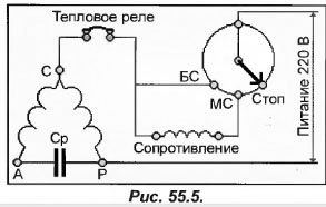
When switching to MC (low speed), the resistance is connected in series with the motor winding, due to which the voltage across it decreases. Accordingly, the torque on the shaft also decreases, so the fan starts to rotate at a reduced speed. The current consumption becomes smaller. This property is widely used in the manufacture of electronic speed controllers (based on thyristors), which are used to control the condensation pressure by changing the speed of rotation of fans in air condensers (Fig. 55.6).
Your figures with conductive cloth will probably be less than those of an actual person lying on the bed. You must have a proper working 3-hole socket to follow these instructions. If your house is older and you only have 2-hole holes, you can also take these measurements, but you can't use your outlets. Do not use any outlet in this exercise that is not wired correctly or has only 2 holes. Once you have identified a properly wired 3-hole socket, you can use it for this exercise. Place a 2-foot piece of conductive cloth on the bed where the person will be sleeping or someone else is in bed. Your goal will be to measure the voltage across one piece of conductive fabric compared to the voltage in the ground. To do this, there should be a wire of conductive fabric to ground, with a meter between them to read voltage differences. Now take your voltmeter and observe the two wires that come from it. One pin is red and the other is black. The red wire goes to the conductive fabric on the bed and the black wire is grounded to ground. First, let's make a red acquaintance. Using one set of alligator clips, connect the metal end of the red wire to a piece of metal pipe. Metal must touch metal. Place metal pipe on conductive tissue. Then place the black wire. Attach the alligator clip to the metal end of the black wire. Plug the dummy plug into a properly wired 3-hole socket. The plug is a "dummy" because only the ground pin goes into the socket. The other two prongs do not come into contact with live wires. Their sole purpose is to hold the ground pin. The ground spike connects to your home's electrical ground system. The electrical earthing system is in contact with earth. If you don't have a properly wired 3-hole socket, or if your bedroom only has 2-hole sockets, you'll have to use an alligator clip kit to attach the long wire to the black wire, skip the longer pull out the window, extend the long wire to the ground and attach it with another set of crocodile clips to the metal part of the screwdriver placed in the mud. Instead of using the grounding system at home, you will actually ground your installation directly to the ground. If the dirt is dry, pour a glass of water around the screwdriver to improve conductivity. Okay, now you should have the correct setup. The red wire goes to the replacement body and the black wire is grounded to ground. It's time to see what your body's tension is. Turn on the body voltage meter, with the setting set to "2 V.". If the reading is greater than 2V, go up to the next higher setting. Select the 2 volt setting if you have a choice. If the reading is greater than 2V, raise the dial to the next higher setting. Since we want to go down to 20 mV or less, we will speak in terms of millivolts, not volts. Move the decimal point 3 places to the right to read millivolts. Look at the units after this number. They can be millivolts, in which case just write that number down. Or they can be in volts and then mentally move the decimal point over three places to the right. For example, suppose your reading is 749V, then you should write 749mV. All of our conversations will be in millivolts, although an electrician will be more accustomed to talking about volts. Sometimes the levels are much higher. Now let's see what preliminary steps you can take to reduce your numbers. Ideally, we want a reading of less than 20 mV.
- Most houses have 3 openings in the bedrooms.
- An electrician must be called to repair any faulty outlets.
These regulators, called current converters or valves, function like other limiting regulators, working on the principle of "cutting off" the frequency of the alternating current amplitude.
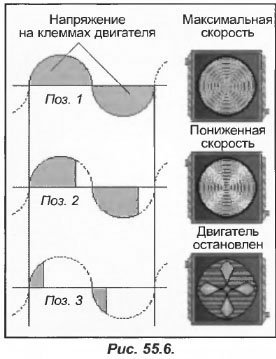
In the first position, the pressure is high and the speed controller completely skips the mains half cycles. At the motor terminals, the voltage (shaded area) corresponds to the mains supply, and it starts to rotate at maximum speed, while consuming the rated current.

In the second position, the condensing pressure begins to decrease. It enters the regulator, cutting off a part of each half-cycle entering the engine input. The voltage at the motor terminals decreases, along with the speed and current draw.
In the third position, the tension is too weak. Since the motor torque is less than the fan resistance torque, it stops and starts to heat up. Thus, the speed controllers are mainly adjusted to the maximum allowable value of the minimum speed.
In addition, the "cutting" method can be applied in single-phase motors when used for drives with low resistive torque. Concerning three-phase motors(used to drive machines with great resistance), it is recommended to use multi-speed motors, motors direct current or frequency converters.
AT Everyday life We often have to deal with voltage drops. It can be caused by a momentary shutdown or a sudden drop in current. In order to limit the voltage drop, it is necessary to correctly select the cross-section of the supply wires. But in some cases, a decrease in the voltage level is not due to a decrease in power in the supply wires.

For example, let's take a 24 V electromagnet coil that controls a small contactor (Fig. 55.7). When the electromagnet is triggered, it consumes a current equal to 3 A, and when held, it is 0.3 A (10 times less). In other words, the connected electromagnet draws a current equal to ten times the holding current. Although the turn-on time is short (20 ms), this factor can have an effect in large command circuits with a large number of contactors and relays.
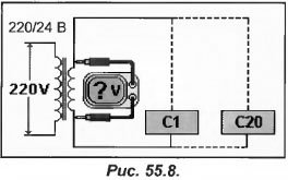
In the presented diagram (Fig. 55.8), 20 contactors are installed - C1-C20. As soon as the current is turned off, they are all in standby mode, and when turned on, they work simultaneously. When activated, each contactor consumes 3 A, which means that a current of 3 × 20 = 60 A will flow through the secondary winding of the transformer. If the resistance of the secondary winding is 0.3 Ohm, then the voltage drop on it when the contactors are activated will be 0.3 × 60=18 V. Since the voltage of the contactors reaches only 6 V, they will not be able to work (Fig. 55.9).
In this case, the transformer, together with the wiring, will overheat greatly, and the contactors themselves will hum. And this will continue until the circuit breaker trips or the fuse blows.
If the resistance of the secondary winding of the transformer is 0.2 Ohm, then when the contactors are turned on, the voltage in it will be 0.2 × 60 = 12 V. In this case, the contactors will be powered from 12 V instead of 24 V, and there is no chance that they will turn on. Their work will be similar to kA in the previous example, since the voltage in the network is abnormally high.
Difficulties with resistance secondary winding are explained by the significant open-circuit voltage at the output of the transformer, in contrast to the voltage under load. As the current draw increases, the output voltage decreases.
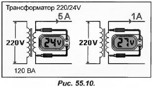
As an example, consider a 220/24 transformer (Fig. 55.10) with a power of 120 VA connected to a 220 V network. If the transformer produces a current of 5 A, then the output voltage will be 24 V (24 × 5 \u003d 120 VA). But when the current consumption drops to 1 A, the output voltage becomes large, for example, 27 V. This is provoked by the resistance of the secondary winding wire.
As soon as the current starts to decrease, the output voltage rises. And the reverse situation: as soon as the consumed current becomes more than 5 A, the output voltage decreases to 24 V, as a result of which the transformer overheats.
If the transformer is of low power, then certain difficulties may arise, so the selection of the power of the transformer should not be neglected.
We advise you to read
, diagnosis, treatment Treatment of urogenital chlamydia") Chlamydia urogenital - description, causes, symptoms (signs), diagnosis, treatment Treatment of urogenital chlamydia
Chlamydia urogenital - description, causes, symptoms (signs), diagnosis, treatment Treatment of urogenital chlamydia The benefits and significance of hydroamino acid threonine for the human body L threonine what
 To wait or not to wait for a guy from the army For what reason can they be commissioned from the army
 Baked apples with cottage cheese Baked apples with cottage cheese

