Page 1
supports contact network connected to the rails are carried by a crane along with the rail links.
Contact network supports are installed, as a rule, between tracks with a width of 6500 mm.
Contact network supports, traffic light masts, trusses of metal and reinforced concrete bridges and other similar structures, connected to the rails tightly or through spark gaps, are installed on stone, concrete or reinforced concrete foundations that ensure compliance with the established standards for the permissible leakage current.
Contact network supports, depending on their purpose, are divided into supporting, anchor, fixing and feeder.
Contact network supports are reinforced concrete, metal and wooden. The most widely used in the USSR are reinforced concrete poles, the use of which significantly reduces the consumption of metal required for the manufacture of poles. In addition, reinforced concrete poles are more economical in operation, since they do not require periodic painting, which is necessary for metal poles in order to protect them from corrosion. Installation reinforced concrete supports more difficult than metal ones, since reinforced concrete supports are much heavier and require more careful handling during transportation and installation due to the fragility of the top layer of concrete.
Supports of the contact network on railways ah the USSR used metal or reinforced concrete. Metal supports are more often used for fixing contact suspension on flexible crossbars, as well as for anchor sections. According to their purpose, the supports are divided into support (cantilever, for flexible and rigid crossbars), anchor and feeder, used to suspend supply and suction lines. The distance from the axis of the extreme track to the inner edge of the supports on the hauls and stations must be at least 3100 mm.
Contact network supports installed on the border of air gaps must have a distinctive color.
Contact network supports installed at the boundaries of air gaps must have a distinctive color. Between these supports, it is prohibited to stop the electric rolling stock with the pantograph raised.
Contact network supports that limit air gaps must have a distinctive sign - alternating four black and three white horizontal stripes.
Contact network supports, depending on their purpose, are divided into supporting, anchor, fixing and feeder. Supporting supports according to the type of supporting device attached to them are divided into cantilever (Fig. 100, a), for flexible (Fig. 100, b) and rigid (Fig. 100, c) crossbars. Cantilever supports are widely used on single-track and double-track hauls, as well as on separately located station tracks. Supports that support only one contact suspension are called intermediate. Anchor supports are designed to absorb loads from the anchored wires, and fixing supports are designed to take the forces that occur when the direction of the wires changes. Fixing supports are installed in places where, in the absence of supporting supports, it is necessary to fix the position of the wires relative to the pantograph axis. Feeder supports are called supports, on which wires of supply and suction lines are suspended.
Contact network supports are reinforced concrete and metal. Reinforced concrete supports are used more often, since there is less metal consumption on them. But it is more difficult to install reinforced concrete supports than metal ones, since they are much heavier and require more careful handling during transportation and installation due to the fragility of the top layer of concrete. Reinforced concrete supports are made of string-conical conical from centrifuged reinforced concrete (type SK with a length of 13 6; 12 8 and 11 2 m), string-concrete I-beams from vibrated reinforced concrete (type SD) and I-beams from vibrated reinforced concrete with prestressed reinforcement of steel strands. Metal - - personal supports are made in the form of tetrahedral pyramidal trusses.
Contact network supports are installed at a distance of 3100 mm from the track axis. In the recesses, they should be outside the cuvettes. In recesses heavily covered with snow (except for rocky ones) and at the exits from them, over a length of 100 m, the distance from the axis of the extreme path to the inner edge of the supports is taken to be at least 5700 mm. The list of such places is determined by the head of the road. On existing electrified lines, as well as in particularly difficult conditions on newly electrified sections of roads, contact network supports can be located at a distance of at least 2450 mm from the track axis within stations and at least 2750 mm on hauls. In this case, the horizontal distance to the foundations of the supports can be reduced accordingly.
The contact network is a rather complex structure of electrified railways.
Supports of the contact network of railways, supply the load from the wires and installed auxiliary equipment. Structures that serve as fixers for fixing and supporting devices are part of the support. The network transmits electricity from traction substations through pantographs. The current is supplied through electrical equipment, which, for example, is represented by the company "Electropostavki". The main components of the contact network are wires, reinforcing wire, carrying cable, consoles and clamps, support devices, fittings, insulators.
The railway power supply system is:
The external part (power plants, transformers, hoists, power lines), it raises and lowers the voltage;
Traction part (traction substations).
Stations, contact network are divided into groups, isolated sections - these are direct and alternating current, switchable sections.
Contact networks, depending on the purpose, are: anchor, cantilever and fixing, intermediate.
According to the types of construction, the supports are classified into: solid (without foundation), separate and removable.
There are three types of railway contact network supports:
Reinforced concrete;
metal;
Wooden.
1. Reinforced concrete racks have found application in the construction of the carrier, carrying the main contact network, on electrified railway sections. Used for: brackets, consoles and rigid crossbeams. The peculiarity of these designs is that these racks are made with the accuracy of the side surface, in the form of an annular section. With the use of longitudinal prestressed and transversely non-stressed reinforcement, a frame is made. Racks are made with parallel holes, which are located at a distance and are determined by GOST, they also serve for mounting, bracket, console and ventilation. Foundation posts, which have a special steel shoe with appropriate mounting holes, are designed for anchoring. Support that does not have additional elements fastening to the foundation, then it can be installed in a drilled cylindrical pit. The underground surface of the product is protected by a special bituminous primer. The side surface is marked with a special indelible paint. Materials and conditions of use, racks, are indicated by letters and numbers.
2. Metal supports are used as transitional, intermediate, anchor, cantilever elements and serve to distribute the load of the contact network in areas with alternating current. Such supports are used in the construction of contact network lines along railways. Thanks to hot-dip galvanizing, the structure carries a very significant power load and can last more than five years. GOST defines the marking, which consists of four characters. These metal racks are more and more often used than reinforced concrete ones. This is due to the fact that the installation speed is higher, due to the significantly lower weight, it is not necessary to use expensive cranes for installation, there are no disposal problems, which also differs from reinforced concrete supports.
3. Wooden supports, they are meant to be temporary.
Improving the supports, the contact network, is aimed at increasing its reliability, then the cost of operation and construction is reduced.
Reinforced concrete supports and foundations of metal supports are made with protection against electrocorrosive effects on their reinforcement, since stray current passes there.
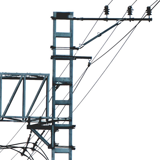
Contact network supports- structures for fixing the supporting and fixing devices of the contact networkperceiving the load from the wires. Depending on the type of supporting device, the contact network supports are divided into cantilever (with single-track or double-track consoles), racks of rigid crossbars (single or paired), supports of flexible crossbars and feeder ones (with brackets only for supply and suction wires). Supports on which there are no supporting, but there are fixing devices, are called fixing.
Reinforced concrete inseparable support of the contact network
Cantilever supports are divided into intermediate - for fastening one contact suspension, transitional, installed at the junctions of anchor sections - for fastening two contact suspensions and anchor, perceiving forces from anchoring wires. As a rule, contact network supports perform several functions simultaneously. For example, the support of a flexible crossbar can be anchored, consoles can be hung on racks of a rigid crossbar. On the supports of the contact network, brackets for reinforcing and other wires can be fixed.
Contact network supports are made of reinforced concrete, metal (steel) and wood. On domestic railways, they mainly use supports made of prestressed reinforced concrete, conical centrifuged, standard length 10.8; 13.6; 15.6 m. Metal supports of the contact network are usually installed in cases where it is impossible to use reinforced concrete in terms of bearing capacity or size (for example, in flexible crossbars). Wooden supports of the contact network are used in rare cases only as temporary ones. For plots direct current reinforced concrete poles of the contact network are made with additional rod reinforcement located in the foundation part of the poles, designed to extend their service life and reduce damage to the pole reinforcement by electrocorrosion caused by stray currents.
Depending on the installation methods, reinforced concrete supports of the contact network and racks of rigid crossbars are separate, installed in glass reinforced concrete foundations, and inseparable, installed directly into the ground. The required stability of the inseparable supports of the contact network in the ground is ensured by the installation of one upper bed or base plate.
In most cases, inseparable supports are used; separate ones are used in case of insufficient stability of inseparable supports, as well as in the presence of ground water, making it difficult to install inseparable supports of the contact network.
In anchor reinforced concrete supports of the contact network, braces are used, which are installed along the path at an angle of 45 ° and attached to the anchors.
For separate supports of the contact network, reinforced concrete foundations and anchors are used. The foundations in the above-ground part have a cup 1.2 m deep for installing a contact network support in it, followed by sealing the sinuses of the cup with cement mortar. Foundations and anchors are buried in the ground mainly by vibration immersion.
The metal supports of the contact network of flexible crossbars are usually made of a tetrahedral pyramidal shape with a standard length of 15 and 20 m.
In areas with increased atmospheric corrosion, metal cantilever supports 9.6 and 11.6 m long are installed. Metal supports are fixed in the ground on foundations. The cantilever supports of the contact network are installed on prismatic or three-beam foundations, and the supports of flexible crossbars are fixed either on separate reinforced concrete blocks or on pile foundations with grillages. The bases of the metal supports of the contact network are connected to the foundations with anchor bolts.
To fix the supports in rocky soils, in heaving soils of areas of permafrost and deep seasonal freezing, in weak and swampy soils, etc., special foundation designs are used.
Page 24 of 35
supporting structures. To maintain the wires of the contact network at a certain height and in the desired position relative to the path, consoles, flexible and rigid crossbars are intended. Consoles are installed on hauls or separate tracks of stations. They provide mechanical independence of the operation of catenary hangers of different paths and are the most economical design of those listed. Rigid and flexible crossbars are installed at stations and multi-track lines, covering up to eight tracks. These designs link mechanically contact suspensions of various ways; if they are damaged, the operation of all paths may be disrupted, which is a disadvantage of such structures.
Consoles are single-track, double-track and multi-track, and in shape - straight and inclined. Inclined consoles (Fig. 91, a) can only be single-track. Their advantage is the need for a lower support height than with a straight console (Fig. 91, b). Straight consoles are easier to manufacture, so when the height of the supports is sufficient, they are installed.
More convenient in operation are isolated rotary consoles (Fig. 91, c), in which the insulators are cut into the rod and into the console strut. With such consoles, it is possible to carry out work without removing the voltage in the places where the wires of the chain suspension are attached to them. The height of the supports with isolated consoles is reduced. When placing supports with inside curve set consoles with reverse locking posts (Fig. 91, d). Consoles with a straight locking post (dashed lines) are used on supports in recesses and behind ditches at a distance from the front face of the supports to the track axis (dimensions) of 4.9 and 5.7 m. Double-track consoles (Fig. 91, e) are made straight with two rods and a fixing stand for attaching the second track fixer. Such consoles are installed on supports 13 m high.
Consoles are made of angle or channel steel, and insulated ones are made of pipes. On the field side, consoles are placed on the supports, on which reinforcing and supply wires, overhead lines 6 (10) kV of longitudinal power supply, and DPR lines are suspended.
Rice. 91. Schemes for the design of consoles:
1 - support: 2 - console; 3 - latch; 4 and 5 - console, respectively, with a straight and reverse rack; 6 - double-track console; 7 - fixing post
Consoles are designated by letters: inclined uninsulated from two channels HP (inclined, stretched traction) or HC (compressed traction), from a pipe NTR and NTS (tubular); isolated ITR or ITS (isolated), and from channels IR or IS.
Flexible crossbars are a system of cables stretched between supports installed on both sides of the track (Fig. 92). The transverse carrying cable 2 takes all the vertical loads from the chain hangers and the self-weight of the cross member. It is made of two, three or four cables: a break in one of them does not lead to the destruction of the cross member. The upper fixing cable 1 fixes the position of the carrier cable, and the lower fixing cable 6 fixes the position of the contact wire of the chain suspension relative to the track axis. 
Rice. 92. Flexible cross member (in brackets are the dimensions for DC sections, without brackets - for alternating current)
They perceive horizontal loads acting on wires from wind, wire breaks in curves and anchorage bends. Fixation of contact wires is carried out by a latch mounted on the lower fixing cable. Depending on the number of blocked tracks, the height of the supports of the flexible cross members is 15 and 20 m.
Insulators 4 are cut into all cables at the supports, and two insulators are cut into the lower fixing one on each side with a short insert 5 between them. These inserts 1 m long are connected by electrical connectors 3 with the upper fixing and transverse support cables. As a result, a neutral insert 5 is formed, which, if necessary, can be connected to contact suspensions or to grounded supports. Such a
the connection allows you to carry out work without removing the voltage from the contact network on the hangers, flexible crossbar and wipe the insulators on it. To section the contact network, an insulator 7 is cut into the lower fixing cable in the corresponding distance.
On some sections of the road, uninsulated flexible crossbars are used, in which only the lower fixing cable is insulated. For the production of repair work on the upper fixing and transverse carrier cables, it is necessary to remove the voltage from the contact network, which is associated with stopping the movement of trains.
Rigid crossbars are metal trusses (crossbars) mounted on two posts located on both sides of the tracks (Fig. 93). As racks, string-concrete conical supports are used, which are embedded directly into the ground or installed on foundations. 
Rice. 93. Rigid crossbar:
1 - crossbar; 2 - string; 3 - latch
When anchoring wires on racks of rigid crossbars, braces are used, located along the path.
Fixation of contact wires is carried out by clamps mounted on a fixing cable stretched between posts, or fixing posts are used for this purpose. To increase the number of blocked paths, one or two consoles are installed on the racks.
The length of the crossbars is taken from 16.1 to 44.2 m and they are assembled from several blocks.
The crossbars are denoted by the letter P with numbers. For example, P13-17.7 - the first digits indicate the bearing capacity of the crossbar (in tf-m), the second - the estimated span (in m). Crossbars with a length of more than 29.1 m, on which searchlights are installed to illuminate the station tracks, are designated OP29-ZOD
Rigid crossbars are simpler in design and economical compared to flexible crossbars. However, with them it is impossible to check the condition of the suspension points of the carrier cable and clean the insulators without removing the voltage from the contact network.
Supports of the contact network. According to the purpose and nature of the perceived loads, supports are distinguished:
intermediate, perceiving the load from the weight of the wires and horizontal forces from the wind;
transitional, installed between anchor supports at the junction of the anchor sections and the supporting wires of these sections;
anchor, perceiving the full tension of the wires of the catenary attached to them;
fixing, which perceive only horizontal loads from a change in the direction of the wires and from the action of the wind on them.
Depending on the type of supporting devices, there are cantilever supports and supports for rigid and flexible crossbars. Supports can be wooden, metal and reinforced concrete. Wooden poles were installed in the early years of railway electrification. Reinforced concrete supports are the most widely used, when using which the metal consumption for the manufacture of supports is significantly reduced. However, due to the large mass (1.5-2 tons) of the supports, cranes are required during their installation; during transportation and installation, they are often damaged; in addition, these poles on DC roads are subject to electrical corrosion.
Metal supports are installed in cases where there are no appropriate types of reinforced concrete supports, for example, for flexible crossbars at stations. It is convenient to attach various structures and parts to metal supports, their service life is 50 years, their weight is 3-5 times less than reinforced concrete ones. However, the use of metal supports is associated with high metal consumption, and to protect against corrosion, they must be periodically painted. Metal supports are made of angle or channel steel. The most widespread are lattice supports made of angles, which are used as cantilever, anchor and flexible crossbeam supports.
Metal supports of flexible crossbars have a height of 15-20 m. They are performed for various standard moments from 250 to 1500 kN.m. Such supports can be at the same time anchor. They are installed on reinforced concrete foundations and fixed with anchor bolts. Foundations are monolithic, block and pile.
Reinforced concrete supports are made of concrete grades 400 and 500, reinforced with prestressed reinforcement of steel wires (04-5 mm), types SKTs and SKTso (string concrete conical centrifuged). Supports with the index "o" are special, designed for installation on DC roads with increased electrical corrosion. Supports SKTs and SKTso of an annular section (Fig. 94, a) are designed for standard bending moments of 45, 60, 80 and 100 kN-m. They are made with a length of 10.8 m and installed on foundations (detachable supports) and 13.6 m are installed directly into the ground (one-piece). 
Rice. 94. Cantilever reinforced concrete supports
In accordance with GOST 19330-73, the supports are designated SKTs-6.0-10.8 or SKTso-8, 0-13.6 (8 tf-m, 13.6 m long).
The supports have embedded parts for attaching consoles and brackets. The type of supports is chosen based on the required strength, geometric dimensions, taking into account efficiency.
On the previously electrified roads, I-section supports of the SD type (string-concrete, I-beam) were installed (Fig. 94, b).
The stability of the supports is ensured by their fixing in the ground. The choice of the fixing method depends on many conditions (type of support, its load, soil characteristics, availability of space for braces, struts, etc.). The embedding of the supports according to the schemes (Fig. 95, a and c) is performed when installing intermediate metal and reinforced concrete supports on the foundations. Powerful metal supports in weak soils, they are fixed as shown in Fig. 95, b, and heavy supports with a large external bending moment - according to the schemes of fig. 95, d, e, f. In the diagrams of fig. 95, a, b, c, the foundations work for eversion, and in the diagrams of fig. 95, d, e, f 
Rice. 95. Structures for fixing supports in the ground
there is a sinking into the ground of one and eversion of the other foundation under the action of an external bending moment on the support. Soil reaction forces, shown by arrows, oppose external forces and keep the support upright.
If a tilting moment is applied to the support, and its limiting value, maintained by the support, is equal to Mpr, then the stability factor k = Mpr / M.
The value of Mpr is determined by the moment of soil reaction forces of the underground part of the support, and when installing the foundation, it is also determined by the moment of friction forces of the soil against the walls of the foundation and the forces of reaction of the soil to the base of the foundation. For contact network supports and foundations, the safety factor is assumed to be 2.5-3.
We advise you to read
, diagnosis, treatment Treatment of urogenital chlamydia") Chlamydia urogenital - description, causes, symptoms (signs), diagnosis, treatment Treatment of urogenital chlamydia
Chlamydia urogenital - description, causes, symptoms (signs), diagnosis, treatment Treatment of urogenital chlamydia The benefits and significance of hydroamino acid threonine for the human body L threonine what
 To wait or not to wait for a guy from the army For what reason can they be commissioned from the army
 Baked apples with cottage cheese Baked apples with cottage cheese

