From the expression for direct current power, it can be seen that it can be measured using an ammeter and a voltmeter by an indirect method. However, in this case, it is necessary to perform simultaneous readings on two instruments and calculations that complicate the measurements and reduce their accuracy.
For measuring power in DC and single-phase circuits alternating current use devices called wattmeters, for which they use electrodynamic and ferrodynamic measuring mechanisms.
Electrodynamic wattmeters are produced in the form of portable instruments of high accuracy classes (0.1 - 0.5) and are used for accurate measurements of direct and alternating current power at industrial and increased frequencies (up to 5000 Hz). Ferrodynamic wattmeters are most often found in the form of panel instruments with a relatively low accuracy class (1.5 - 2.5).
Such wattmeters are mainly used on alternating current of industrial frequency. At direct current, they have a significant error due to the hysteresis of the cores.
For power measurement on high frequencies thermoelectric and electronic wattmeters are used, which are a magnetoelectric measuring mechanism equipped with an active power-to-dc converter. In the power converter, a multiplication operation is carried out and an output signal is obtained that depends on the product UI, i.e., on power.

Rice. 8.3.
If we do not take into account the phase shifts between currents and voltages in the coils and consider the load H purely active, the errors and , due to the power consumption of the wattmeter coils, for the circuits (Fig. 8.3):


where and are, respectively, the power consumed by the series and parallel circuits of the wattmeter.
It can be seen from the formulas for and that errors can have noticeable values only when measuring power in low-power circuits, i.e. when and are commensurate with .
If you change the sign of only one of the currents, then the direction of deviation of the moving part of the wattmeter will change.
The wattmeter has two pairs of clamps (serial and parallel circuits), and depending on their inclusion in the circuit, the direction of deviation of the pointer may be different. To properly turn on the wattmeter, one of each pair of terminals is marked with an "*" (asterisk) and is called the "generator terminal".
Power measurement using the Hall effect
The multiplication of current and potential difference values when measuring power can be obtained using Hall semiconductor converters.
If a special semiconductor plate, through which current I flows (Fig. 8.4), excited electric field strength E, placed in a magnetic field with strength H (induction B), then between its points lying on a straight line perpendicular to the directions of the flowing current I and the magnetic field, a potential difference arises (Hall effect), defined as
![]()
where k is the coefficient of proportionality.

Rice. 8.4.
According to the Umov-Poynting theorem, the flux density of the transmitted power of microwave oscillations at a certain point in the field is determined by the vector product of the electric and magnetic strengths of this field:
![]()
Hence, if the current I is a function electrical tension E, then using the Hall sensor, you can get the following dependence of the voltage on the transmitted power:
where g is a constant coefficient characterizing the sample. To measure such power, a semiconductor wafer (Hall plate - HRP) is placed in the waveguide, as shown (Fig. 8.5).

Rice. 8.5.
The considered power meter has the following advantages:
- can work at any load, and not just at a matched one;
- the high speed of the wattmeter makes it possible to use it when measuring pulsed power.
However, the practical implementation of Hall effect wattmeters is a rather difficult task due to many factors. However, there are wattmeters that measure the transmitted pulse power up to 100 kW with an error of no more than 10%.
Methods for measuring power at high and microwave frequencies
Power in general is physical quantity, which is determined by the work produced per unit of time. The unit of power - watt (W) - corresponds to the power at which one joule (J) of work is performed in one second.
On direct current and low frequency alternating current, direct power measurement is often replaced by measuring the effective value of the electrical voltage at the load U, the effective value of the current flowing through the load I, and the phase angle between current and voltage. In this case, the power is determined by the expression:
![]()
In the microwave range, measuring voltage and current becomes difficult. The commensurability of the dimensions of the input circuits of measuring devices with the wavelength is one of the reasons for the ambiguity of measuring voltage and current.
Measurements are accompanied by significant frequency errors. It should be added that the measurement of voltage and current in waveguide paths for some types of waves loses its practical meaning, since there is no longitudinal component in the conductor, and the potential difference between the ends of any waveguide section diameter is zero. Therefore, at frequencies starting from tens of megahertz, direct power measurement becomes preferable and more accurate, and at frequencies above 1000 MHz, this is the only type of measurement that unambiguously characterizes the intensity electromagnetic oscillations.
For direct measurement of microwave power, methods are used based on fundamental physical laws, including the method of direct measurement of the basic quantities: mass, length and time.
Despite the variety of methods for measuring microwave power, they all come down to converting the energy of electromagnetic microwave oscillations into another type of energy available for measurement: thermal, mechanical, etc. Among the devices for measuring microwave power, wattmeters based on thermal methods are most widely used. A number of other methods are also used - ponderomotive, probe and others.
The principle of operation of the vast majority of microwave power meters, called wattmeters, is based on measuring changes in temperature or resistance of elements in which the energy of the studied electromagnetic oscillations is dissipated. Instruments based on this phenomenon include calorimetric and thermistor power meters. Wattmeters using ponderomotive phenomena (electromechanical forces) and wattmeters operating on the Hall effect have become widespread. The peculiarity of the first of them is the possibility of absolute power measurements, and the second is the power measurement regardless of the matching of the RF path.
According to the method of inclusion in the transmitting path, wattmeters of the passing type and the absorbing type are distinguished. The passing-through wattmeter is a four-terminal network in which only a small part of the total power is absorbed. An absorbing-type wattmeter, which is a two-terminal network, is connected at the end of the transmission line, and in the ideal case, all the power of the incident wave is absorbed in it. The passing type wattmeter is often based on an absorbing type meter connected to the path through a directional coupler.
Calorimetric power measurement methods are based on the conversion of electromagnetic energy into thermal energy in the load resistance, which is an integral part of the meter. The amount of heat released is determined from the data on temperature changes in the load or in the environment where the heat is transferred. There are static (adiabatic) and flow (non-adiabatic) calorimeters. In the first, the microwave power is dissipated in a thermally insulated load, and in the second, a continuous flow of the calorimetric liquid is provided. Calorimetric meters allow you to measure power from milliwatts to hundreds of kilowatts. Static calorimeters measure small and middle levels power, and flow - medium and high power values
The heat balance condition in the calorimetric load has the form:
![]()
where P is the microwave power dissipated in the load; T and T 0 - load temperature and environment respectively; c , m – specific heat and mass of the calorimetric body; k is the thermal dissipation coefficient. The solution of the equation is represented as
![]()
where is the thermal time constant.
In the case of a static calorimeter, the measurement time is much less than the constant and the microwave power is:
![]()
The main elements of static calorimeters are a thermally insulated load and a temperature measuring device. It is easy to calculate the absorbed microwave power from the measured temperature rise rate and the known heat capacity of the load.
The devices use a variety of high-frequency terminations in solid or liquid dielectric material with losses, as well as in the form of a plate or film of high resistance. Thermocouples and various thermometers are used to determine temperature changes.
Let us consider a static calorimeter, in which the requirements for thermal insulation are reduced and there is no need to determine the heat capacity of the calorimetric packing (Fig. 8.6). This scheme uses the substitution method. It uses the known power direct current or a low-frequency current supplied to arm 2. It is assumed that the temperature of nozzle 3 changes in the same way when equal values of microwave power and direct current are dissipated. Static calorimeters make it possible to measure power of several milliwatts with an error of less than .
One of the properties that characterizes the state of an electrical circuit is power. This property reflects the value of work done by electric current for certain time. The power of the equipment included in the electrical circuit should not exceed the power of the network. Otherwise, the equipment may fail, short circuit or fire may occur.
Power measurements electric current produced by special devices - wattmeters. In the case of direct current, the power is calculated by multiplying the voltage by the current (you need an ammeter and a voltmeter). In an alternating current circuit, everything happens differently, you will need measuring instruments. A wattmeter is used to measure the operating mode of electrical equipment, to record electricity consumption.
Scope of use
The main area of use of wattmeters is the industries in the electric power industry, mechanical engineering, and the repair of electrical devices. Wattmeters are also often used in everyday life. They are bought by specialists in electronics, computer equipment, radio amateurs - to calculate the savings in electrical energy consumption.
Wattmeters are used for:
Device power calculations.
Conducting tests electrical circuits, some of their sections.
Carrying out tests of electrical installations, as indicators.
Checking the operation of electrical equipment.
Accounting for electricity consumption.
Varieties
First, voltage is measured, then current, and then power is measured based on these data. According to the method of measuring, converting parameters and issuing the result, wattmeters are divided into digital and analog types.
Digital wattmeters measure. The screen also displays voltage, current, electricity consumption over a period of time. Measurement parameters are displayed on the computer.
analog the wattmeter version is divided into self-recording and indicating devices. They determine the active power of the circuit section. The wattmeter screen is equipped with a scale and an arrow. The scale is calibrated for divisions and power values, in watts.
Design features and principle of operation
Analog types of wattmeters are widespread, accurate measurement, and are devices of the electrodynamic system.
The principle of their operation is based on the interaction between two coils. One coil is fixed, with a thick winding wire, a small number of turns and little resistance. It is connected in series with the consumer. The second coil is moving. Its winding consists of a thin conductor having a significant number of turns, its resistance is high. It is connected in parallel with the consumer, equipped with additional resistance to avoid short circuit windings.
When the device is connected to the network, in the windings there are magnetic fields, the interaction of which forms a moment of rotation that deflects the moving winding with an attached arrow to the calculated angle. The value of the angle depends on the product of voltage and current at a particular moment in time.
The main principle of operation of a digital type wattmeter is the preliminary measurement of voltage and current. For these purposes, they are connected: in a serial circuit to the load consumer - a current sensor, in a parallel circuit, a voltage sensor. These sensors are usually made from thermistors, thermocouples, measuring transformers.
The instantaneous parameters of the measured voltage and current, through the converter, are fed to the internal microprocessor. It calculates power. The result of the information is shown on the screen, and also transmitted to external devices.
Devices of the electrodynamic type, which have wide application, suitable for AC and DC. Inductive type wattmeters are used only for alternating current.
Consider some options for devices (wattmeters) of various versions and various manufacturers.
Household appliances made in China
The manual describes all modes of operation of this device, technical specifications.

In fact, this is a device that measures the power of various electrical consumers. How does he work? Insert it into the socket, and insert the plug of the consumer whose power you want to measure into the socket of this device. With this device you will measure the power of a consumer for a certain time and then with it you can even calculate, for example, how much money your refrigerator or any other device spends on electricity.
The device has a built-in battery. It is needed to remember the power that you measured, and then you will use it to calculate the price. The front panel of the device has five buttons: switching modes, price pointer, up-down switch, reset button if the device has caught any glitch. On the back of the case are the characteristics of the device:
Operating voltage 230 volts.
Frequency 50 hertz.
Maximum current 16 amps.
The range of measured power is 0-3600 watts.
Consider the operation of the device. We insert it into the socket.

Let's turn on the LED table lamp.
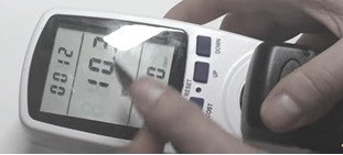
The time immediately started on the display, during which the power of the consumer, in this case the lamp, is measured. 0.4 watts is the power of the switched off lamp. We turn on the lamp, in operating mode it consumes 10.3 watts. We did not indicate the price per kilowatt, so there are zeros there.
Our lamp can change the power of light. As the lamp light increases, the power reading increases. When the second mode is turned on, the operating time is also shown at the top, in the second field kilowatt hours, since the device has not worked even one hour yet, zeros are shown. The bottom shows the number of days this consumer was measured.
In the next mode, the second field shows the voltage of the mains, the bottom shows the frequency of the current. The time is shown at the top of the display in all modes. When switching to the next mode, the current strength is shown in the center. At the bottom, a parameter of a certain factor is shown, about which there is no data yet, since the manufacturer of the device is Chinese.
The fifth mode shows the minimum power. In the sixth mode - maximum power.
It will be interesting to see the readings of these modes when the computer is running. For example, in sleep mode, with a normal open desktop, or when launching a powerful game.
In the following mode, set the cost of electricity with the setting buttons, to calculate the cost of energy consumption. So you can measure and calculate the consumption of any of your household appliances and devices, and you will know which devices you have are economical and which consume too much electricity.
Such a device has a low cost, about 14 dollars. This is a small price to pay to optimize your costs by calculating the power consumption of your devices.
Multifunctional digital wattmeter SM 3010

The device is used to measure voltage, frequency, power, direct and alternating current with one phase. And also, it is designed to control such devices with less accuracy.
The current measurement range is 0.002 - 10 amperes.
Voltage measurements:
Constant from 1 to 1000 volts.
Variable from 1 to 700 volts.
The frequency is measured in the range of 40-5000 hertz.
Measurement error
Current, voltage, DC power +
0,1%.
Current, voltage, AC power +
0.1% in the frequency range 40-1500 hertz.
Relative frequency measurement error in the range of 40-5000 hertz +
0,003%.
Dimensions of the body of the device 225 x 100 x 205 mm. Weight 1 kg. Power consumption less than 5 watts.
CPU measuring device 8506 – 120
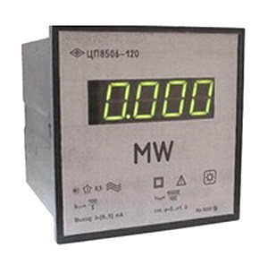
Serves to measure the power of an active and reactive 3-phase AC network, shows the current value of the power parameter on the indicator, converts it into an analog signal.
The measurements taken are shown in the form of numbers on the indicators in units of values that enter the device, or the input of the current or voltage transformer. In this case, the transformation coefficient is taken into account. The digital display is divided into four digits.
Purpose of the device - for measuring active and reactive power in 3-phase electric current networks with a frequency of 50 hertz.
Technical details
Power factor - 1.
Case dimensions 120 x 120 x 150 mm.
The height of the digits on the display is 20 mm.
The largest reading interval is 9999.
Degree of accuracy: 0.5.
Conversion time: less than 0.5 s.
Working temperature: from +5 to + 40 degrees.
Enclosure and panel protection class: IP 40.
Power consumption: 5 watts.
Weight less than 1.2 kg.
The presence of two coils in an electrodynamic device and the possibility of including them in two different circuits makes it possible to use these devices to measure the power of an electric current, i.e., as wattmeters.
From the expression for the angle of rotation of the moving system of the electrodynamic device (2.12), it follows that if the fixed coil is connected in series with the load z (Fig. 2-12), and the additional resistance Yad is connected in series with the moving coil so that this coil can be connected in parallel with the load , then the current in the moving coil is
![]()
where is the resistance of the coil; U - voltage on the load; - the constant of this device in terms of power; P is the power consumed by the load. Such a device is called a wattmeter. His scale is uniform.
For measuring electrical power in AC circuits, active and reactive power wattmeters are used.
Active power wattmeter. If an active additional resistance is included in the moving coil circuit so that the total resistance of this circuit R is equal to
then at voltage and in the network and at current i in the load
![]()
the current in the moving coil is
![]()

The instantaneous value of the torque in this case is equal to
![]()
and the average value of this moment for the period

Therefore, a wattmeter with an active additional resistance in the moving coil circuit measures the active power of the AC circuit.
The resulting conclusion has a simple physical explanation. Indeed, if an ammeter, voltmeter and wattmeter are included in the circuit with inductance (Fig. 2-13), then, since the moving system of the voltmeter turns under the action of only the applied voltage, regardless of the phase of this voltage (more precisely, under the influence of current in the coil proportional to the applied voltage), and the moving part of the ammeter turns under the action of only the current in the coil, regardless of the phase of this current. As for the movable part (coil) of the wattmeter, it turns only if the currents in both coils are not equal to zero, otherwise there will be no interaction. But in the circuit under consideration, the current of the moving coil is maximum when the current in circuit i is zero, and vice versa. The device will show nothing. This was to be expected, since the load either stores energy in the magnetic field, or returns it to the network.
From the graph of the currents of this circuit with inductance (Fig. 2-14) it follows that the currents coincide in direction (on the graph - on one side of the time axis) only during two (through one) quarters of the period for the period, and in the other two quarters period, the currents are in opposite directions. This means that the direction of the torque changes four times per period. Therefore, the moving system of the wattmeter during the period will experience the action of four impulses of the same value, but opposite in direction, and the device will not show anything, since the torque acting on the moving system is determined by its average value over the period.
If the shift angle between the currents is small (Fig. 2-15), then during the period the positive values of the torque greatly exceed the negative ones (in time and in values) and the moving system of the wattmeter will turn under the action of the average


values in response to the active power consumed by the given load.
So, the wattmeter shows the active power consumed from the network.
Reactive power wattmeter. In this wattmeter, in series with the moving coil, an inductive additional resistance is specially switched on (Fig. 2-16) such that
Let the applied voltage act in the circuit and the load creates a current
Then the instantaneous value of the torque is
![]()
![]()

After substitution and transformations, we get:
The average value of the torque for the period is
![]()
From this it follows that the wattmeter with inductive reactance in the moving coil circuit shows the reactive power of the AC circuit. This conclusion can be easily explained: in the case, for example, of purely inductive load, when energy is not irretrievably consumed from the network, such a circuit artificially shifts the phase of the current in the moving coil until it matches the phase of the current in the stationary one, so the wattmeter shows the value of reactive power.
So, an electrodynamic wattmeter has two coils: one is a current coil connected in series with the load, the other is a voltage coil connected in parallel with the load, the power consumption of which must be measured.
To turn on the device correctly (so that the arrow deviates in the right direction), one of the terminals of its winding is marked with an asterisk; these terminals of the wattmeter are called generator terminals. They should be connected to the load terminal that is connected to the generator (mains).
At present, it is necessary to measure the power and energy of direct current, active power and energy of alternating single-phase and three-phase current, reactive power and energy of three-phase alternating current, instantaneous value of power, as well as the amount of electricity in a very wide range.
Electric power is determined by the work done by the source of the electromagnetic field per unit time.
Active (absorbed by the electrical circuit) power
P a =UIcos >= I 2 R=U 2 /R,(1)
where U, I - effective values of voltage and current; - phase shift angle.
Reactive power
R R = U sin = I 2 X. (2)
Full power
P n = UI= PZ. These three types of power are related by the expression
P=(P a 2 +P 2 R ) (3)
So, power is measured within 1 W ... 10 GW (in DC and single-phase AC circuits) with an error of ± (0.01 ... 0.1)%, and with a microwave - with an error of ± (1 ... 5) %. Reactive power from units of var to Mvar is measured with an error of ±(0.1...0.5)%.
The measurement range of electrical energy is determined by the measurement ranges rated currents(1 nA...10 kA) and voltages (1 µV...1 MB), the measurement error is ±(0.1...2.5)%.
Reactive energy measurement is only of interest for industrial three-phase circuits.
Measurement of power in direct current circuits. In indirect power measurement, the ammeter and voltmeter method and the compensation method are used.
Ammeter and voltmeter method. In this case, the devices are switched on according to two schemes (Fig. 1).
The method is simple, reliable, economical, but has a number of significant drawbacks: the need to take readings on two
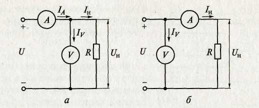
Rice. .one. Schemes for measuring power according to the readings of a voltmeter and an ammeter at small (a) and large (b) load resistance
appliances; the need to make calculations; low accuracy due to the summation of instrument errors.
Power R X , calculated from the instrument readings (Fig. 1a), has the form
It is greater than the actual value of the power consumed in the load R n, by the value of the power consumption of the voltmeter R v , i.e. P n = R X - R v .
The error in determining the power in the load is the smaller, the greater the input resistance of the voltmeter and the lower the load resistance.
Power R X , calculated according to instrument readings (Fig. 1., b) we have the form
It is greater than the actual value of the power consumption of the load by the value of the power consumption of the ammeter R BUT . The methodological error is the smaller, the lower the input resistance of the ammeter and the greater the load resistance.
compensation method. This method is used when a high accuracy of power measurement is required. With the help of a compensator, the load current and the voltage drop across the load are alternately measured. The measured power is determined by the formula
P= U n I n . (4)
With direct measurement, active power is measured by electromechanical (electrodynamic and ferrodynamic systems), digital and electronic wattmeters.
Electrodynamic wattmeters are used as portable devices for accurate power measurements (class 0.1 ... 2.5) in DC and AC circuits with a frequency of up to several thousand hertz.
Ferrodynamic shield voltmeters are used in alternating current circuits of industrial frequency (class 1.5 ... 2.5).

In a wide frequency range, digital wattmeters are used, the basis
make up various power converters (for example, thermoelectric), UPT, microprocessor and DOC. Digital wattmeters carry out automatic selection of measurement limits, self-calibration and an external interface is provided.
To measure power in high-frequency circuits, special and electronic wattmeters are also used.
To measure reactive power at low frequencies, reactive wattmeters (varmeters) are used, in which, by using special circuits, the deviation of the moving part of the electrodynamic IM is proportional to reactive power.
The inclusion of electromechanical wattmeters directly into the electrical circuit is permissible at load currents not exceeding 10 ... 20 A and voltages up to 600 V. Power measurement at high load currents and in high voltage circuits is carried out by a wattmeter with measuring current transformers TA and stress TV(fig..2).
Measurement of active power in three-phase current circuits. One wattmeter method. This method is used only in a symmetrical system with a uniform phase load, the same phase angles between the vectors I and U and with full symmetry of stresses (Fig..3).
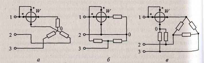
Fig..3. Schemes for connecting a wattmeter to a three-phase three-wire circuit with full symmetry of the load connection:
a- a star; b - triangle; in ~- with artificial zero point

Fig.4. Schemes for including two wattmeters in a three-phase circuit: a- in the 1st and 3rd; b- in the 1st and 2nd; in- in the 2nd and 3rd
On fig. .3, a the load is star connected and the zero point is available. In Fig.3, b the load is delta connected, the wattmeter is in phase. On fig. .3, in the load is delta connected with an artificial zero point. An artificial zero point is created using two resistors, each of which is equal to the resistance of the wattmeter voltage winding circuit (usually indicated in technical passport on a wattmeter).
The wattmeter readings will correspond to the power of one phase, and the power of the entire three-phase network in all three cases of switching on the device will be equal to the power of one phase multiplied by three:
P =3 P w
Method of two wattmeters. This method is used in a three-phase three-wire circuit, regardless of the connection scheme and the nature of the load, both with symmetry and asymmetry of currents and voltages. Asymmetry is a system in which the powers of individual phases are different. The current windings of wattmeters are connected to any two phases, and the voltage windings are connected to linear voltages (Fig. 4).
Apparent power can be expressed as the sum of the readings of two wattmeters. So, for the circuit shown in Fig..4, a,
where 1 - phase angle between current I 1 and line voltage U 12, 2 - phase angle between current I 3 and line voltage U 32 . In a particular case, with a symmetrical voltage system and the same phase load 1 , = 30° - and 2 = 30° - wattmeter readings will be:
With an active load (= 0), the readings of the wattmeters will be the same, since P W ] = P W 2 IUcos30°.
With a load with a shear angle cp = 60°, the readings of the second wattmeter are equal to zero, since P W 2 = IU cos(30° + ) = IU cos(30° + 60°) = 0, in which case the power of the three-phase circuit is measured with one wattmeter.
With a load with a shear angle > 60°, the power measured by the second wattmeter will be negative, since (30° +) is greater than 90°. In this case, the moving part of the wattmeters will turn in the opposite direction. To read, it is necessary to change the phase of the current in one of the wattmeter circuits by 180 °. In this case, the power of the three-phase current circuit is equal to the difference in the readings of the wattmeters
Three wattmeter method. To measure the power of a three-phase circuit with an unbalanced load, three wattmeters are turned on, and the total power in the presence of a neutral wire will be equal to the arithmetic sum of the readings of three wattmeters. In this case, each wattmeter measures the power of one phase, the readings of the wattmeter, regardless of the nature of the load, will be positive (the parallel winding is connected to the phase voltage, that is, between the linear wire and zero). If the zero point is not available and there is no neutral wire, then parallel circuits of devices can form an artificial zero point, provided that the resistances of these circuits are equal to each other.
Measurement of reactive power in single-phase and three-phase circuits. Although reactive power determines neither the work done nor the energy transferred per unit of time, its measurement is also important. The presence of reactive power leads to additional losses of electrical energy in transmission lines, transformers and generators. Reactive power is measured in reactive volt-amperes (var) in both single-phase and three-phase three- and four-wire AC circuits with electrodynamic and ferrodynamic wattmeters or specially designed for measuring reactive power. The difference between a reactive wattmeter and a conventional one is that it has a complicated parallel circuit circuit to obtain a phase shift of 90 °
between the current and voltage vectors of this circuit. Then the deviation of the moving part will be proportional to the reactive power R R = U sin . Reactive wattmeters are mainly used for laboratory measurements and calibration of reactive meters.
Reactive power in a three-phase symmetrical circuit can also be measured with an active wattmeter: for this, the current coil is connected in series to phase A, the voltage coil between phases B and C.
Power measurement in high frequency circuits. For this purpose, both direct and indirect measurements can be used, and in some cases indirect measurements may be preferable, since it is sometimes easier to measure the current and voltage at the load than directly the power. Direct measurement of power in high and high frequency circuits is carried out by thermoelectric, electronic, Hall-effect wattmeters and digital wattmeters.
Indirect measurements are carried out by the oscillographic method. It is used mainly when the circuit is powered by a non-sinusoidal voltage, at high frequencies, low-power voltage sources, etc.
Measurement of energy in single-phase and three-phase circuits. Energy is measured by electromechanical and electronic electricity meters. Electronic electricity meters have better metrological characteristics, greater reliability and are promising means of measuring electrical energy.
4. Phase and frequency measurement
Phase characterizes the state of a harmonic signal at a certain point in time t. The phase angle at the initial moment of time (time reference), i.e. at t = 0, called zerovym (initial) phase shift. The phase difference is usually measured between current and voltage or between two voltages. In the first case, they are more often interested not in the phase angle itself, but in the value of cos or power factor. Cos is the cosine of the angle by which the load current leads or lags behind the voltage applied to this load. phase shift of two harmonic signals of the same frequency is called the modulus of the difference of their initial phases = | 1 - 2 |. The phase shift does not depend on time if the initial phases 1 and 2 remain unchanged. The phase difference is expressed in radians or degrees.
Methods for measuring the phase shift angle. These methods depend on the frequency range, level and shape of the signal, the required accuracy and the availability of measuring instruments. There are indirect and direct changes in the phase angle.
indirect measurement. Such a measurement of the phase angle between the voltage U and current I in the load in single-phase circuits
carried out using three instruments - a voltmeter, an ammeter and a wattmeter (Fig. 5). The angle is determined by calculation from the found value cos:
![]()
The method is usually used at an industrial frequency and provides low accuracy due to the methodological error caused by the own consumption of devices; it is quite simple, reliable, and economical.
In three-phase symmetrical circuit the value of cos can be determined by the following measurements:
power, current and voltage of one phase;
measurement of active power by the method of two wattmeters;
measurement of reactive power by the method of two wattmeters with an artificial neutral point.
Among the oscillographic methods for measuring the phase, the methods of linear sweep and ellipse are most widely used. The oscillographic method, which makes it possible to observe and fix the signal under study at any time, is used in a wide frequency range in low-power circuits for rough measurements (5 ... 10%). The linear sweep method involves the use of a two-beam oscilloscope, on the horizontal plates of which a linear sweeping voltage is applied, and on the vertical plates - a voltage, between which the phase shift is measured. For sinusoidal curves on the screen, we get an image of two voltages (Fig. 6, a) and according to the measured segments AB and AC, the angle of shift between them is calculated
where AB is the segment between the corresponding points of the curves when they pass through zero along the axis X; AC - segment corresponding to the period.
Measurement error X depends on the reading error and the phase error of the oscilloscope.

If, instead of a linear sweep, a sinusoidal sweep voltage is used, then the Lissajous figures obtained on the screen at equal frequencies give an ellipse shape on the oscilloscope screen (Fig. 6b). Shear angle x =arcsin(AB/VG).
This method allows you to measure x within 0 90 o without determining the sign of the phase angle.
The measurement error x is also determined by the reading error

Fig..6. Curves obtained on the screen of a two-beam oscilloscope: with a linear (a) and sinusoidal (b) sweep
and differences in the phase shifts of the channels X and Y oscilloscope.
The use of an AC compensator with a calibrated phase shifter and an electronic oscilloscope as an indicator of phase equality allows a fairly accurate measurement of the phase angle. The measurement error in this case is determined mainly by the error of the phase shifter used.
Direct measurement. Direct measurement of the phase shift angle is carried out using electrodynamic, ferrodynamic, electromagnetic, electronic and digital phase meters. The most commonly used electromechanical phase meters are electrodynamic and electromagnetic ratiometric phase meters. The scale of these instruments is linear. Used in the frequency range from 50 Hz to 6 ... 8 kHz. Accuracy classes - 0.2; 0.5. They are characterized by a large power consumption 1 (5 ... 10 W).
In a three-phase symmetrical circuit, the measurement of the phase shift angle or cos is carried out by single-phase or three-phase phase meters.
Digital phase meters are used in low-power circuits in the frequency range from units of Hz to 150 MHz, accuracy classes - 0.005; 0.01; 0.02; 0.05; 0.1; 0.5; 1.0. In electronically counting digital phase meters, the phase shift between two voltages is converted into a time interval filled with pulses of a stable frequency with a certain period, which are counted by an electronic pulse counter. The components of the errors of these devices are: discretization error, error of the stable frequency generator, error depending on the accuracy of the formation and transmission of the time interval.
Frequency measurement methods. Frequency is one of the most important characteristics of a batch process. It is determined by the number of complete cycles (periods) of signal change per unit of time. The range of frequencies used in technology is very large and ranges from fractions of a hertz to tens. The entire frequency spectrum is divided into two ranges - low and high.
Low frequencies: infrasonic - below 20 Hz; sound - 20...20000 Hz; ultrasonic - 20...200 kHz.
High frequencies: high - from 200 kHz to 30 MHz; ultra-high - 30...300 MHz.
Therefore, the choice of frequency measurement method depends on the range of measured frequencies, the required measurement accuracy, the magnitude and shape of the voltage of the measured frequency, the power of the measured signal, the availability of measuring instruments, etc.
Direct measurement. The method is based on the use of electromechanical, electronic and digital frequency meters.
Electromechanical frequency meters use the measuring mechanism of electromagnetic, electrodynamic and ferrodynamic systems with a direct reading of the frequency on the scale of a ratiometric meter. They are easy to design and operate, reliable, and have a fairly high accuracy. They are used in the frequency range from 20 to 2500 Hz. Accuracy classes - 0.2; 0.5; 1.0; 1.5; 2.5.
Electronic frequency meters are used for measurements in the frequency range from 10 Hz to several megahertz, with input signal levels of 0.5 ... 200 V. They have a large input impedance, which ensures low power consumption. Accuracy classes - 0.5; 1.0 and below.
Digital frequency counters are used for very precise measurements in the range of 0.01 Hz...17 GHz. Sources of error are the error from the discreteness and instability of the quartz oscillator.
Bridge method. This method of frequency measurement is based on the use of frequency-dependent AC bridges supplied with the voltage of the measured frequency. The most common bridge circuit for measuring frequency is the capacitive bridge. The bridge frequency measurement method is used to measure low frequencies within 20 Hz ... 20 kHz, the measurement error is 0.5 ... 1%.
indirect measurement. The method is carried out using oscilloscopes: by interference patterns (Lissajous figures) and a circular sweep. The methods are simple, convenient and quite accurate. They are used in a wide frequency range of 10 Hz ... 20 MHz. The disadvantage of the Lissajous method is the difficulty in deciphering the figures when the ratio of the figures is more than 10 and, therefore, the measurement error increases due to the establishment of the true frequency ratio. With the circular sweep method, the measurement error is mainly determined by the quantization error of the fundamental frequency.
METHODS AND TOOLS FOR MEASURING THE PARAMETERS OF MEASURING CIRCUITS
We advise you to read
, diagnosis, treatment Treatment of urogenital chlamydia") Chlamydia urogenital - description, causes, symptoms (signs), diagnosis, treatment Treatment of urogenital chlamydia
Chlamydia urogenital - description, causes, symptoms (signs), diagnosis, treatment Treatment of urogenital chlamydia The benefits and significance of hydroamino acid threonine for the human body L threonine what
 To wait or not to wait for a guy from the army For what reason can they be commissioned from the army
 Baked apples with cottage cheese Baked apples with cottage cheese

