The principle of operation of the electric motor.
electric motor – it's just a device for efficient conversion electrical energy into mechanical.
This transformation is based on magnetism. Electric motors use permanent magnets and electromagnets, and use the magnetic properties of various materials to create these amazing devices.
There are several types of electric motors. We note two main classes: AC and DC.
AC (Alternating Current) motors require a power source to operate. alternating current or voltage (you can find such a source in any electrical outlet in the house).
Electric motors of class DC (Direct Current) require a source of direct current or voltage for operation (you can find such a source in any battery).
Universal motors can be operated from any type of source.
Not only the design of the motors is different, the way to control the speed and torque is different, although the principle of energy conversion is the same for all types.
The device and principle of operation of the simplest electric motor.
The design of an electric motor is based on an effect discovered by Michael Faraday in 1821: that the interaction of an electric current and a magnet can cause continuous rotation. One of the first engines that found practical application was the engine of Boris Semenovich Jacobi (1801–1874), which set in motion a boat with 12 passengers on board. However, for the widespread use of the electric motor, a source of cheap electricity was needed - an electromagnetic generator.
The principle of operation of an electric motor is very simple: rotation is caused by magnetic attraction and repulsion forces acting between the poles of a movable electromagnet (rotor) and the corresponding poles of an external magnetic field created by a fixed electromagnet (or permanent magnet) - the stator.
The rotating part of the electric machine is called the rotor (or armature), and the stationary part is called the stator. In a simple DC motor, the coil unit serves as the rotor and the permanent magnet serves as the stator.
The difficulty lies in achieving continuous rotation of the engine. And for this, it is necessary to make sure that the pole of the movable electromagnet, attracted to the opposite pole of the stator, automatically changes to the opposite - then the rotor will not freeze in place, but will turn further - by inertia and under the action of the repulsion that has arisen at that moment.
A collector is used for automatic switching of the rotor poles. It is a pair of plates fixed on the rotor shaft, to which the rotor windings are connected. Current is supplied to these plates through current-collecting contacts (brushes). When the rotor is rotated 180°, the plates change places - this automatically changes the direction of the current and, consequently, the poles of the movable electromagnet. Since like poles repel each other, the coil continues to rotate, and its poles are attracted to the corresponding poles on the other side of the magnet.
The simplest electric motor
The simplest electric motor runs only on DC(from battery). The current passes through a loop located between the poles of a permanent magnet. The interaction of the magnetic fields of the frame with current and the magnet causes the frame to rotate. After each half-turn, the collector switches the contacts of the frame, suitable for the battery, and therefore the frame rotates.
In some motors, an electromagnet is used instead of a permanent magnet to create a magnetic field. The coils of wire of such an electromagnet are called the excitation winding.
Electric motors are used everywhere. Even at home, you can find a huge number of electric motors. Electric motors are used in the clock, in the fan microwave oven, in washing machine, in computer fans, in an air conditioner, in a juicer, etc., etc. Well, the electric motors used in industry can be listed endlessly. Physical sizes range from the size of a match head to the size of a locomotive engine.
The industrial electric motor shown below operates on both direct and alternating current. Its stator is an electromagnet that creates a magnetic field. The motor windings are connected in turn through the brushes to the power source. One by one, they turn the rotor through a small angle, and the rotor rotates continuously.

Electrical measuring instruments.
Electrical measuring instruments -a class of devices used to measure various electrical quantities.
The group of electromagnetic devices is the most common. The principle of their operation, first used by F. Kohlrausch in 1884, is based on the movement of a movable iron part under the influence of a magnetic flux created by a coil through which a current is passed. The practical implementation of this principle is varied.
The orienting action of the magnetic field on the circuit with current is used in electrical measuring instruments of the magnetoelectric system - ammeters, voltmeters, etc.
The device of the device of the magnetoelectric system
The measuring device of the magnetoelectric system is arranged as follows.
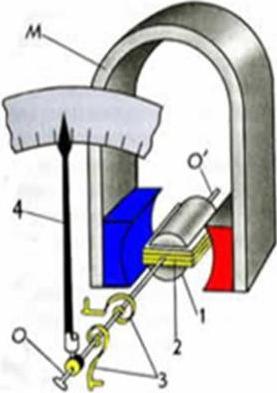
They take a light aluminum frame 2 of a rectangular shape, wind a coil of thin wire around it. The frame is mounted on two semi-axes O and O ", to which the arrow of the device 4 is also attached. The axis is held by two thin spiral springs 3. The elastic forces of the springs, returning the frame to the equilibrium position in the absence of current, are selected such that they are proportional to the angle of deviation of the arrow from the position balance.The coil is placed between the poles of a permanent magnet M with tips of the shape of a hollow cylinder.Inside the coil is a soft iron cylinder 1.This design provides a radial direction of the lines of magnetic induction in the area where the turns of the coil are located (see figure).

As a result, at any position of the coil, the forces acting on it from the side of the magnetic field are maximum and, at a constant current strength, are constant. The vectors F and -F represent the forces acting on the coil from the magnetic field and turning it. The coil with current rotates until the elastic forces from the side of the spring balance the forces acting on the frame from the side of the magnetic field. By increasing the current strength in the frame by 2 times, the frame will rotate through an angle twice as large. This is because F m ~I.
The forces acting on the frame with current are directly proportional to the current strength, that is, by calibrating the device, you can measure the current strength in the frame.
In the same way, you can set the device to measure the voltage in the circuit, if you calibrate the scale in volts, and the resistance of the loop with current must be chosen very large compared to the resistance of the circuit section on which we measure the voltage.
The operation of the electric motor and internal combustion engine
Internal combustion engine
Today we cannot do without cars. However, they are all different appearance, size and power but the principle of operation of the engine is basically the same. Today we will talk about the operation of the engine. After all, probably, many were interested in the principle of its work. An engine is a complex mechanism, but we will understand its main, main elements.
There are two main types of engines: two-stroke and four-stroke. In two-stroke engines, all work cycles (processes of fuel mixture intake, exhaust gas exhaust, purge) occur during one revolution of the crankshaft in two main cycles. Engines of this type do not have valves (as in four-stroke internal combustion engines), their role is played by a piston, which, when moving, closes the inlet, outlet and purge windows. Therefore, they are simpler in design.
The power of a two-stroke engine with the same cylinder size and shaft speed is theoretically twice that of a four-stroke engine due to a larger number of operating cycles. However, the incomplete use of the piston stroke for expansion, the worst release of the cylinder from residual gases and the expenditure of a part of the generated power for blowing lead to an increase in power by only 60–70%.
So, consider the design of a two-stroke internal combustion engine, shown in Figure 1:
The engine consists of a crankcase, in which a crankshaft and a cylinder are mounted on bearings on both sides. A piston moves inside the cylinder - a metal cup surrounded by spring rings (piston rings) embedded in grooves on the piston. Piston rings do not allow the gases generated during the combustion of fuel to pass between the piston and the cylinder walls. The piston is equipped with a metal rod - a pin, it connects the piston to the connecting rod. The connecting rod transfers the linear reciprocating motion of the piston into the rotational motion of the crankshaft. Further, in particular on a scooter, the rotational movement is transmitted to the variator.
Lubrication of all friction surfaces and bearings inside two-stroke engines occurs with the help of a fuel mixture, in which the required amount of oil is mixed. Figure 1 shows that the fuel mixture (yellow) enters both the crank chamber of the engine (this is the cavity where the crankshaft is fixed and rotates) and the cylinder. There is no lubrication anywhere, and if there was, it was washed off with the fuel mixture. For this reason, oil is added in a certain proportion to gasoline. The type of oil used is special, specifically for two-stroke engines. It must withstand high temperatures and, when burned with fuel, leave a minimum of ash deposits. Now about the principle of work. The entire working cycle in the engine is carried out in two cycles.
1. Compression stroke. The piston moves from the bottom dead center of the piston (in this position the piston is in Fig. 2, hereinafter referred to as BDC for short) to the top dead center of the piston (piston position in Fig. 3, hereinafter TDC), first blocking the purge 2, and then the outlet 3 windows. After the piston closes the outlet window in the cylinder, the compression of the combustible mixture that has previously entered it begins. At the same time, in the crank chamber 1, due to its tightness and after the piston closes the purge windows 2, a vacuum is created under the piston, under the action of which a combustible mixture enters the crank chamber from the carburetor through the inlet window and the opening valve.
2. Stroke stroke. When the piston is near TDC, the compressed working mixture (1 in Fig. 3) is ignited by an electric spark from a candle, as a result of which the temperature and pressure of the gases increase sharply. Under the action of thermal expansion of gases, the piston moves to the NDC, while the expanding gases perform useful work. At the same time, going down, the piston creates high pressure in the crank chamber (compressing the air-fuel mixture in it). Under pressure, the valve closes, thus preventing the combustible mixture from re-entering the intake manifold and then into the carburetor.
When the piston reaches the outlet window (1 in Fig. 4), it opens and the exhaust gases are released into the atmosphere, the pressure in the cylinder decreases. With further movement, the piston opens the purge window (1 in Fig. 5) and the combustible mixture compressed in the crank chamber enters through the channel (2 in Fig. 5), filling the cylinder and purging it from exhaust gas residues.
It is worth mentioning the principle of ignition. Since the fuel mixture needs time to ignite, a spark appears on the candle a little before the piston reaches TDC. Ideally, the faster the piston moves, the earlier the ignition should be, because the piston from the moment of the spark reaches TDC faster. There are mechanical and electronic devices that change the ignition angle depending on the engine speed. Practically for scooters up to 2000 onwards. there were no such systems and the ignition timing was set based on optimal speed. On some scooters, such as the Honda Dio ZX AF35, an electronic switch with dynamic advance is installed. With it, the engine develops more power.
Advantages of four-stroke engines
* Greater resource.
* Great economy.
* Cleaner exhaust.
* No complex exhaust system required.
* Less noise. * No need to pre-mix oil with gasoline
Advantages of two-stroke engines
* Lack of bulky lubrication and gas distribution systems for gasoline options.
* High power in terms of 1 liter of working volume.
*Easier and cheaper to manufacture
electric motor
History of creation
In 1821, investigating the interaction of conductors with current and magnets, Faraday found that an electric current passing through a conductor can cause this conductor to rotate around a magnet or cause a magnet to rotate around a conductor. This experience proved the fundamental possibility of building an electric motor.
The possibility of converting electrical energy into mechanical energy has been shown in many other experiments. So, in P. Barlow's book "The Study of Magnetic Attractions", published in 1824, a device known as "Barlow's wheels" was described.
Barlow's wheel, according to the principle of operation, was a unipolar electric machine operating in a motor mode: as a result of the interaction of the magnetic field of permanent magnets and the current passing through both copper gears sitting on the same axis, the wheels begin to rotate rapidly in the same direction. Barlow found that a change in contacts or a change in the position of the poles of the magnets immediately causes a change in the direction of rotation of the wheels.
As an example of another design of an electric motor, the device described in 1833 by the English scientist W. Ricci can serve. The magnetic field in this engine was created by a permanent stationary horseshoe magnet. An electromagnet was placed between these poles on a vertical axis, through the winding of which a current was passed. The direction of the current was periodically changed by the switch. The interaction of the poles of the permanent magnet and the electromagnet led to the rotation of the electromagnet around the axis. However, this electric motor, due to its primitive design and low power, could not be of practical importance.
In the device of the American physicist J. Henry, the change in the polarity of the electromagnet occurred due to a change in the direction of the current flowing through its winding. It brought the electromagnet into a uniform rocking motion. In the model built by Henry himself, the electromagnet made 75 swings per minute. The power of engines of this type was very small, about 0.05 watts.
In 1834-1860. constructions appeared with the rotational movement of a clearly pole anchor. The torque on the shaft of such engines was usually sharply pulsating.
Most important works for the design of electric motors belong to the Russian scientist B. S. Yakobi. Studying the designs of the electric motors of his predecessors, in which the reciprocating or rocking motion of the armature was carried out, Jacobi commented on one of them: “such an apparatus will be no more than a fun toy for enriching physical cabinets” and that “it will not be possible to apply it on a large scale with some economic benefit. Therefore, he turned his attention to building a more powerful electric motor with a rotary movement of the armature.
In 1834, Jacobi built and described an electric motor that operated on the principle of attraction and repulsion between electromagnets. This engine had two groups of U-shaped electromagnets, one of which was located on a fixed frame, and the other similar group - on a rotating disk. A battery of galvanic cells was used as a current source for powering the electromagnets. A commutator was used to alternately change the polarity of the movable electromagnets.
Jacobi built his first electric motor in May 1834, and in November of the same year he presented a report on this device to the Paris Academy of Sciences. It was read at a meeting of the Academy in December 1834 and immediately published.
In 1837, the American technician T. Davenport also built an electric motor with direct rotation of the armature, where movable electromagnets interacted with fixed permanent magnets.
Principle of operation
DC motors are used in those electric drives that require a large range of speed control, high accuracy in maintaining the speed of rotation of the drive, speed control up from the nominal.
How are DC motors
The operation of a DC electric motor is based on the phenomenon of electromagnetic induction. From the basics of electrical engineering, it is known that a current-carrying conductor placed in a magnetic field is subjected to a force determined by the left hand rule:
where I is the current flowing through the conductor, B is the induction of the magnetic field; L is the length of the conductor.
When the conductor crosses the magnetic lines of force cars in it are induced electromotive force, which, in relation to the current in the conductor, is directed against it, therefore it is called reverse or counteracting (counter-e.d. s). Electric power in the engine is converted into mechanical energy and is partially spent on heating the conductor.
Structurally, all DC electric motors consist of an inductor and an armature separated by an air gap.
The DC motor inductor is used to create a stationary magnetic field of the machine and consists of a frame, main and additional poles. The frame is used to fix the main and additional poles and is an element of the magnetic circuit of the machine. On the main poles there are excitation windings designed to create a magnetic field of the machine, on the additional poles there is a special winding that serves to improve switching conditions.
The armature of a DC motor consists of a magnetic system assembled from separate sheets, a working winding laid in grooves, and a collector used to supply working winding direct current.
The collector is a cylinder mounted on the motor shaft and selected from copper plates isolated from each other. There are protrusions-cockerels on the collector, to which the ends of the armature winding sections are soldered. Removal of current from the collector is carried out using brushes that provide sliding contact with the collector. The brushes are fixed in brush holders, which hold them in a certain position and provide the necessary pressing of the brush on the surface of the collector. Brushes and brush holders are fixed on a traverse connected to the motor housing.
Switching in DC motors
During the operation of the DC motor, the brushes, sliding over the surface of the rotating collector, sequentially move from one collector plate to another. In this case, the parallel sections of the armature winding are switched and the current in them changes. The change in current occurs at a time when the coil of the winding is short-circuited by the brush. This switching process and the phenomena associated with it are called switching.
At the moment of switching in the short-circuited section of the winding, e is induced under the influence of its own magnetic field. d.s. self-induction. The resulting e. d.s. causes an additional current in the short-circuited section, which creates an uneven distribution of current density on the contact surface of the brushes. This circumstance is considered the main cause of the sparking of the collector under the brush. The quality of switching is evaluated by the degree of sparking under the running edge of the brush and is determined by the scale of the degrees of sparking.
Ways to excite DC motors
The excitation of electrical machines is understood as the creation of a magnetic field in them, which is necessary for the operation of an electric motor.
According to the method of excitation, DC electric motors are divided into four groups:
1. C independent arousal, in which the excitation winding NOV is powered by an external DC source.
2. C parallel excitation(shunt), in which the excitation winding SHOV is connected in parallel with the power source of the armature winding.
3. With serial excitation (series), in which the excitation winding of the SOW is connected in series with the armature winding.
4. Engines with mixed excitation (compound), which have a series SOV and a parallel SOV of the excitation winding.
Starting DC motors
At the initial moment of starting the engine, the anchor is stationary and counter-e. d.s. and the armature voltage is zero, therefore Ip = U / Rya.
The resistance of the armature circuit is small, so the starting current is 10 to 20 times or more than the rated current. This can cause significant electrodynamic forces in the armature winding and its excessive overheating, so the engine is started using starting rheostats - active resistances included in the armature circuit.
Motors up to 1 kW allow direct starting.
The resistance value of the starting rheostat is selected according to the permissible starting current of the motor. The rheostat is stepped to improve the smoothness of starting the electric motor.
At the beginning of the start, the entire resistance of the rheostat is introduced. As the armature speed increases, counter-e occurs. d.s., which limits the starting currents. Gradually removing step by step the resistance of the rheostat from the armature circuit, the voltage supplied to the armature is increased. The speed of a DC motor can be controlled in three ways: by changing the motor excitation flux, by changing the voltage applied to the motor, and by changing the resistance in the armature circuit.
Most wide application received the first two methods of regulation, the third method is rarely used: it is uneconomical, while the motor speed significantly depends on load fluctuations. Mechanical characteristics of a DC electric motor with various methods of speed control
The bold line is the natural dependence of the speed on the torque on the shaft, or, which is the same, on the armature current. The straight line of the natural mechanical characteristic deviates somewhat from the horizontal dashed line. This deviation is called instability, non-rigidity, sometimes static. The group of non-parallel lines I corresponds to the regulation of the speed by excitation, parallel lines II are obtained as a result of changing the armature voltage, and finally, fan III is the result of introducing an active resistance armature into the circuit.
The value of the excitation current of a DC motor can be controlled using a rheostat or any device whose active resistance can be changed in value, such as a transistor. With an increase in resistance in the circuit, the excitation current decreases, the engine speed increases. When the magnetic flux is weakened mechanical characteristics are located above the natural (i.e., above the characteristics in the absence of a rheostat). Increasing the engine speed causes increased sparking under the brushes. In addition, when the electric motor is operated with a weakened flow, the stability of its operation decreases, especially when variable loads on the shaft. Therefore, the limits of speed control in this way do not exceed 1.25 - 1.3 of the nominal.
Variable voltage control requires a constant current source such as a generator or converter. Such regulation is used in all industrial electric drive systems: a generator - a DC motor (G - DPT), an electric machine amplifier - a DC motor (EMU - DPT), a magnetic amplifier - a DC motor (MU - DPT), a thyristor converter - a DC motor (T - DPT).
Braking of DC motors
In electric drives with DC motors, three methods of braking are used: dynamic, regenerative and reverse current braking.
Dynamic braking DC motor is carried out by short-circuiting the armature winding of the motor or through a resistor. In this case, the DC motor begins to work as a generator, converting the mechanical energy stored by it into electrical energy. This energy is released in the form of heat in the resistance to which the armature winding is closed. Dynamic braking provides an exact stop of the electric motor.
Regenerative braking of a DC motor is carried out when the electric motor connected to the network is rotated by the actuator at a speed exceeding the ideal idle speed. Then e. d.s. induced in the motor winding exceeds the value of the mains voltage, the current in the motor winding changes direction to the opposite. The electric motor switches to work in the generator mode, giving energy to the network. At the same time, a braking torque occurs on its shaft. Such a mode can be obtained in the drives of lifting mechanisms when lowering the load, as well as when controlling the speed of the engine and during braking processes in DC electric drives.
Regenerative braking of a DC motor is the most economical way, as it returns the electricity to the grid. In the electric drive of metal-cutting machine tools, this method is used for speed control in the G-DPT and EMU-DPT systems.
Braking by counter-inclusion of a DC motor is carried out by changing the polarity of the voltage and current in the armature winding. When the armature current interacts with the magnetic field of the field winding, a braking torque is created, which decreases as the motor speed decreases. When the motor speed decreases to zero, the motor must be disconnected from the network, otherwise it will start to turn in the opposite direction.
History of the electric motor
The principle of converting electrical energy into mechanical energy by an electromagnetic field was demonstrated by the British scientist Michael in 1821 and consisted of a free-hanging wire dipped in mercury. A permanent magnet was installed in the middle of the mercury bath. When current was passed through the wire, the wire rotated around the magnet, showing that the current caused a cyclic magnetic field around the wire. This engine is often demonstrated in school physics classes using brine instead of toxic mercury. This is the simplest form of the class of electric motors. The next improvement is . It was a demonstration device, unusable in practical applications due to limited power.
The inventors sought to create an electric motor for industrial needs. They tried to make the iron core move in the field of an electromagnet reciprocating, that is, the way a piston moves in a steam engine cylinder. The Russian scientist B.S. Yakobi took a different path. In 1834, he created the world's first practical electric motor with a rotating armature and published a theoretical work "On the use of electromagnetism to drive a machine." wrote that his engine is simple and "gives a direct circular motion, which is much easier to convert into other types of motion than reciprocating."
rotational movement armature in the Jacobi engine was due to the alternating attraction and repulsion of electromagnets. Fixed group of U-shaped electromagnetswas powered by current directly from a galvanic battery, and the direction of the current in these electromagnets remained unchanged. The movable group of electromagnets was connected to the battery through a commutator, with the help of which the direction of the current in each electromagnet changed once per revolution of the disk. In this case, the polarity of the electromagnets changed accordingly, and each of the movable electromagnets was alternately attracted and repelled by the corresponding stationary electromagnet: the motor shaft began to rotate. The power of such an engine was only 15 watts. Subsequently, Jacobi brought the power of the electric motor to 550 watts. This engine was installed first on a boat and later on a railway platform.
In 1839, Jacobi built a boat with an electromagnetic engine, which developed 1 horsepower from 69 Grove elements and moved the boat with 14 passengers along the Neva against the current. This was the first application of electromagnetism to locomotion on a large scale.
The structure of the electric motor
Rotor -. stator.
Stator -fixed partelectrical, scapularrotor. In my case, the battery plays the role of the stator. The stator has two poles.
Application of electric motor
Electric motors are used everywhere. Even at home, you can find a huge number of electric motors. Electric motors are used in clocks, microwave oven fans, washing machines, computer fans, air conditioners, juicers, etc.
The principle of operation of the electric motor
An electric motor is simply a device for efficiently converting electrical energy into mechanical energy.
This transformation is based on magnetism. Electric motors use permanent magnets and electromagnets, and use the magnetic properties of various materials to create these amazing devices.
Rotor -a rotating part of engines and working machines, on which organs are located that receive energy from the working fluid or give it to the working fluid. The rotor is made in the form of drums, disks, wheels (in my case, a ring). The rotor is closely related to the conceptstator. the rotor has at least one pair of poles (like the stator, otherwise the motor cannot run)
Stator -fixed partelectrical, scapularand another machine interacting with the moving part -rotor. In my case, the battery plays the role of the stator). The stator has two poles.
Research work on the topic: "Electric motor" The work was carried out by: a student of the 9th grade of the Municipal Educational Institution "Gymnasium No. 1 in Maysky" Golovchansky Sergey Supervisor: teacher of physics of the Municipal Educational Institution "Gymnasium No. 1 in Maisky" Zhuravlev Alexander Mikhailovich
Object of study: electric motor. Subject of study: the level of its use in modern society thanks to its technical characteristics. Purpose: to independently produce models of electric motors, which are the starting point for the creation of modern electric motors, and experimentally determine the efficiency of a model of a training electric motor. Tasks: - to study the principles of operation of an electric motor; - to get acquainted with the history of the development of an electric motor; ; - make models of electric motors; - calculate the efficiency of the electric motor.
HISTORICAL PATH OF THE ELECTRIC MOTOR Jacobi B.S. 1834 created the world's first practical electric motor with a rotating armature Michael Faraday 1821 demonstrated the principle of converting electrical energy into mechanical energy by an electromagnetic field Peter Barlow 1824 Barlow's wheel had no practical significance and has remained to this day a laboratory demonstration instrument
The Physics of an Electric Motor The Left Hand Rule A magnetic field is a form of matter that surrounds moving electric charges. The term "magnetic field" was first introduced in 1845 by the English physicist Faraday. The force with which a magnetic field acts on a current-carrying conductor is called the ampere force. The direction of the Ampère force vector is determined by the left hand rule.
OPERATING PRINCIPLE OF AN ELECTRIC MOTOR In electric motors, the action of the Ampere force is used to convert electrical energy into mechanical energy. The efficiency of powerful electric motors reaches 98%. No other engine has such a high efficiency.
Electric motor conversion efficiency
The main conclusions of the work 1. N. Syadristy made the smallest electric motor in the world. The engine has 15 parts, but its dimensions are 4 times smaller than a poppy seed! 2. The largest DC electric motors are used to drive the propellers of the Russian nuclear-powered icebreakers Sibir and Arktika. Engine power 176,000 kW, efficiency - 0.95. 3. Trying to make this or that device on my own, I found that each of them has its own “secrets”, without knowing which the devices simply will not work. 4. Having done a lot of work on studying the literature on the creation of the first electric motors, on the physical principles of their operation, on their implementation today in all branches of life, I can say with confidence that the electric motor is indeed a modern alternative invention.
Plan:
- Introduction
- 1 Operating principle
- 2
Classification of electric motors
- 2.1 DC motors
- 2.2 AC motors
- 2.3
- 3 History Notes
Introduction
Electric motors of different power (750 W, 25 W, for a CD player, for a toy, for a floppy drive). Battery "Krona" is given for comparison
Electrical engine- an electrical machine (electromechanical converter), in which electrical energy is converted into mechanical energy, side effect is the release of heat.
1. Operating principle
The operation of any electrical machine is based on the principle of electromagnetic induction. electrical machine consists of a stator (fixed part) and a rotor (armature in the case of a DC machine) (moving part), electric shock(or also permanent magnets) in which fixed and/or rotating magnetic fields are created.
stator- the fixed part of the electric motor, most often - the external one. Depending on the type of motor, it can create a stationary magnetic field and consist of permanent magnets and/or electromagnets, or generate a rotating magnetic field (and consist of windings powered by alternating current).
Rotor- the moving part of the electric motor, most often located inside the stator.
The rotor may consist of:
- permanent magnets;
- windings on the core (connected through a brush-collector assembly);
- short-circuited winding ("squirrel wheel" or "squirrel cage"), in which currents arise under the action of a rotating magnetic field of the stator).
The interaction of the magnetic fields of the stator and rotor creates a torque that sets the motor rotor in motion. This is how the electrical energy supplied to the motor windings is converted into mechanical (kinetic) energy of rotation. The resulting mechanical energy can be used to drive mechanisms.
2. Classification of electric motors
According to the principle of torque generation, electric motors can be divided into hysteresis and magnetoelectric. For motors of the first group, the torque is created due to hysteresis when the rotor is remagnetized. These motors are not traditional and are not widely used in the industry.
The most common are magnetoelectric motors, which, according to the type of energy consumed, are divided into two large groups - into DC motors and AC motors(also exist universal motors, which can be powered by both types of current).
2.1. DC motors
Cutaway DC motor. On the right is a collector with brushes
DC motor- an electric motor powered by direct current. This group of engines, in turn, according to the presence of a brush-collector assembly, is divided into:
- collector motors;
- brushless motors.
The brush-collector unit provides electrical connection circuits of the rotating and stationary parts of the machine and is the most unreliable and difficult to maintain structural element:27.
According to the type of excitation, collector motors can be divided into:
- motors with excitation from electromagnets;
- motors with permanent magnet excitation.
The motors of the first group contain excitation windings that are powered by electric current, while it is possible various ways their connections:
- parallel connection of the excitation and armature windings;
- serial connection of the excitation and armature windings;
- mixed connection of excitation and armature windings.
Brushless motors (brushless motors) - electric motors made in the form of a closed system using a rotor position sensor, a control system (coordinate converter) and a power semiconductor converter (inverter). The principle of operation of these engines is similar to the principle of operation synchronous motors :28 .
2.2. AC motors
Three-phase asynchronous motors
AC motor- an electric motor powered by alternating current. According to the principle of operation, these engines are divided into synchronous and asynchronous motors. The fundamental difference is that in synchronous machines the first harmonic of the stator magnetomotive force moves at the speed of rotation of the rotor, while in asynchronous machines there must always be a speed difference.
Synchronous motor- an alternating current electric motor, the rotor of which rotates synchronously with the magnetic field of the supply voltage. These engines are usually used at high powers (hundreds of kilowatts and above):28.
There are synchronous motors with discrete angular displacement of the rotor - stepper motors. They have a given position of the rotor is fixed by supplying power to the corresponding windings. The transition to another position is carried out by removing the supply voltage from some windings and transferring it to others. Another type of synchronous motors is a valve reluctance motor, the power supply of the windings of which is formed using semiconductor elements.
Asynchronous motor- an alternating current motor, in which the rotor speed differs from the frequency of the rotating magnetic field created by the supply voltage. These engines are the most common at present.
According to the number of phases, AC motors are divided into:
- single-phase - are started manually, or have a starting winding, or have a phase-shifting circuit;
- two-phase - including capacitor;
- three-phase;
- multiphase;
2.3. Universal commutator motor
Universal commutator motor - commutator motor which can operate on both direct current and alternating current. AC motors powered by a 50 Hz industrial network do not allow a speed higher than 3000 rpm. Therefore, to get high frequencies they use a collector electric motor, which, moreover, is lighter and smaller than an AC motor of the same power, or they use special transmission mechanisms that change the kinematic parameters of the mechanism to what we need (multipliers). When using frequency converters or having a high-frequency network (100, 200, 400 Hz), AC motors are lighter and smaller than collector motors (the collector assembly sometimes occupies half the space). Resource induction motors alternating current is much higher than that of the collector, and is determined by the condition of the bearings and the insulation of the windings.
A synchronous motor with a rotor position sensor and an inverter is an electronic analogue of a DC collector motor.
3. History
The principle of converting electrical energy into mechanical energy by an electromagnetic field was demonstrated by the British scientist Michael Faraday in 1821 and consisted of a free-hanging wire dipped in a pool of mercury. A permanent magnet was installed in the middle of the mercury pool. When current was passed through the wire, the wire rotated around the magnet, showing that the current caused a cyclic magnetic field around the wire. This engine is often demonstrated in school physics classes using brine instead of toxic mercury. This is the simplest form of the class of electric motors. The next improvement is the Barlow Wheel. It was a demonstration device, unsuitable for practical applications due to limited power. The inventors sought to create an electric motor for industrial needs. They tried to make the iron core move in the field of an electromagnet reciprocating, i.e. the way a piston moves in a steam engine cylinder. Russian scientist B.S. Jacobi went the other way. In 1834, he created the world's first practical electric motor with a rotating armature and published a theoretical work "On the use of electromagnetism to drive a machine." B.S. Jacobi wrote that his engine is simple and "gives a direct circular motion, which is much easier to convert into other types of motion than reciprocating."
The rotational movement of the armature in the Jacobi engine was due to the alternating attraction and repulsion of electromagnets. A fixed group of U-shaped electromagnets was powered by current directly from a galvanic battery, and the direction of the current in these electromagnets remained unchanged. The movable group of electromagnets was connected to the battery through a commutator, with the help of which the direction of the current in each electromagnet changed once per revolution of the disk. In this case, the polarity of the electromagnets changed accordingly, and each of the movable electromagnets was alternately attracted and repelled by the corresponding stationary electromagnet: the motor shaft began to rotate. The power of such an engine was only 15 watts. Subsequently, Jacobi brought the power of the electric motor to 550 watts. This engine was installed first on a boat and later on a railway platform.
On September 13, 1838, a boat with 12 passengers sailed up the Neva against the current at a speed of about 3 km/h. The boat was equipped with paddle wheels. The wheels were driven by an electric motor, which received current from a battery of 320 galvanic cells. So for the first time an electric motor appeared on a ship.


