At the moment of braking of the asynchronous motor, energy is transferred back to the frequency converter, which operates in the generator mode. As a result, in chains direct current overestimated values are observed. (PE) tryin' to get him back in normal condition(reduce) by increasing the output frequency, resulting in a decrease in motor slip.
So, what is "Frequency Converter"?
Because stainless steel is made up of chromium and nickel throughout the material itself, it provides long-term corrosion resistance because it does not rely on a coating for protection. This leaves the stain as an extra layer of protection. We generally use natural finish stainless steel unless otherwise noted.
If you need high corrosion resistance combined with long term use, consider stainless steel as a very viable alternative to galvanized steel. Anodizing is a process used to increase the thickness of the natural oxide layer formed on the surface of a metal. Aluminum, when exposed to any gas containing oxygen at room temperature, forms a surface layer of amorphous alumina, which is very effective against corrosion.
If the motor experiences low non-inertial loads, braking occurs due to the losses of the motor itself, operating with a power close to 20% of the nominal. This is only suitable when working with low kinetic energy and the deceleration time is not particularly important (not critical).
For emergency (fast) braking, it is customary to use a braking resistor - a special device:
We recommend anodized aluminum if you have special corrosive conditions that cannot or cannot be done with stainless steel. This is very effective method protection against certain corrosive conditions. Normally open thermal switches. . The braking resistor dissipates the excess energy and converts it into heat.
A popular drive control mode is motor speed control using frequency converters called inverters. Their benefits include the return of energy during the braking process. At this moment, the engine works as an electric generator and returns current to the network.
providing a constant consumption of braking energy that comes from the engine;
dissipating braking energy, which is converted into thermal energy.
This mode is observed when the shaft speed decreases, which is characterized by an inertial load. Ventilation, conveyor and crane equipment works in a similar way.
Most Popular Resistance Components
In this case, we use a braking resistor that dissipates the excess energy and converts it into heat. It is activated by a braking transistor. Overhead cranes, jib cranes, hoists, etc. traction devices: railways, trams, trolleybuses.
Braking resistors for rolling stock
- All types of motor vehicles.
- Marine industry: ships, port cranes, lifting machines, etc.
If the decrease in the overall engine speed is much slower than the decrease in frequency on the converter, then the device gradually switches to the so-called generator mode. It is characterized by the rotational energy of the engine (mechanical) is converted into electrical energy. The received electricity, getting into one of the DC links, begins to accumulate in special capacitors, the voltage of which gradually increases. It is important to understand that such an increase in voltage at a certain moment can provoke both a breakdown of the capacitor and its complete destruction.
It is activated during braking. During this time, they have been significantly improved to meet changing requirements. They are currently being used for more high levels power, and at the same time, their size and weight are much lower. The design and quality of state-of-the-art braking resistors ensures long, trouble-free operation with minimal maintenance requirements.
Specification of technical parameters
Any type of rolling stock controlled by frequency converters. Locomotives Trams Trolleybuses. . We can quickly prepare a braking resistor design that meets the individual requirements of our customers! When overvoltage or load deceleration on the motor causes the motor to rotate faster than the synchronous speed set by the drive, the motor acts as a generator and converts mechanical energy from the motor shaft to the electric one. Dynamic braking is often the simplest and most economical means of dissipating regenerative energy, allowing the drive to safely brake the load.
The installation of a special element (rectifier) in the design of the frequency converter will help solve the problem. In this case, a recovery process is observed, in which all energy is transferred to the supply network. But, the cost of such equipment increases significantly (by about an order of magnitude).
There are those that provide for the use of a single (common) DC bus, which allows you to transfer energy to other drives whose operation is based on the motor mode. Although it is very difficult, and sometimes impossible, to achieve normal operation drives (motor), one of which operates in motor mode, and the other in braking mode.
The braking speed is determined by how quickly energy can be put into the resistor, which in turn is determined by the ohmic value of the resistor. Each drive manufacturer specifies a resistance range with a minimum to prevent over current and damage to the drive and a maximum value to ensure sufficient power dissipation for the application.
Initial Information Needed to Calibrate Your Resistor
The peak braking current depends on the switch-on and chopper voltage of the drive and the specified ohmic value.
Standard dynamic braking resistors
Enclosures are made of galvanized steel as standard and are also available in stainless steel.That is why it is preferable to use special brake resistors if the accumulation of braking energy is expected during operation (a braking mode occurs).
The determination of the minimum value of the resistance of such a resistor (braking) depends on the current value of the brake chopper (admissible), which is included in the frequency converter circuit. The maximum value of the resistance and the power of the braking resistor directly depend on the maximum possible amount of energy that is released during the braking process of the drive.
Custom dynamic braking resistors
Terminal and thermostat are standard. Fortress specializes in customer-designed dynamic braking resistors for the mining industry. Resistors have been proven on conveyors, stackers and regenerators in dry and dusty areas in the Pilbara and in marine environments on ship loaders across Australia.
If you have a harsh environment or non-standard requirement, please. Three-phase asynchronous motors set huge industries in motion, but it is also important to stop them. Braking is required for several reasons, including tool changes, conveyor unloading, and clearing press posts. It is also part of a controlled stop that helps improve worker safety by reducing wear on power transmission belts, sprockets and gears.
Braking resistors - necessary element during rheostatic braking. It is they who dissipate the heat released when the kinetic energy of the rotor is converted into electrical energy. By changing the resistance value, it is possible to influence the braking speed. How more resistance, the lower the braking force will be, the converse is also true.
What to do when there is no resistor
In addition to mechanical brakes, modern options include electronic brakes. When used together, the two most common types are particularly effective. Regenerative braking provides deceleration; injection braking is completed. While not designed for holding or braking safely, DC electronic braking provides reliable braking and stopping of the load and saves energy.
First of all, before we delve into electronic braking, we need to understand how three-phase electric motor moves and rotates with load. Three equally spaced voltage phases vary sinusoidally for the total resulting vector constant value. As these signals change amplitude and sign, their coupled windings are magnetically modulated and change in both amplitude and polarity. Consequently, the windings in turn reflect the fixed magnets of the rotor, pushing it like permanent children spinning on a carousel.
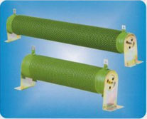
The braking resistor dissipates heat, so it should not be installed in the immediate vicinity of appliances and devices that cannot tolerate heat. Fan cooling possible. There are aluminum and ceramic resistors, as well as resistor assemblies for high power ratings.
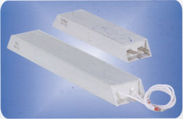
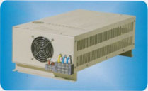
Aluminum brake resistors of the PRXLG series are produced for operation with Pn = 0.12..0.5 kW, nominal resistance 60 - 300 Ohm. Braking ceramic resistors of the BR series are produced for a wide power range Pn = 0.12..3 kW, resistance 27 - 300 Ohm. Blocks of brake resistors of the BRC series are designed for operation Pn = 5..25 kW, resistance 3 - 20 Ohm.
Thus, two-pole three-phase motors are no different from motors with four, six, eight or ten poles. Essentially, the combined magnetic field rotates inside the stationary stator and induces a current in the spinning rotor which spins the attached load. Thus, electrical energy is converted into useful mechanical energy in the form of motor shaft torque and angular velocity.
The motor windings already present for motor control are fed from a DC source to create a stationary magnetic field. This stationary field provides static force on the rotor, causing it to stop. Below is a discussion of two common types of DC brakes that work well together to form a complete braking system.
Ceramic braking resistors from 50 to 2500 W
 |
| Power, W | Dimensions, mm | ||||||||||
|---|---|---|---|---|---|---|---|---|---|---|---|
| L1(±2) | L2(±5) | L3(±3) | D(±2) | B | B1 | H | H1(±3) | N | d | O | |
| 50 | 102 | 124 | 146 | 28 | 6.5 | 28 | 28 | 61 | 10 | 4.5 | 1.2 |
| 60 | 102 | 124 | 146 | 28 | 6.5 | 28 | 28 | 61 | 10 | 4.5 | 1.2 |
| 80 | 152 | 174 | 196 | 28 | 6.5 | 28 | 28 | 61 | 10 | 4.5 | 1.2 |
| 100 | 182 | 204 | 226 | 28 | 6.5 | 28 | 28 | 61 | 10 | 4.5 | 1.2 |
| 120 | 182 | 204 | 226 | 28 | 6.5 | 28 | 28 | 61 | 10 | 4.5 | 1.2 |
| 150 | 195 | 217 | 239 | 40 | 8 | 40 | 41 | 81 | 12 | 5.5 | 2.0 |
| 200 | 195 | 217 | 239 | 40 | 8 | 40 | 41 | 81 | 12 | 5.5 | 2.0 |
| 300 | 282 | 304 | 326 | 40 | 8 | 40 | 41 | 81 | 12 | 5.5 | 2.0 |
| 400 | 282 | 304 | 326 | 40 | 8 | 40 | 41 | 81 | 12 | 5.5 | 2.0 |
| 500 | 316 | 338 | 360 | 50 | 8 | 50 | 45 | 101 | 16 | 6 | 2.0 |
| 600 | 345 | 367 | 389 | 60 | 8 | 40 | 41 | 119 | 12 | 5.5 | 2.0 |
| 750 | 316 | 338 | 360 | 60 | 8 | 50 | 45 | 119 | 16 | 6 | 2.0 |
| 1000 | 300 | 325 | 350 | 70 | 8.5 | 60 | 60 | 130 | 16 | 6 | 2.0 |
| 1200 | 415 | 440 | 465 | 70 | 8.5 | 60 | 60 | 130 | 16 | 6 | 2.0 |
| 1500 | 415 | 440 | 465 | 70 | 8.5 | 60 | 60 | 130 | 16 | 6 | 2.0 |
| 2000 | 510 | 535 | 560 | 70 | 8.5 | 60 | 60 | 130 | 16 | 6 | 2.0 |
| 2500 | 600 | 625 | 650 | 70 | 8.5 | 60 | 60 | 130 | 16 | 6 | 2.0 |
Aluminum braking resistors from 40 to 500 W
Electronic regenerative brakes work primarily by slowing down the systems they are applied to. They take dynamic energy from a spinning rotor and load, convert it into electrical energy, and feed it back into the brake power line. Alternatively, in the same system, the regenerated electricity can be dissipated as heat in a resistor or rheostatic brake.
Basic questions on frequency converters
The problem with regenerative braking is that as the load slows down, the energy recovery obviously decreases with it, and the braking force decreases until backup brakes, such as an injection brake, are needed to bring it to a complete stop. Regenerative brake issues also include heat transfer limits and transistor size; both limit the braking torque. When used, rheostatic braking resistors must have sufficient resistance to the braking current limit as well as a specified power to ensure braking cycles.
 |
Resistor power, W | Overall dimensions, mm | Weight, g |
|---|---|---|---|
| 40 | 80*40*20 | 68 | |
| 60 | 115*40*20 | 103 | |
| 80 | 140*40*20 | 128 | |
| 100 | 165*40*20 | 153 | |
| 120 | 184*40*20 | 170 | |
| 150 | 215*40*20 | 200 | |
| 200 | 167*60*30 | 157 | |
| 300 | 215*60*30 | 205 | |
| 400 | 268*60*30 | 258 | |
| 500 | 335*60*30 | 325 |
Resistor assemblies with power from 1 to 20 kW
While discs are not usually selected based on brake requirements, braking frequency and amount of braking are important considerations when braking frequently. If the braking is particularly heavy, the brakes are better protected at a constant rating of about 150% of the peak braking level, as this reduces thermal stress fatigue caused by cycling.
Disc manufacturers usually offer regenerative brakes with low wattage retraction brakes, or none at all. However, when the load brake is important, a drive with these brake functions is needed. Regenerative braking is often standard on variable speed drives. However, regenerative line braking requires a drive with a transistorized front end and is only cost effective for fast cycling processes such as centrifuges or dynamometers.
 |
|
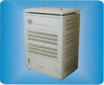
Resistor assemblies with power from 20 to 200 kW
Food alternating current changes to impulse current DC current that flows in one of the motor windings used for braking. Since braking energy is dissipated in the motor itself in DC mode, a deceleration mechanism such as regenerative brakes is required to reduce motor wear. Otherwise, the required braking current is too high, risking saturation of the stator windings and overheating.
How to choose a braking resistor?
Commonly used with three-phase motors, injection brakes are either added to existing motor control circuits or integrated into new motor control applications. The current, as well as the subsequent injection braking force, are functions of the applied DC voltage and the properties of the stator winding; this is key when connecting DC to multiple motors or motors with six or nine wires for multiple windings as their properties vary.
 |
|
Price list
High currents affect line voltage, so power systems need good voltage regulation during deceleration. In addition, injection brakes are usually sized for the fully loaded motor current and voltage. For safety reasons - DC injection brakes generate many thermal energy circuits that are usually included in the thermal and overload circuit of the motor. Thus, when the engine is critically overheated, the brakes are not applied.
When DC injection braking power is supplied through the motor circuit, the brakes either require their own fuses or high-risk circuit fuses. However, with this integrated setting, the brakes must be locked when starting or running the engine. Otherwise, the resulting short circuit will cause havoc with the brake, motor branch circuit and other device. In addition, injection DC brakes should not be connected to manually operated motor branch circuits, as they are more intended for use with electromechanical branch circuits with a three-phase contactor.
| Name | Rated power, W | Resistance, Ohm | Cost with VAT, rub |
|---|---|---|---|
| Aluminum brake resistors | |||
| PRXLG 0120.150 | 120 | 150 | 600r. |
| PRXLG 0200.100 | 200 | 100 | 1 000 rub. |
| PRXLG 0300.060 | 300 | 60 | 1 100 rub. |
| PRXLG 0200.300 | 200 | 300 | 800r. |
| PRXLG 0300.150 | 300 | 150 | 1 100 rub. |
| PRXLG 0500.100 | 500 | 100 | 1 300 rub. |
| Ceramic brake resistors | |||
| BR 0120.150 | 120 | 150 | 500r. |
| BR 0200.100 | 200 | 100 | 600r. |
| BR 0300.060 | 300 | 60 | 900r. |
| BR 0200.300 | 200 | 300 | 600r. |
| BR 0300.150 | 300 | 150 | 900r. |
| BR 0500.100 | 500 | 100 | 1 100 rub. |
| BR 1000.080 | 1000 | 80 | 2 100 rub. |
| BR 1000.060 | 1000 | 60 | 2 100 rub. |
| BR 1000.050 | 1000 | 50 | 2 100 rub. |
| BR 1500.040 | 1500 | 40 | 2 900 rub. |
| BR 3000.032 | 3000 | 32 | 4 500 rub. |
| BR 3000.027 | 3000 | 27 | 4 500 rub. |
| Braking resistor blocks | |||
| BRC 05К.20 | 5000 | 20 | 15 300 rub. |
| BRC 05K.16 | 5000 | 16 | 15 300 rub. |
| BRC 10К.13 | 10000 | 13 | 24 000 rub. |
| BRC 10К.10 | 10000 | 10 | 24 000 rub. |
| BRC 15К.08 | 15000 | 8 | 29 200 rub. |
| BRC 15K.07 | 15000 | 7 | 29 200 rub. |
| BRC 15К.05 | 15000 | 5 | 29 200 rub. |
| BRC 20K.04 | 20000 | 4 | 49 600 rub. |
| BRC 25К.03 | 25000 | 3 | 54 500 rub. |
We advise you to read
 Psychological characteristics of children in adolescence
 Transferring a child to another school - the procedure and necessary documents Whether to transfer a child to another school
, diagnosis, treatment Treatment of urogenital chlamydia") Chlamydia urogenital - description, causes, symptoms (signs), diagnosis, treatment Treatment of urogenital chlamydia
Chlamydia urogenital - description, causes, symptoms (signs), diagnosis, treatment Treatment of urogenital chlamydia The benefits and significance of hydroamino acid threonine for the human body L threonine what

