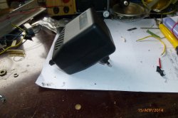
Ever since my first soldering with acid flux, I've been thinking about a soldering fan. After radio assembly practice (there they clearly explained the need for hood when soldering any flux / solder) it was decided: the hood should be! Just in time, the VN-2 fan came to hand.
But it turned out that when connected directly to the network, the fan is very noisy, and I would like to control the draft of the future hood. Need a regulator!
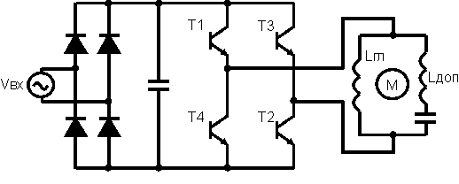
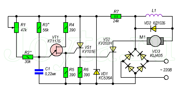
Scheme of the speed controller of a single-phase asynchronous motor on a transistor D209L
Having searched a little on the net, I chose the scheme of the so-called "interference-free" regulator:Having assembled the circuit, I was convinced of its suitability for adjusting the speed of a single-phase induction motor(as in VN-2). But after a short circuit at the exit to the country of eternal hunting, my only KT840 is sent and neon light bulb, which I connected without a resistor. Prices for KT840 did not please me at all. Deciding to save a scholarship, I found an analogue transistor from a burnt computer PSU - D209L. With this transistor, the circuit had to be slightly changed:
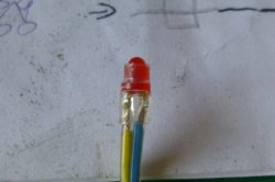
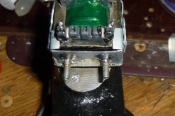
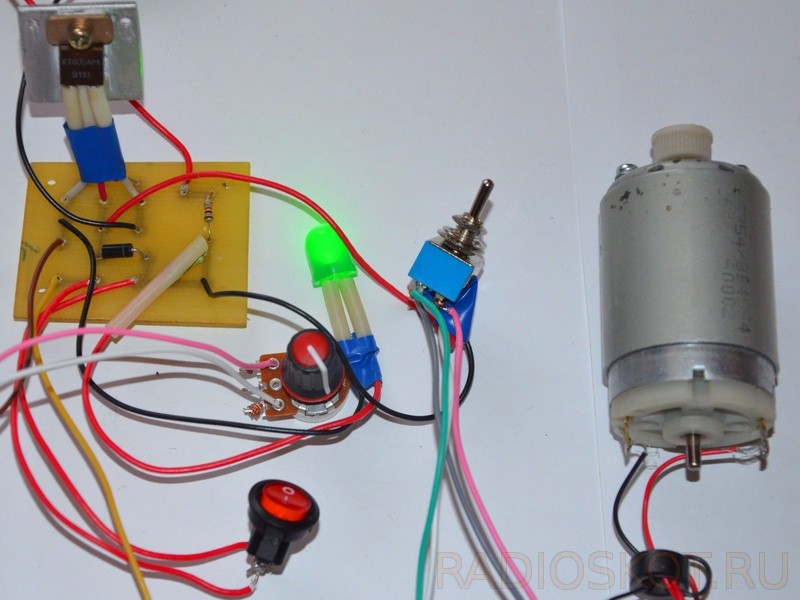
I decided to add some indication, and put LEDs on the input and output of the regulator. First, I also tested the new circuit on a surface mount, and then I decided to assemble it in a normal case, which I purchased on the radio market:

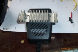
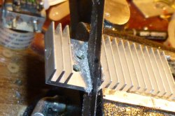
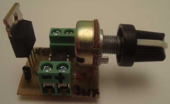
I immediately took care of the radiator for the transistor. The radiator had to be adjusted a little with a hacksaw and a file:
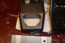

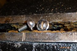
To attach the radiator to the case, I used homemade screws M3 with a wide hat (soldered on the washer to the screw):

This is how it will look from the outside:

Now the controls:
Trying on:

Drill holes and insert parts:

With the diameter of the holes for the LEDs, I missed a little, I had to pack it in a transparent heat shrink:
PS: transparent heat shrink is the best of all that I have seen on the Kiev radio market, it does not swell or burn when shrinking, and when two layers are joined, they fuse, and a monolithic tube is obtained.
Transformer
I used a small-sized 220/6 Volt, 100mA. I also "packed" it in a tin frame for ease of installation. The body of the old CD-Rom and champagne wire (scientifically - muselet) served as the material for the frame.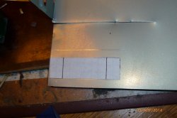

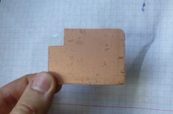
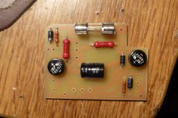
Printed circuit board
To make the board, I first cut out a template from cardboard so as not to make a mistake in size and then adjust the finished board with a file:
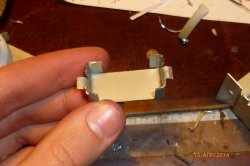
According to the template, I cut out a PCB board with scissors for metal:
I draw the board manually with a stencil using a stencil, having previously applied dots in the places of future holes with a home-made center punch from a cutter.


I drew the tracks themselves with the help of a “reisfeder” from a rod extended from a pen with a pipette, very convenient (does not break like a glass pipette). I “bake” the finished tracks with a gas burner: I experimentally found that my zaponlak from such shock drying becomes generally “oak”, which is suitable for my etching technique, which is described below. Roasting process:
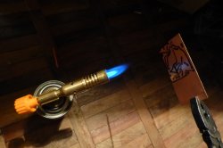
Important: If there are fingerprints/dirt on the copper during firing, they will remain on the etched board. Therefore, I seal the pure textolite with adhesive tape for the time of cutting / punching and peel it off only when I draw the tracks.
Etching
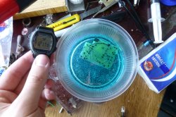
I recently discovered a simply fantastic method of etching circuit boards: citric acid!Recommended method for preparing pickling solution:
In 100 ml of pharmacy 3% hydrogen peroxide, 30 g of citric acid and 5 g of salt are dissolved. This solution should be enough to pickle 100 cm2 of copper, 35 µm thick.
Salt in the preparation of the solution can not be spared. Since it plays the role of a catalyst, it is practically not consumed in the etching process. Peroxide 3% should not be further diluted. when other ingredients are added, its concentration decreases.
The more hydrogen peroxide (hydroperite) is added, the faster the process will go, but do not overdo it - the solution is not stored, i.e. is not reused, which means that hydroperite will simply be overused. An excess of peroxide is easily identified by abundant "bubble" during pickling.
However, the addition of citric acid and peroxide is quite acceptable, but it is more rational to prepare a fresh solution.
I etched my board in about 12 minutes!
Further, all without "amateur":


Final Assembly of the Regulator
Parts outside the board "receive" the wires in heat shrink, some of these parts have to be soldered from the side of the tracks.The speed controller of the electric motor is a device that gradually increases or decreases the speed of the motor. With the help of such a device, it is possible to keep the speed of rotation of the motor constant even under unstable loads. It will prolong life household appliances: power tools, kitchen helpers and others. The regulation process occurs due to pulse modulation or voltage changes. The regulator is designed to control the speed of non-DC motors by changing the average voltage level by means of phase stabilization using an electronic circuit.
Device device
This device is quite simple to operate, but has a rather complex structure. The 220V electric motor speed controller has the following components: a bridge and two arms, the left one being a voltage divider, and the right one being a thyristor and a motor. The thyristor junction is located in the diagonal of the bridge. Its signal is a combination of signals that take place in antiphase of the voltage that is set by the resistor and back EMF motor. When the voltage level is constant, the bridge is in equilibrium, the speed of rotation of the motor is unchanged. When the load on the motor shaft increases, its speed decreases and the back-EMF level drops, as a result of which the bridge loses balance. Thus, the signal that is directed to the thyristor junction grows, in the next phase of operation it opens faster, which increases the power going to the motor.
Functions and Specifications
The main functions of the 220V electric motor speed controller are:
- Management and control of the number of revolutions of an electric type engine;
- Power supply function;
- Increasing the service life of electrical appliances and tools.
Specifications , characteristic of regulators, determine the success of their work:
- Designated AC voltage - describes the voltage level that the device is designed to work with. The unit of measure is Volt. For example, 220V.
- Maximum load current. A property that characterizes the indicator, the excess of which disables the speed controller. Measured in amperes.
- The output load current is the level of electricity after the action of the regulator.
- Power variation spectrum - characterizes the range between the lowest and highest power that the device can withstand.
In addition to technical, electric motor speed controllers also have overall characteristics . Such as: weight, size (length, width, height).
Buying an electric motor speed register
It is not difficult to buy an electric motor speed controller. This can be done in specialized stores, where consultants will be happy to provide you with all the necessary information. An easier option is to order the device in the online store. In any case, when choosing any regulator model, it is worth considering the disadvantages and advantages of the device. A significant drawback of many motor speed controllers is the use of an overly sensitive thyristor in it: it responds to currents less than 100 μA. A feature of the regulators are expensive frequency converters, which are produced in small quantities and not by all manufacturers.

Device manufacturers
Today on the market there are a large number of motor speed controllers from various manufacturers, such as: Italtecnica, VTS Euroheat, EUROHEAT and many others. They offer consumers models of different power, design, principle of operation.
Installation and connection of the motor speed controller
The installation and connection of the speed controller is largely determined by what it was purchased for. It is natural that the regulator for a food processor, electric drill, washing machine is connected in different ways. Yes, and it is worth installing them only by accurately choosing the right place for this. So, when purchasing such a regulator, it is best to contact a specialist to install and connect it. Or, if you are confident in your abilities, you can study a specific scheme or watch a video tutorial.
The electric motor speed controller is an indispensable device in everyday life that controls the speed and frequency of the motor. Its advantage is that it will extend the life of your electrical appliances by providing and maintaining the correct constant voltage level. Also, this device can serve as a power source. The motor speed controller must be in your home!
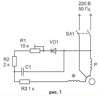
This is a device designed to perform the function of smoothly increasing or decreasing the speed of rotation of the electric motor shaft. Adjustment can be carried out by the method of pulse-width modulation and the method of changing the phase voltage.
Using Pulse Width Modulation
For controlling and adjusting the number of revolutions of the electric motor asynchronous type, you can use a switching voltage regulator (inverter). It will act as a power source. It is based on the use of a pulsed PWM controller brand TL494. The motor supply voltage after the PWM controller will change according to the change in speed. Using this method, a greater economic effect is achieved, the device is quite simple and at the same time increases the efficiency of regulation.
The figure above shows a diagram of using a PWM controller for a three-phase asynchronous motor connected through a capacitor to a single-phase network.
This method, despite its effectiveness, has two significant drawbacks - these are:
- the impossibility of reverse motor control without the use of additional switching devices;
- frequency converters used in the controller are expensive and are produced by a limited number of manufacturers.
Block for controlling and regulating the speed of rotation of electric motors by changing the phase voltage
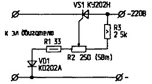
There are several types of control units manufactured industrially. They are used for single-phase asynchronous motors, the control limits are from 25 to 100% of the power value, and from 1000 to 4000 rpm. These are devices marked PBC207, PB600/900.
The operation of the adjustment unit occurs when the average value changes AC voltage on the electric motor. It is produced using the method of phase voltage regulation, by changing the opening angle of semiconductor devices (thyristors, triacs, etc.), using which the circuit was assembled.
The unit is controlled by using an external variable resistor. In the event that the power is less than 25%, the engine turns off and goes into standby mode.
Operation is controlled by a light indicator. Disabled engine status - red flashes occasionally. The engine is running - the duty cycle of the indicator is proportional to the rotational speed (performance) of the engine.
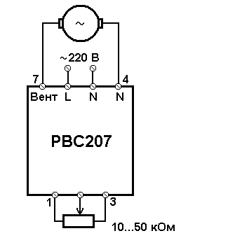
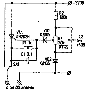
In the figure, the connection diagram of the RVS 207 regulator unit.
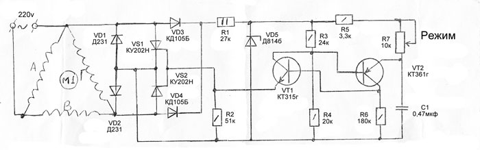
Induction Motor Speed Controller
In addition to samples of regulators, industrial designs of regulators, there is the possibility of independent production of speed controllers for brushless motors that are not inferior to industrial designs. The scheme is based on an example of an industrial production regulator, it can be assembled on its own.
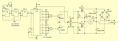
Pictured above circuit diagram brushless motor speed controller.
Adjust the number of rotations of the brushless shaft asynchronous motor also allowed when changing the value of the alternating voltage supplied to the motor.
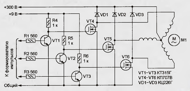
The regulator includes a master oscillator, it serves to change the frequency within the range of 50 - 200 Hz. The generator consists of a multivibrator, the operation of which is based on the K561LA7 microcircuit and the counter-decoder of the K561IE8 brand with a conversion factor of 8, it is responsible for generating control signals for the power field effect transistors of the half-bridge.
The circuit contains an output transformer T-1. It serves to decouple the half-bridge transistors.
The rectifier includes in its design diode bridge and doubling the supply voltage - capacitors with a large capacity.
The diode bridge is connected according to an unconventional scheme. C4 and R7 act as a damping circuit, it serves to smooth out voltage spikes that are a danger to VT4 transistors.
Recommendation: for a transistor switch control transformer, you can use a transformer from a television power supply. In this case, the type does not play of great importance, the main thing is that the primary winding consists of 120 turns of wire 0.7 mm2, the secondary consists of 2 windings independent of each other with the number of turns - 60, the wire used in the secondary winding is similar to the primary wire. Primary winding has a voltage of 2 x 12 V, the secondary winding is 12 V each.
It must be remembered that both secondary windings must have good insulation from each other, there is a high potential between the windings, it is 640 V, they are connected to the gates of transistor switches in antiphase.
Such a regulator can control the rotation of an asynchronous motor with a maximum operating power of 500 watts. In order to use the regulator to regulate electric motors of higher power, you need to use a larger number of power switches, and also change the capacitance of the capacitors for the supply filter in the direction of increasing, these are circuit elements C3 and C4. For the controller it is enough to use printed circuit board size 110 x 80 mm. The transformer controlling the power transistor switches is mounted separately from the regulator unit.
Write comments, additions to the article, maybe I missed something. Take a look at, I will be glad if you find something else useful on my site. All the best.
Asynchronous motors are used in machine tools and other equipment as electric drives to drive moving parts. Them wide application due to its simple design and relatively low cost. In these conditions, it is important to adjust the speed of the asynchronous motor, which allows you to work in the most different conditions. Standard schemes provide mechanical systems gears that are not very convenient under certain circumstances. Electrical control provides a number of advantages, despite all the difficulties associated with the connection.
Adjustment methods
Electric speed control allows you to accurately and smoothly adjust the required operating modes. This operation can be performed in several ways at once, related to changes in the parameters of the engine and electric current.
First of all, the voltage applied to the stator can change, as well as the auxiliary resistance of the rotor circuit. In addition, the speed of rotation is related to the change in the number of pole pairs and the frequency of the current.
With the last two methods, the change in rotation speed occurs without a significant reduction in power and loss of efficiency. All of them have their advantages and disadvantages, but, in general, they are successfully used for adjustment. These methods are considered the most suitable for induction motors with a design squirrel-cage rotor. It is these engines that are most often used in the manufacturing sector.
Features of frequency regulation
The most commonly used frequency regulation, which is performed using semiconductor converters. Their action is based on the features of asynchronous motors. Here the magnetic field rotates with a frequency related to the frequency that the mains voltage has.
In order for the engine to work efficiently, along with the frequency, it is necessary to change the voltage. The change in the voltage value is closely related to the load moment. Under constant load, the voltage will change in proportion to the frequency.
By using modern appliances, the speed of the asynchronous motor can be adjusted in the widest range. If necessary, you can apply the acceleration or deceleration of the units, depending on certain technological operations. To set the desired parameters, special control modules are used. Power switches are special high-power transistors. At high frequency switching current distortion are the most minimal.
How to determine the speed of an electric motor by winding
DIY birthday decor
Close... [X]
Such a box for things can be used in the kitchen, bathroom or other rooms for decorating the room with your own hands.
Cowboy pointed boots The principle of operation of a homemade castle is as follows. In one half of it is a permanent magnet. and in the other - a metal plate. One of them is attached to the door. The second one, with a removed metal plate, is equipped with a KEM-1 reed switch and is attached to the door frame. If the door is in the closed position, the two parts of the lock are pressed, the magnet acts on the reed switch, closing its contacts. If the door opens, the magnet leaves and the reed switch contacts open.
A battery, a computer system unit, even a laptop power supply - that's all best friends. I'm already silent about such good heating pads as my husband and I.
Take the filler and stuff the doll. When the stuffing is completely evenly distributed, sew the product. Handles must be sewn to the body almost near the neck.
From one pallet, sanded, impregnated and varnished, you get a garden table like a coffee table, on the left in fig. If there is a pair available, in just half an hour you can make a wall-mounted desktop-rack, in the center and on the right. Chains for it can also be woven yourself from soft wire, covered with a PVC tube or, better, heat-shrinkable. To fully raise the tabletop, a small tool is placed on a shelf of a wall pallet.
Well, if you fill a glass bowl, a vase, a candy bowl, a punch vessel or ordinary glasses with water, scattering sea pebbles at the bottom, and let the pill candles “free float”, we get a magical backlight for a romantic New Year. For a more interesting and unexpected effect, you can experiment with the color of the water. How are the spikes installed on the rubber?
Toys self made for children - it's beautiful, cheap and pleasant. Every child needs original and educational toys, but it is not always possible to purchase them. Today we will show you 5 examples of fun toys that you can make yourself. They can be made from cardboard, paper or wood. In general, be inspired and make your children happy more often.
For the base of this design, you can use thick plywood, and for its upper part - polycarbonate. Finding solar panels on the network today is also not a problem.
Attention! When joining panels, do not apply too much great effort, you may damage the seam.

This is how many knives the hostess should have in the kitchen so that the cooking process is always simple and enjoyable.

To make a do-it-yourself feeder, we need:
Wood calculation. Boards, called riveting, have biconvex sides to give the cooperage product a convexity. To make them like this, you need to take the lower part of the tree trunk and split it with a semblance of chopping firewood. If it is carefully cut, the natural integrity of the fibers will be violated, which is bad for such a product. Start immediately figured sawing not worth it - the logs need to be dried for 2 months. And dry not under the scorching sun, but in a dark, cool room.
How to weave bracelets from laces
The fact that most Christmas costumes for children preschool age easily sewn on the basis of overalls, can greatly narrow and facilitate creative search. If you learn to sew a jumpsuit - the basis for a New Year's costume and come up with (draw), make it yourself decorative elements to it, you can make amazing and rather interesting models of New Year's outfits for children. The main thing is to think over everything in advance to the smallest detail, arm yourself with knowledge on the topic - so that the result of the work will pleasantly surprise and please everyone.
Wardrobe design
Pictures 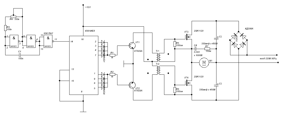 Do-it-yourself birthday gift for mom photo instruction
Similar news.
We advise you to read
 Psychological characteristics of children in adolescence
 Transferring a child to another school - the procedure and necessary documents Whether to transfer a child to another school
, diagnosis, treatment Treatment of urogenital chlamydia") Chlamydia urogenital - description, causes, symptoms (signs), diagnosis, treatment Treatment of urogenital chlamydia
Chlamydia urogenital - description, causes, symptoms (signs), diagnosis, treatment Treatment of urogenital chlamydia The benefits and significance of hydroamino acid threonine for the human body L threonine what

