The question of how to connect a single-phase electric motor very often arises in practice due to the high popularity of using such units for solving various household tasks.
Wiring diagram single-phase electric motor is quite simple and requires taking into account only one fundamental point: to ensure its performance, a rotating magnetic field is needed. If there is only a single-phase network alternating current at the time of starting the electric motor, it has to be formed artificially through the use of appropriate circuit solutions.
- Motor windings
- Capacitors
- Indirect Inclusion
- Conclusion
Motor windings
The design of any single-phase electric motor involves the use of at least three coils. Two of them are structural elements of the stator, connected in parallel. One of them is working, and the second performs the functions of a launcher. Their terminals are brought to the motor housing and are used to connect to the network. The rotor winding is short-circuited. Two of them will be connected to the network, the rest are used for switching.
To change the power, the working coil can be formed from two parts, which are connected in series.
You can visually identify the working and starting windings by the cross section of the wire: the first of them has it noticeably larger. You can measure the resistance with a tester by connecting it to the terminals: for the working winding, its value will be less. As a rule, the resistance of the windings will be no more than a few tens of ohms.
Features of the formation of torque
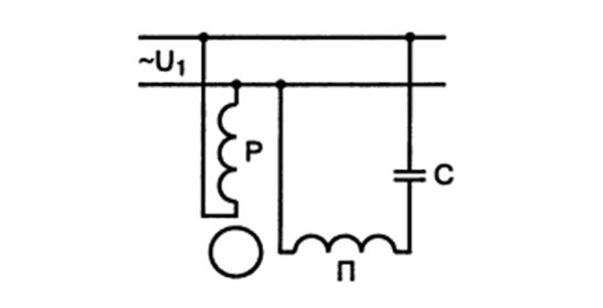
The magnetic field generated by the motor coils has a phase shift of 90 degrees. This is usually achieved through a capacitor that is connected in series with the start circuit. Possible connection options are shown in the figure below.
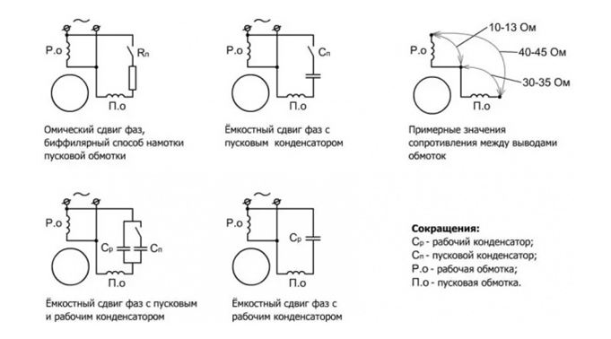
The starting coil can work continuously. A scheme based on its shutdown after reaching the nominal rotor speed is also acceptable. The constant connection of the starting winding complicates the design of the motor, but improves its performance. These differences do not affect the features of connecting to the network.
To simplify starting the engine with a working capacitor, an auxiliary capacitance is connected in parallel to it before supplying current from the network.
The single-phase electric motor allows simple means change the direction of rotation of the shaft to the opposite. To do this, the phase of the current coming from the network and flowing through the trigger circuits is reversed. This procedure is implemented by simply changing the order of switching on the starting winding when it is connected to the working winding.
Capacitors

Wiring diagram for single-phase capacitor motors: a - c working capacity Cp, b - with working capacity Cp and starting capacity Sp.
The electric motor can be equipped with two types of capacitors. The presence of a capacitance connected in series by the trigger winding and passing a current through itself to shift the phase is mandatory. Its value is taken from the passport data of the electric motor and duplicated on its nameplate.
In the absence of a capacitor of the required capacity, it is permissible to use any other with a similar rating. If the downward deviation is too strong, the engine may not start to rotate without manually scrolling its shaft, and then it will not develop the necessary power. If the capacity is significantly exceeded, strong heating will begin.
The capacity of the additional starting component is selected two to three times higher than that of the main one. This value provides the maximum starting torque.
To turn on the trigger element, both a regular button and more complex circuits can be used.
Indirect Inclusion
The main component of the indirect connection circuit is a magnetic starter, which is included in the gap between the power network output and the electric motor.
The power contacts of this block are designed as normally open. The magnetic starter, in terms of the maximum current flowing through it, belongs to one of the seven normalized groups. Due to the low power of single-phase electric motors, a device of the first group is usually sufficient, the maximum switching current of which is 10 A.
The control part of the coil is designed to be connected to networks with different voltages. The most convenient is a magnetic starter controlled by 220V AC.
Features of the use of a magnetic starter
In the control part of the device, several pairs of contacts are provided, on which the relay automation circuit is assembled. One of them is always normally closed, and the second is normally open.
For the "Start" button, a normally open contact is considered to be working, and for the "Stop" button, a normally closed element is used.
When you connect the device in question, several types of connections are made.
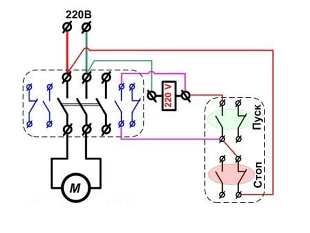
The phase, along with the input terminal, is also connected to the contact input of the "Stop" button, and the zero is connected to the input terminal of the coil, which ensures the flow of control current through it.
The active contact of the "Start" button with the engine running is shunted by a similar coil element. To form this circuit, two additional connections are made, the diagram of which is shown in the figure above:
- the output of the working contact of the "Stop" button is connected in parallel with the contacts of the output of the "Start" button and the input of the control coil;
- the output of the normally open contact of the control coil is connected in parallel with its output terminal and with the input of the working contact of the "Start" button.
Conclusion
The process of connecting a single-phase electric motor to a 220v network is not very complicated and in fact requires only desire, a minimum set of simple tools, a wiring diagram and accuracy in work. From Supplies only wires are needed. Because of the danger short circuit and large currents flowing through the motor windings, it is imperative to comply with safety requirements and do not forget about the old, but very effective rule: "Measure seven times, cut once."
25. SCHEMES OF INCLUDING SINGLE-PHASE ASYNCHRONOUS MOTORS
One phase motors have two windings on the stator: working and auxiliary. The latter is switched on only at the time of starting and therefore is called starting. The working winding is also called the main phase, and the starting winding is called the auxiliary. Single-phase motors are powered from a single-phase network.
Single-phase motors are widely used, in which two windings (two phases) are constantly on. Such motors, according to the principle of operation, are two-phase, but since they are included in single-phase network, and in the auxiliary phase of such motors there is usually a permanently connected capacitor, then they are called single-phase capacitor motors, in contrast to single-phase motors with a starting winding.
The rotors of single-phase motors, including capacitor ones, are in most cases short-circuited.
The starting winding of a single-phase motor has a high current density, it is switched on only for the start-up period and, upon reaching a speed close to the nominal one, must be turned off. The time spent under current is limited. So, for example, for micromotors of a single series such as AOLB, AOLG, this time in order to avoid overheating of the winding should not exceed 3 s. Frequent starts can lead to overheating of the starting winding.
For micromotors of a single series, three starts in a row from a cold state and one from a hot state are allowed, provided that the winding stay time at start is 3 s.
The starting winding is turned off by a centrifugal or push-button switch, an overcurrent relay, a bimetallic thermal relay and other devices.
To change the direction of rotation of a single-phase motor, it is necessary to switch the outputs of one of the stator phases.
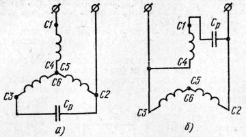
Depending on the type of starting element included in the auxiliary phase, single-phase motors with starting resistance are distinguished (Fig. 58, a) and with starting capacity (Fig. 58, b).
The starting resistance can be external, that is, located outside the winding and connected in series with it, or introduced. Motors with resistance introduced into the auxiliary winding are also called motors with increased starting phase resistance. In this case, the starting winding is usually made with bifilar coils with reduced cross-section wire. Motors with starting capacitance or external resistance are called single-phase motors with starting elements.
single phase capacitor motors have either two containers - starting and working (Fig. 58, in), or only one - working (Fig. 58, G). The starting capacitor is switched on only for the starting period and serves to increase the starting torque.
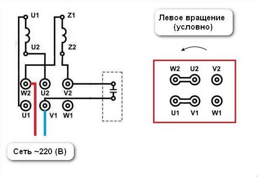
In recent years, universal asynchronous micromotors have been produced, designed to operate both from a three-phase and from a single-phase network. When included in three-phase network the phases of the motor winding are switched on in a triangle or a star, depending on the rated voltage of the network. Motors are connected to a single-phase network according to one of the schemes (Fig. 59). With such schemes, a single-phase network must correspond to a larger rated voltage of the motor. So, for example, if the engine has a rating
Rice. 58. Schemes of single-phase asynchronous motors: a - with starting resistance, b - with starting capacity, c - with starting and working capacities (capacitor motor), d - with working capacity: A - main winding, B - auxiliary winding, R p - starting resistance, C p - starting capacity, C p - working capacity
Rice. 59. Switching schemes three-phase winding into a single-phase network: a - when connecting the windings into a star with a parallel-connected capacitance, b - when parallel connection main and auxiliary windings
nal voltage 127/220 V, then in single-phase mode it must operate at a voltage of 220 V.
single phase asynchronous motor- low-power mechanism up to 10 kW. However, due to its compactness and features of action, its use is very large.
Scope of application: household appliances with single-phase current. single phase asynchronous electric motors used for refrigerators, centrifuges, washing machines. Often used for low power fans.
Single-phase appliances are also used in industry, but not as often as multi-phase units.
- Types of single-phase motors
- Principle of operation
Device and connection diagram of blood pressure
Interesting! A three-phase asynchronous motor can be used for single-phase operation. You need to do a calculation first.
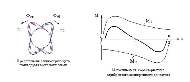
The stator has two electrical windings. One of them is working, which is the main one. The second launcher is also needed to launch the device. The difference between single-phase motors is the absence of an intake moment. The rotor resembles a squirrel cage in structure. Single phase current produces a magnetic field. It consists of two fields. Turning on the device, the motor rotor is stationary.
The calculation of the resulting moment with a stationary rotor underlies the magnetic fields that form two rotating moments.
Opposite moments are denoted by M.
n - speed
If the fixed part is activated, then a torque will come. Due to its inaccessibility at startup, the engines are equipped with an additional starting device.
The difference between single-phase asynchronous motors and three-phase ones is the features of the stator. The grooves have a two-phase winding. One will be the main or working, and the second is called the launcher.
The magnetic axes are in relation to each other at 90 degrees. The included working phase does not cause the rotation of the rotor due to the fixed axis of the magnetic field.
There are special programs for calculating the stator windings.
Types of single-phase motors
Distinguish bifilar and condenser mechanism.
- bifilar start
The bifilar winding is not used in continuous operation. Otherwise, the efficiency value decreases. Gaining momentum, it breaks off. The start winding is switched on for a few seconds. Calculate work by 3 seconds up to 30 times in 60 minutes. Exceeding starts can lead to overheating of the coils.
- capacitor start
The phase is split, the auxiliary winding circuit is switched on during start-up. To achieve the starting torque, it is necessary to create a circular magnetic field. The use of a capacitor provides the best Starting torque. Motors with capacitors included in the circuit are capacitor motors. They work on the basis of the rotation of the field of magnets. A capacitor device has two coils that are always energized.
Principle of operation
The principle of operation is based on a squirrel-cage rotor. The magnetic field is represented as two circles with opposite sequences, i.e. the fields rotate in different sides, but at the same speed. If the rotor is pre-dispersed in the right direction, then it will continue to rotate in the same direction.
![]()
Therefore, single-phase HELL is started by pressing the start button. This causes excitation in the stator. Currents activate the magnetic field to rotate, and magnetic induction occurs in the air gap. In a few seconds, the acceleration of the rotor is equal to the rated speed.
By releasing the intake button, the engine switches from two-phase to one-phase mode. The single-phase mode is maintained by the component of the alternating field of the magnets, which rotates faster than the rotor due to slip.
To improve the operation of a single-phase AD, a centrifugal switch and a relay with break contacts are built in.
The centrifugal switch interrupts the start of the stator winding on the machine if the rotor speed is rated. A thermal relay disconnects the two-phase winding from the network when they overheat.
A change in the direction of rotor rotation is obtained by changing the direction of the current in any of the phases of the winding at start-up. This is achieved by pressing the start button and rearranging two or one metal plates.
To form a phase shift, you must add a resistor, inductor, or capacitor to the circuit. All of them are phase-replacing elements.
During the engine start, two phases work, and then one.
Advantages:
- greater motor ability due to the lack of a collector;
- small size and weight;
- inexpensive cost in comparison with multiphase;
- power supply from a sinusoidal network;
- simple design due to the squirrel-cage rotor.
Flaws:
- lack or low starting torque, as well as low efficiency;
- narrow speed range.
Advice! To purchase a quality single-phase motor, choose a reliable manufacturer. For example, AIRE, Siemens, Emod. Check for documents.
The cost of a single-phase asynchronous motor depends on its power. The average price varies from 2.5 thousand rubles to 9 thousand. You can buy single-phase asynchronous motors in stores or on the Internet.
With the correct calculation and principle of operation, a single-phase asynchronous motor will serve for a long time and efficiently.
How to determine the working and starting windings of a single-phase electric motor
Hello, dear readers and guests of the Electrician's Notes website.
I am often asked about how you can distinguish between a working winding and a starting winding in single-phase motors when there is no marking on the wires.
Every time you have to explain in detail what and how. And today I decided to write a whole article about it.
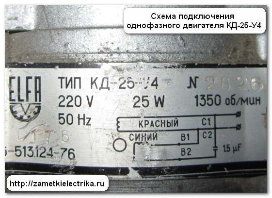
As an example, I will take a single-phase electric motor KD-25-U4, 220 (V), 1350 (rpm):
- KD - capacitor motor
- 25 - power 25 (W)
- U4 - climatic version
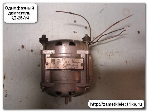
Here is his appearance.
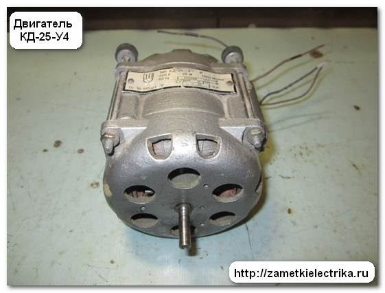
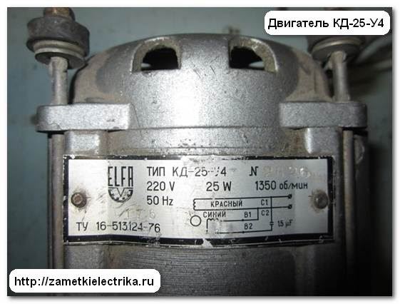
As you can see, there is no marking (color and digital) on the wires. On the engine tag you can see what marking the wires should have:
- working (С1-С2) - red wires
- starting (B1-B2) - blue wires
First of all, I will show you how to determine the working and starting windings of a single-phase motor, and then I will assemble a circuit for turning it on. But this will be the next article. Before you start reading this article, I recommend that you read: connecting a single-phase capacitor motor.
Visually look at the cross section of the conductors. A pair of wires with a larger cross section belong to the working winding. And vice versa. Wires with a smaller cross section belong to the starting wire.
Knowing the basics of electrical engineering. we can say with confidence: the larger the cross section of the wires, the lower their resistance, and vice versa, the smaller the cross section of the wires, the greater their resistance.
In my example, the difference in the cross section of the wires is not visible, because. They are thin and cannot be distinguished by eye.
2 . Measuring the ohmic resistance of windings
Even if the difference in the cross section of the wires is visible to the naked eye, I still recommend that you measure the resistance of the windings. Thus, at the same time, we will check their integrity.
To do this, use the digital multimeter M890D. Now I will not tell you how to use a multimeter, read about it here:
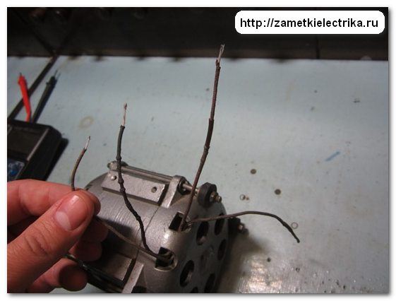
We remove the insulation from the wires.
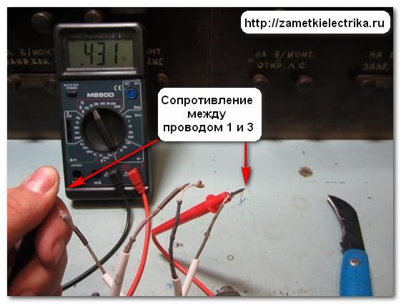
Then we take the probes of the multimeter and measure the resistance between any two wires.
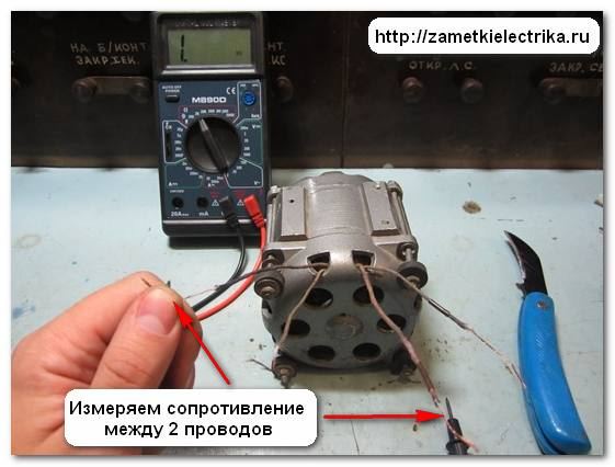
If there is no reading on the display, then you need to take another wire and measure again. Now the measured resistance value is 300 (Ω).
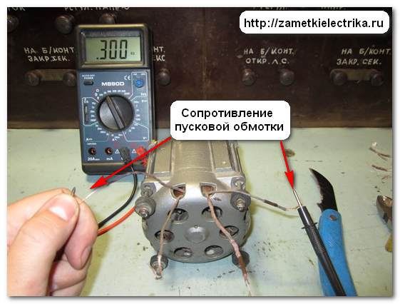
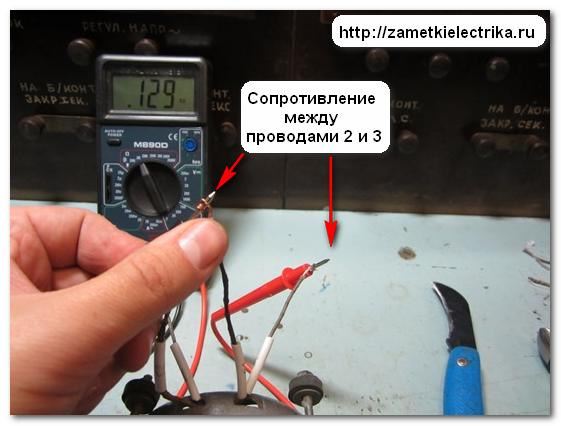
We found the conclusions of one winding. Now we connect the multimeter probes to the remaining pair of wires and measure the second winding. It turned out 129 (Ohm).
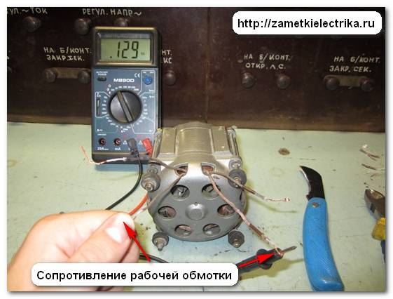
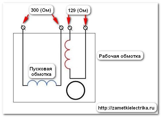
We conclude: the first winding is starting, the second is working.
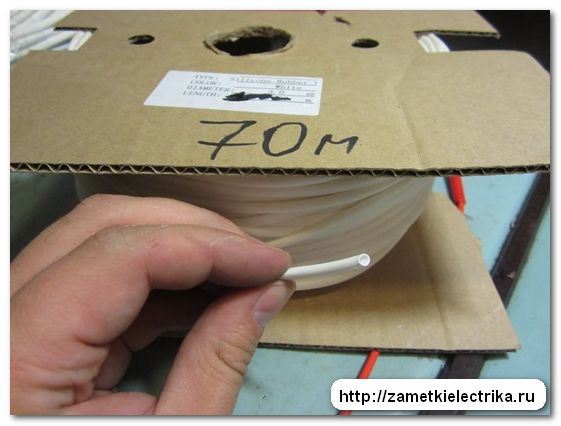
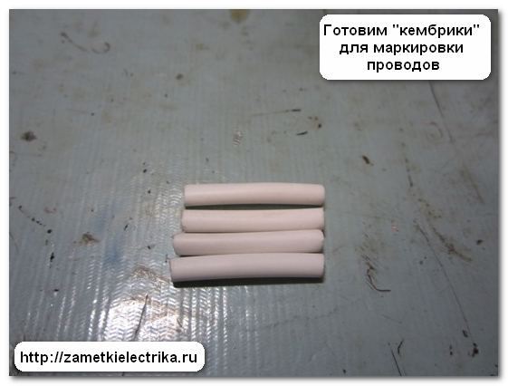
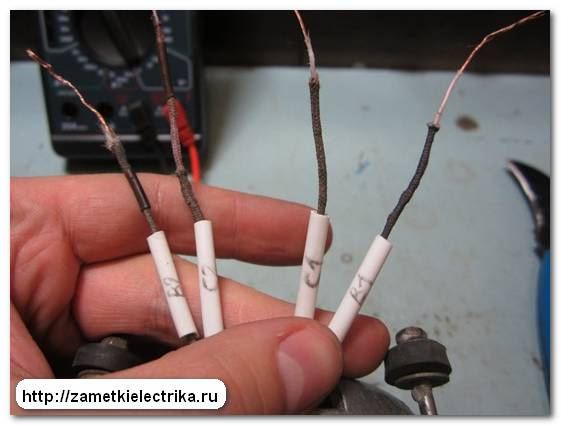
In order not to get confused in the wires when connecting the engine in the future, we will prepare tags (“cambric”) for marking. Usually, as tags, I use either insulating tube PVC, or a silicone tube (Silicone Rubber) of the diameter I need. In this example, I used a 3 (mm) silicone tube.

According to the new GOSTs, the windings of a single-phase motor are designated as follows:
The KD-25-U4 engine, taken as an example, digital marking done in the old way:
So that there are no inconsistencies between the wire marking and the circuit shown on the engine tag, I left the old marking.
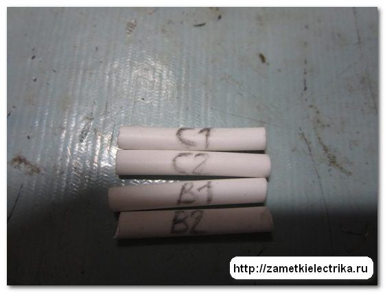
I wear wire tags. Here's what happened.
For reference: Many are mistaken when they say that the rotation of the motor can be changed by rearranging the mains plug (changing the poles of the supply voltage). It is not right. To change the direction of rotation, you need to swap the ends of the starting or working windings. The only way.
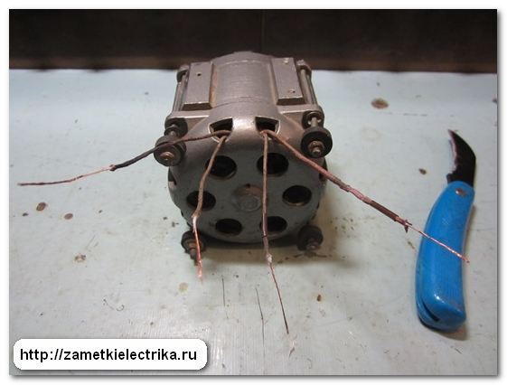
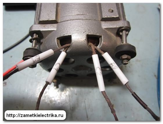
We considered the case when 4 wires are connected to the terminal block of a single-phase motor. And it also happens that only 3 wires are output to the terminal block.
In this case, the working and starting windings are connected not in the terminal block of the electric motor, but inside its housing.
How to be in that case?
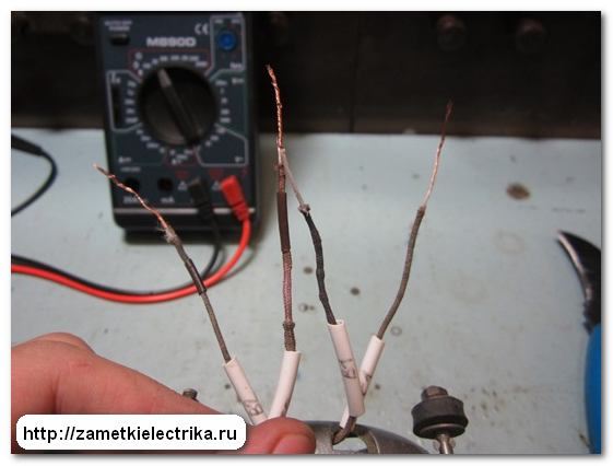
We do everything in the same way. We measure the resistance between each wire. Mentally label them as 1, 2 and 3.
That's what I did:
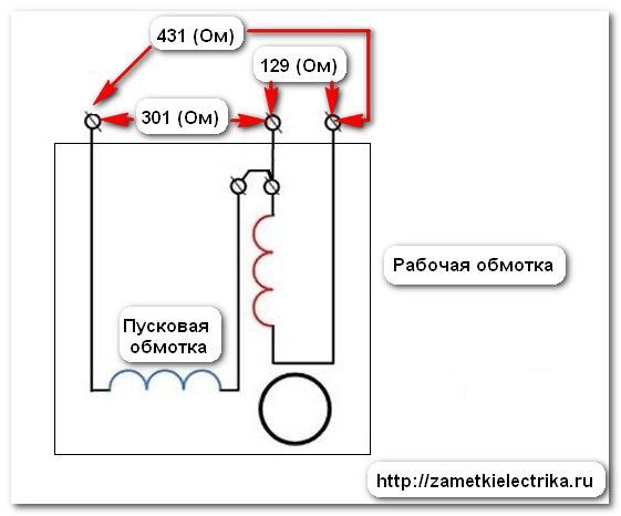
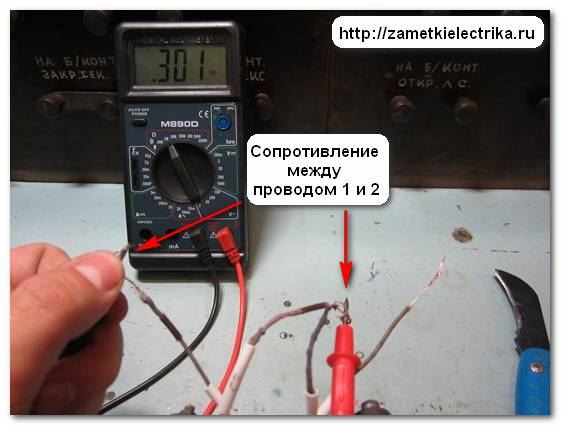
From this we draw the following conclusion:
- (1-2) - starting winding
- (2-3) - working winding
- (1-3) - starting and working windings are connected in series (301 + 129 = 431 Ohm)
For reference: with such a connection of the windings, the reverse of a single-phase motor is also possible. If you really want to, you can open the motor housing, find the junction of the starting and working windings, disconnect this connection and put 4 wires into the terminal block, as in the first case. But if your single-phase motor is capacitor, as in my case with KD-25, then its reverse can be done by switching the phase of the supply voltage.
P.S. That's all. If you have questions about the material of the article, then ask them in the comments. Thank you for your attention.
Good evening, Dmitry! I myself work as an electrician in ETL. I have a question about testing cable line from crosslinked polyethylene. Have you encountered this, what voltage was applied, what were the leakage currents, how long does it take to test one phase? Thanks in advance. if you can send your answer to me
mail.
Artem, hello. I wrote about testing cables made of cross-linked polyethylene in the comments in this article.
Hello Dmitry. but could you write an article in detail about oil switches, (solenoid, closing contactor, opening coil, its tests, measurements of characteristics) and also tests power transformer and his measurements. very necessary, there are nuances in the head.
SLV, I planned to write these articles, especially about different types drives (PE-11, PS-10, PE-21, etc.), about high-voltage oil and vacuum circuit breakers installed both in KSO chambers and on carriages, but I'm afraid that many visitors to the site will not be interested. I keep putting it off...
Hello Dmitry!
You explain everything very well, thank you very much! Could you clarify what is meant by circuit breakers, for example 6kA or 35kA, if they are designed for one operation current? And why do they have such a price difference?
Boris, values 4.5 (kA), 6 (kA), 10 (kA), etc. mean the electrodynamic resistance of the protection device in case of a short circuit in the network, i.e. show how the machine is resistant to short circuit. For a house (apartment), 4.5 (kA) is quite enough, because. the lines from the transformer substation to a residential building and from the ASU to apartments are quite long, they have a large active resistance, which leads to a decrease in short-circuit currents to values of 0.5-1.5 (kA), and more often even less.
I rummaged through the entire Internet, I can’t make it out, I read books at work, I can’t understand that’s all. By the way, could you tell me what the dielectric loss tangent of oil means, everyone talks about it at work and no one really knows for sure.)
And one more thing. Previously, many connected 3-phase motors to a single-phase circuit, but time has passed. Many are now buying ready-made single-phase ones. I had a table of the ratio of engine power to capacitor power. And then a friend asked me to connect a three-phase engine in the garage. I couldn't find it so I had to find it.
So, do you have such a table. They were in old textbooks on electrical engineering. If there is, please publish or send to my E-mail.
Sincerely, Nikolay.
Nikolay, read here. There is a calculation of the capacity of the working and starting capacitors depending on engine power.
Good afternoon! Please advise on the issue. Single-phase motor with capacitor start. From time to time the engine does not start - it hums. The capacitor bank is assembled from three MBGP-2 capacitors of 2uF 630V. Conders on the tester show full capacity. What threatens to increase the capacitance of capacitors? and what threatens to reduce their voltage from 630V to 450V? Thank you! winding resistance 50 ohms starting 20 ohms I don’t remember the working brand of the engine now.
Vadim, if the engine is buzzing, then there is no torque. This can happen for the following reasons: either the capacitors are out of order (absence or low capacitance), or an interturn occurs in one of the motor windings. It is better to start simple and replace the old capacitors with new ones. There is no need to increase the capacity, well, if only a little in one direction or another, but instead of 630 (V), you can safely use 450 (V).
Good afternoon. capacitors show nominal capacity. finding others was a problem for us. either a larger or smaller capacity, or the size is not suitable. or the price tag is not real and the delivery time. as I understand it, if I increase from six to almost seven microfarads, then there will be no special problems? The engine runs for fifteen seconds according to the condition. The problem with starting is not systematic. how to calculate interturn? on three-phase asynchronous, I know there is a device. Thank you.
Hello, experts. What if the direction of rotation of the motor changes unpredictably. But if I use a winding with a smaller cross section as a working one, then everything works fine, and when changing contacts, it changes the direction of rotation correctly, and works for about an hour without overheating. old USSR. One winding is 14 ohms, the second is 56 ohms.
Good day, today I undertook to start a household hood over the stove, the engine speed control unit has long been ordered to live long ... there are no problems with the light, but there are four wires from the electric motor, what to do with them. who to connect? I pulled out the pseudo-touch buttons, put them fixed, the KRONA GALA hood with three fan speeds ... Help me with the connection.
And how did you determine that the starting winding should have more resistance than working? based on what? please explain
Hello, I have a 2DAK71-40-1.0-u2 engine, there are four wires (black, red, gray, white), they all call each other, please tell me how to connect?
http://zametkielectrika.ru
§ 96. Single-phase asynchronous motors
Single-phase asynchronous motors are widely used at low powers (up to 1 - 2 kW). Such an engine is different from the usual three-phase motor the fact that it is placed on the stator single-phase winding. Therefore, any three-phase asynchronous motor can be used as a single-phase motor. The rotor of a single-phase asynchronous motor can have a phase or short-circuited winding.
A feature of single-phase asynchronous motors is the absence of an initial or starting torque, that is, when such a motor is connected to the network, its rotor remains stationary.
If, under the influence of any external force, the rotor is brought out of rest, then the engine will develop a torque.
The absence of an initial moment is a significant drawback of single-phase asynchronous motors. Therefore, these motors are always supplied with a starting device.
To obtain the initial torque, two windings can be placed on the stator, shifted one relative to the other by half the pole division (90 °). These windings must be connected to a symmetrical two-phase network, i.e., the voltages applied to the coil windings must be equal to each other and shifted by a quarter period in phase.
In this case, the currents flowing through the coils will also be shifted in phase by a quarter of the period, which, in addition to the spatial shift of the coils, makes it possible to obtain a rotating magnetic field. In the presence of a rotating magnetic field, the motor develops starting torque.
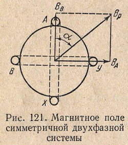
The simplest two-phase winding can be represented as two coils (Fig. 121), the axes of which are displaced in space by 90 °. If these coils having the same number turns, skip sinusoidal currents equal in magnitude and shifted in phase by a quarter of the period, i.e.
then magnetic fields these coils will also be sinusoidal and out of phase by a quarter of the period, i.e.
In this case, the vector AT A directed along the axis of the coil A-X, and the vector AT B- along the axis of the coil B - Y.
At any moment, the resulting magnetic field is equal to the geometric sum of the magnetic fields of the coils BUT and AT, i.e.
Therefore, with such a device, the resulting magnetic field of a two-phase winding has a constant value equal to the amplitude of the field of one phase.
Since in space the magnetic fields are mutually perpendicular, the angle formed by the resulting field with the axis of the coil AT, is determined from the condition
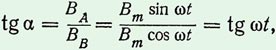
whence α = ω t i.e. the angle between the resulting field vector and the vertical axis changes linearly with time and hence this vector rotates at a constant speed
But in reality two-phase network usually absent, and the start of a single-phase motor is carried out by turning on two coils in one common single-phase network for them. Under such conditions, in order to obtain a phase shift angle between the currents in the coils, approximately equal to a quarter of the period, one of the coils (working) is connected to the network directly or with starting active resistance, and the second coil (starting) is connected through an inductive coil (Fig. 122, a ) or a capacitor (Fig. 122, b).
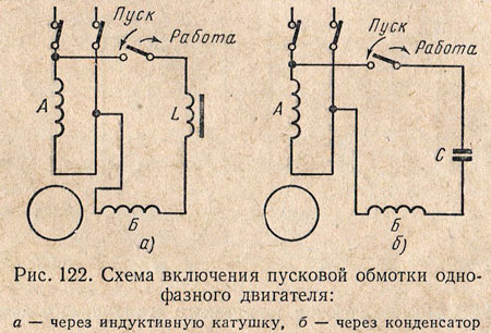
The starting winding is switched on only for the start-up period. At the moment when the rotor acquires a certain speed, the starting winding is disconnected from the network and the motor operates as a single-phase one.
The starting winding is switched off by a centrifugal switch or a special relay.
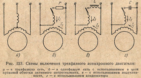
Any three-phase asynchronous motor can be used as a single-phase motor (Fig. 123, a). When a three-phase motor is operating as a single-phase, the working or main winding, consisting of two series-connected phases of a three-phase motor, is connected directly to a single-phase network, the third phase, which is a starting or auxiliary winding, is connected to the same network through a starting element - resistance (Fig. 123 , b), inductance (Fig. 123, c) or capacitor (Fig. 123, d).
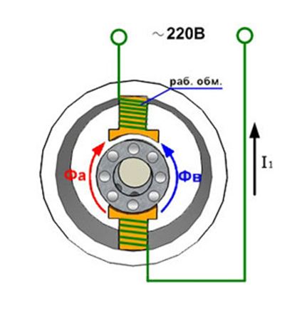
In single-phase low-power motors, short-circuited turns are used as the starting winding, which are placed on the stator poles. The stators of such motors are made with pronounced poles (Fig. 124) and the working winding is laid on the poles in the form of coils, like the excitation winding of a DC machine.
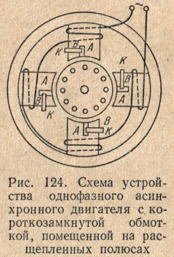
Each pole is divided into two parts, on one of which short-circuited coils are placed. In these coils, currents are created that prevent the passage of magnetic flux in part of the pole AT, as a result of which the magnetic flux in the part of the pole BUT reaches its maximum value earlier than in the part of the pole AT. These two out-of-phase flows excite a rotating magnetic field.
In short-circuited coils, additional losses occur, which reduces the efficiency of the engine. Therefore, this starting method is used only in engines of very low power (up to 100 Tue), where the value of efficiency is not paramount.
The capacitor motor is a single-phase asynchronous motor with two windings on the stator and squirrel-cage rotor(Fig. 125, a). In contrast to the method of starting single-phase motors through a capacitor, discussed above, in capacitor (two-phase) motors, the auxiliary winding is designed for a long passage of current and remains switched on not only when the motor is started, but also during operation. The presence of a rotating field during motor operation improves the performance of this motor in comparison with single-phase ones.
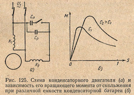
A circular rotating magnetic field in a capacitor motor will be obtained in the case of equality of the magnetizing forces of the two coils, and the magnetizing force of the coil To 2 must lead the magnetizing force of the coil To 1 to π/2 in time. This will be at some specific engine load.
When the load changes, the condition for obtaining a circular rotating field will be violated. In this case, in addition to the circular direct field, a reverse rotating field appears, which creates a braking torque, which reduces the torque of the machine.
With an increase in the capacitance of the capacitor, the current also increases, i.e., the motor load will increase, at which a circular rotating field will be created. Therefore, an increase in the capacity of the capacitor bank will cause an increase in the maximum torque of the machine, and maximum moment shifts to the area of \u200b\u200bhigh loads, i.e., large slips (Fig. 125, b).
As the capacitance increases, the starting torque of the motor also increases. However, increasing the capacity of the capacitor bank in the operating mode is undesirable, as this leads to a decrease in speed and lowers the efficiency of the engine. Therefore, capacitor motors are performed with two capacitor banks - with a permanently switched on or working capacity FROM p and starting capacity FROM n, included only for the period of starting the engine.
We advise you to read
, diagnosis, treatment Treatment of urogenital chlamydia") Urogenital chlamydia - description, causes, symptoms (signs), diagnosis, treatment Treatment of urogenital chlamydia
Urogenital chlamydia - description, causes, symptoms (signs), diagnosis, treatment Treatment of urogenital chlamydia The benefits and significance of hydroamino acid threonine for the human body L threonine that
 To wait or not to wait for a guy from the army For what reason can they be commissioned from the army
 Baked apples with cottage cheese Baked apples with cottage cheese

