1.
2.
3.
4.
5.
6.
7.
8.
9.
10.
11.
The procedure for laying a cable for specific purposes depends on where the work is planned. Cable lines in settlements that run between buildings are mainly laid in telephone ducts.
Laying of cable ducts in settlements
When cable laying is carried out within the city, then telephone sewerage will be required. In addition, existing cable ducts can be used. Often it is necessary to use an intermediate option. Most likely, when contacting the owner of the telephone sewer in the city for help in solving the problem, they will be given a technical condition for using the already existing telephone sewer. It usually prescribes a list of activities that should be performed so that the cable can be laid.Having the technical conditions, it will be necessary to order a cable duct project for its new laying or for a report from a design organization that has received SRO approval. When specifications a report is provided, then a list of necessary work and required materials will be written there, starting from the choice of pipes and ending with products for sealing.
To keep design and construction activities under control, you need to know how communication cable ducts are arranged.
Elements and nodes of cable ducting
The main elements are:- Pipes with a circular cross section, having an internal diameter of 100 mm and joined together. Their laying is carried out at a depth of 40-180 centimeters.
Pipeline sections are combined into a common structure by arranging reinforced concrete manholes with consoles inside them. They are required for cable placement. Devices are built depending on the configuration of the sites every 25-150 meters.
- Inspection wells, which are needed for carrying out activities with cables without opening the soil, and for placing cable sleeves in them.
- Telephone sewerage, which protects the cables placed in it from damage and makes it possible to repair, reconstruct and replace the laid lines on-line. As a rule, the construction of communication cable ducts is carried out either under pedestrian zones or along the edge of green spaces.
- For laying in buildings and premises, use a cable laid in rubber or vinyl hoses.
Telephone sewer pipes
Pipe for cable duct can be made of the following materials:- ceramics;
- asbestos cement;
- concrete;
- polyethylene having a smooth surface or corrugation on top;
- sand fiber;
- polyvinyl chloride.
In cases where underground structures are subjected to increased mechanical loads, instead of the above pipes, modules can be used, which are multichannels, which are made from high-density polyethylene. They have 4, 6 or 9 holes. Increased strength and low weight are provided by stiffeners.
Most often, asbestos-cement and polyethylene products are used. With their use, it is possible to build cable ducts with a number of holes from 1 to 48. The length of asbestos-cement products can be 2.3 and 4 meters, and polyethylene - from 5 to 12 meters.
Block sewerage for electrical cables is arranged when the cable route needs to be protected from various influences: chemical, mechanical, electrical.
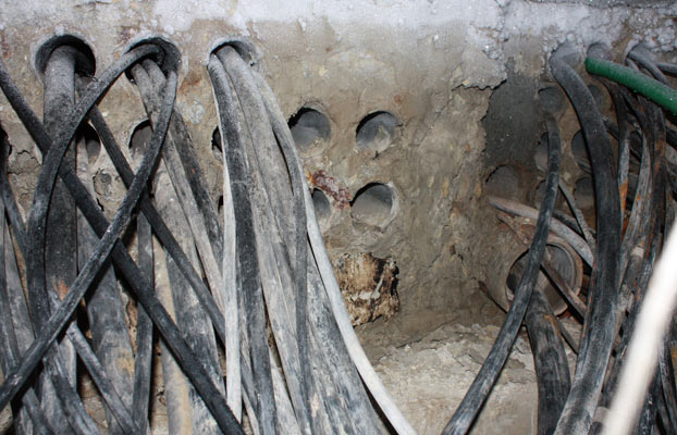
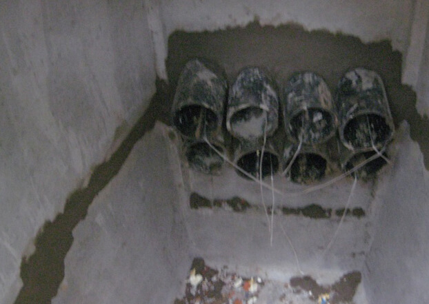
Communication cable wells
These structures, shown in the photo, are installed at intervals from 25 to 150 meters from one another. There are KKS (cable communication wells) made of bricks or reinforced concrete. Their size depends on the number of channels through them. Typically, standard prefabricated or reinforced concrete solid structures are installed.KKS happen standard or standard execution.
According to the design features, they are divided into:
- walk-throughs (also called straight lines) - they are installed on the ground where the cable duct device is implemented without turns or when the angle of deviation of the route from the center is not more than 30 degrees;
- corner;
- branching - they are placed in the places of supply or withdrawal of channels;
- station - they are located near the buildings where the cable equipment is located.
![]()
- for traffic areas - 80 tons;
- for pedestrian zones - 10 tons.
Preparation and marking of the route
Before the cable is laid in the cable duct, in accordance with project documentation carry out the marking of the laying of the route on the ground, determining the places for digging trenches and pits. On the working documentation underground utilities located in the area of the sewer network and crossing it with marks of approvals from the owners of these engineering systems should be marked.trenching
For earthworks, special equipment is usually used, and in places where communications pass close, pits or trenches are dug manually, and only in the presence of employees of organizations whose engineering networks are marked on the drawings.If the soil crumbles into trenches, their walls are reinforced with spacers or special shields.
The bottom of the ditches is arranged so that the pipes laid in a package are located with a slope in the direction of the wells, which should be approximately 3-4 millimeters per meter.
Pipe package laying
When there is a natural elevation difference on the ground, then the pipe package is placed at the same depth along the entire length between the viewing structures, but at a distance of ten meters from the revision devices, the laying is done with a slope. This is necessary to introduce pipes into the well at the desired height. Align the package relative to the horizon with a cord, which is pulled along the lateral border of the ditch.When laying the package, the pipes are placed along the trench, keeping a distance of 20-25 millimeters between them. This free space is covered with earth and rammed. The rows of channels in the package must be separated by layers of poured and then compacted soil with a thickness of at least 25 millimeters.
The ends of asbestos-cement pipes between devices are combined using heated polyethylene sleeves or cuffs fixed with a cement mortar. There is another way of docking when using a metal cuff and resin tapes.

If a flexible double-walled pipe for cable ducts is used, it is connected into a package by welding joints.
Cable inspection wells
Structural solution KKS assumes the presence of two branches - lower and upper. Straight wells from the ends have through holes for placing packages. Before installing the well in the right place, a pit is prepared.When the device is mounted, proceed to the placement of the hatch. Usually there are two covers in the kit: the upper one is made of cast iron, and the lower one is made of steel with shutoff valves for a padlock. From the inside, on the walls of the KKS, there are consoles, thanks to which the cable is laid in the sewer.
When arranging cable ducts with an open variant, crossings over the paths are performed by puncturing or using horizontal drilling. In the second case, a drill is used to equip the hole for the sewer network, which, in the process of returning, pulls the pipe into the finished space.
In some cases, in large settlements, tunnels and collectors are built underground specifically for laying engineering communications. Maintenance personnel have easy access. These facilities are equipped with ventilation systems and stationary lighting fixtures.
Cabling
For the arrangement of cable ducts, you can use different cables: electrical, copper, fiber optic, for communication. In one channel, the presence of cables that differ in their technological purpose and technical device is not allowed.For example, an electrical and communication cable should not be in the same channel so that they do not influence each other. When laying, intercity and main cables are considered priority, they are mounted in the lower holes of the pipe packages.
Laying begins after the preparation of sewer channels. First of all, professionals determine the cable channel for this. Next, the pipes are checked for the patency of the channel between adjacent wells. If it is workable, it is cleaned with a wire blank.
In the well, which limits the span, a meter long metal pins (cable sticks) are placed in the selected channel, which are joined together by means of a threaded connection. The employee performing the workpiece, pushing the first stick into the channel, connects the second stick to it and pushes the connection made. So he continues to do until the tip of the pin appears in another well of this span.
The cable service master, who receives the workpiece in the device, reports this to the observation structure from where the sticks were pushed. In the feeder, a wire is attached to the end of the last pin, which is reported to the receiving well. The worker in the last device removes the sticks until the last one emerges from the hole with a fixed wire.
When the cable sticks are removed from the pipe, the workpiece is considered ready, it is left in the channel, checked for passage. By using a workpiece with a trial cylinder attached to it and a metal brush (its diameter must correspond to the cross-sectional size of the channel pipe), they not only make sure that it is workable, but at the same time clean the hole from dirt and debris.
In practice, other methods of making blanks are also used, but the one described above is the simplest and most reliable.
Copper cable laying
Cables with a small capacity (such as distribution or intrazonal copper cables) with a quantity of no more than 100 pairs are usually tightened manually. At the same time, a so-called “stocking” made of galvanized steel is placed on the soldered end of the cable. A workpiece wire is attached to the sleeve or loop at the end.Cable laying is performed in the following sequence:
- The drum with the cable to be laid must be fixed on the side of the receiving device on fixtures (these can be goats, carts, etc.). It is served from the top of the drum.
- Split polyethylene sleeves or cable elbows are placed at the entrance to the hole in order to protect the cable coating from galling.
- Having received the appropriate signal from the performer of the work, in the receiving structure the workpiece is pulled out with the cable connected to it, and at the feeder they begin to adjust the tension of the cable coming from the drum. After completion of the installation in the span, the ends of the cable are checked for tightness and laid on the console. Its ends are marked with tags marked A or B.
- It is permissible to lay a cable in a sewer in winter in a polyethylene hose at a temperature of at least 10 degrees below zero, and in a lead sheath - at least minus 20.
Laying fiber optic cable
An optical cable is laid in the sewer in the same way as it is done with copper cable. True, there are a number of technological nuances associated with the peculiarity of the design solution of the optical fiber, as a result, it can be tightened with a segment of a kilometer long, and in sections that have turns, up to half a kilometer.Since the optical fiber is badly affected by mechanical loads from the outside, it is customary to protect it in the sewer with polyethylene tubes having a diameter of 25-63 millimeters. They are pulled into the channel and the cable is placed directly into them. At the same time, the gasket fiber optic cable in the sewer is always performed using a swivel and with an optical fiber gripping device that compensates for its stretching.
CABLE LINES AND THEIR FUNCTION
General information
Cable lines and communication networks
General information
Breakdown of the route, digging and preparing trenches for laying
cable
Laying the cable in a trench and protecting it from mechanical
damage
Laying in the sewer
CABLE INSTALLATION
Splicing of cable cores in couplings
Installation and soldering of lead sleeves
with aluminum shell by extrusion and explosion methods
MECHANIZATION OF CABLE WORKS
Tools and mechanisms used in construction and repair cable lines
Mechanization of works on digging trenches and on trenchless
penetrations
Comprehensive mechanization of work when laying cables
Soil, or electrochemical, corrosion
Intergranular corrosion
Measures to protect cables from corrosion
Protection of cables against corrosion by stray currents
Bibliography
CABLE LINES AND THEIR FUNCTION
General information
The modern development of communication devices, automation and telemechanics in railway transport is inextricably linked with the need wide application cable lines. The role of cable lines in transport has especially increased in connection with the introduction of single-phase electric traction. alternating current, since the replacement overhead line cable is the main means of protecting communication devices from dangerous and interfering electromagnetic influences created by traction currents.
Cable communication lines, together with air and radio relay communication lines and radio communications, form a single system designed to organize telephone and telegraph communications in railway transport. Cable lines are widely used in automation and telemechanics devices of railway transport for the transmission of telecontrol and distribution signals. electrical energy powering these devices.
Linear devices of modern cable lines consist of three main parts: cable, cable fittings and cable structures.
The cable is a collection of several conductors (veins) isolated from each other and from the ground and enclosed in a common protective sheath. Cable cores are used to transmit electrical energy. The main purpose of the protective sheath is to create a complete tightness that protects the cable from the penetration of moisture and moist air into it. In railway communication devices, automation and telemechanics, cables with aluminum protective sheaths and plastic sheaths (polyvinyl chloride or polyethylene) are used; Cables with a lead sheath, as well as with a rubber sheath, are used.
For some types of cables, for example, those laid in the ground or under water, to protect against mechanical damage and increase the strength of the cable, armor made of steel tapes or wires is applied over the sheath. The metal sheath of the cable and armor, which is also a metal screen, protect the cable cores and cable circuits from external electromagnetic influences created by various high current installations (electrified railways, high-voltage power lines, etc.).
Cable fittings are equipment with which the ends of the building lengths of the cable are connected, the device of cable branches and its terminations. Cable fittings include cable connectors and terminations, cable racks and boxes, boxes, junction boxes, group couplings, etc.
Cable accessories also include load coils and boxes, matching autotransformers designed to impart certain electrical properties to cable circuits, and equipment that ensures that the cable is kept under constant excess air pressure.
Cable structures are devices for the installation and installation of cable fittings, as well as devices and devices for laying and fastening cables. Cable structures include cable supports on which cable boxes are installed, as well as cable cabinets and booths. A complex type of cable structures is a cable duct designed for laying cables in large railway junctions.
Cable lines, depending on the method of laying the cable, are divided into underground, underwater and air. Due to the high reliability in operation, underground cable lines are most widely used in railway transport. Overhead lines are of limited use on the small cable networks of local telephone communications of railway stations. Underwater cable lines in railway transport are used only as inserts in underground cable lines, overhead communication lines and high-voltage signal lines of automatic blocking at the points where these lines cross water barriers.
Working conditions of cable lines
The working conditions of cable lines are more favorable than those of overhead lines. The operation of cable lines is not affected by such unfavorable phenomena for overhead lines as storms, ice, rain, fog, etc. Cable lines, to a lesser extent than air lines, are subject to dangerous and interfering electromagnetic influences created in communication, automation and telemechanics circuits various high-voltage power lines and contact networks electrical railways, as well as the effects of atmospheric overvoltages (lightning discharges).
Cable lines provide better continuity, high quality and reliability of communication devices, automation and telemechanics, are more durable and cheaper to operate, although their construction is more expensive than overhead lines. Damage on cable lines occurs much less frequently than on overhead lines.
There are, however, factors that can lead to disruption of cable lines or to a reduction in their service life. One of these factors is the destruction of the metal (lead, aluminum) sheath and steel armor of cables due to electrochemical (soil) corrosion or electrical corrosion. Electrochemical corrosion occurs due to the presence of organic and inorganic acids, alkali, nitrate salts, sodium chloride, etc. Soil with a high content of limestone, coal ash and slag also greatly affects the metal sheaths of cables and can render the cable unusable in a short time. Sheaths of cables laid near electrified railways direct current and tram lines using rails as a return conductor are exposed to the corrosive effects of currents wandering in the ground. This type of corrosion is called electrical corrosion.
When crossing rivers, cables are often laid over railway bridges. Under the influence of trains passing over the bridge, the bridge trusses vibrate, which is transmitted to the cables. Vibration of the cable adversely affects the condition of its metal sheath and can lead to cracks in it. Damage to the cable sheath due to vibration is called intergranular corrosion.
Underground cables can be damaged during various earthworks on the route (for example, during the construction of a water or gas pipeline) or as a result of soil landslides. Underwater cables laid along the bottom of rivers can be damaged by spring ice drift or ship anchors. To ensure the uninterrupted and reliable operation of cable lines and their safety, a number of measures are applied, which include: the creation of reliable cable designs that guarantee their sufficient mechanical strength and corrosion resistance; careful choice of route for laying cables; exact observance of the rules for laying and installation of cables, as well as taking the necessary measures to protect cables from corrosion. Great importance also has a systematic inspection of the cable route, periodic measurement of the electrical characteristics of cable circuits and compliance with the rules for the technical maintenance of cable lines and networks.
Classification of cable lines
Railway cable lines and networks are divided into communication lines and networks and lines and networks of automation and telemechanics.
Cable lines and communication networks
Cable lines and communication networks used in railway transport, according to the nature of use, can be divided into local and long-distance communication lines.
Cable local communication lines are laid on the territory of railway stations and junctions, as well as in cities where administrations and road departments are located. The combination of these cable lines in each of the listed points forms a cable network of local telephone communications. Local communication networks include switch communication and intra-station communication, as well as radio and clock networks.
Long-distance cable lines are used to organize telephone and telegraph wired connection between different remote points of the railway network. These lines carry out long-distance trunk communication between the Ministry of Railways and road departments, communication between road departments, as well as long-distance road communication between the road department and its departments, railway junctions and large stations.
Long-distance cable lines laid along the railway track are used to organize all types of departmental communications (train interstation, train dispatch, station, line-track, electric traction and distillation).
The organization of these types of communication requires the installation of a large number of branches from the long-distance cable to stations, sidings, track barracks, automatic blocking relay cabinets, etc. Therefore, they try to choose the route for laying long-distance cables in the railway right of way.
Lines and networks of automation and telemechanics
Lines and networks of automation and telemechanics, depending on the devices they serve, are divided into lines and networks of automatic blocking, electrical centralization, station blocking and hump centralization of mechanized sorting humps.
The cable network of automatic blocking is divided into station and distillation.
Auto-blocking cable lines also include cable inserts in high-voltage signal lines at the intersections of water barriers, in mountainous areas, on the territory of large stations, settlements, etc.
The station cable network of automatic blocking is a set of cable lines connecting signal centralizers located in the station attendant's room with relay booths or cabinets for input and output signals in both directions, etc. In addition, cable lines are laid from relay cabinets to battery wells, traffic lights, switch posts and cable racks of rail circuits.
The self-blocking cable network exists on the hauls at the location of the signal points and, as a rule, consists of cables laid from the cable box of the power tower of the high-voltage signal line to the relay cabinet and from the latter to the through traffic lights, battery well and cable racks of track circuits.
The cable network of the electrical interlocking of the relay system, which is accepted as the main type of interlocking, serves to connect the devices of floor devices (traffic lights, turnout drives, track circuits, etc.) with devices installed in relay boxes and the latter with a chipboard signaling point during centralization with local dependencies or with devices located in centralized posts (in case of centralization with central dependencies).
The cable network of hump interlocking is similar to the cable network of electrical interlocking. Recently, at marshalling yards, the widespread introduction of automation for the dissolution of trains on hills has begun. In this regard, at the marshalling yards, cables are laid that connect the floor-standing automation devices with the automation equipment installed at the hump posts.
The cable network of station blocking at stations with mechanical interlocking of switches and signals consists of cables connecting the control apparatus installed at the chipboard with executive devices installed in the premises of signalmen and switchmen, as well as cables connecting executive devices with rail pedals, coupling mechanisms and rubbing contacts for semaphore wings.
It should also be pointed out that in cases where a long-distance communication cable is laid along the roadbed, part of the cores of this cable is usually used for automation and telemechanics devices.
The cores of the communication cable are used for circuits of the electric wand system and semi-automatic track blocking, signaling circuits for automatic blocking, telecontrol circuits for traction substations on electrified sections of roads, as well as for dispatcher interlocking and control circuits.
DESIGN AND CONSTRUCTION OF CABLE LINES AND NETWORKS
General information
The design of cable lines and networks, as a rule, consists of the development of a technical construction project and working drawings.
Work on the technical project begins with familiarization with the terms of reference for the design and subsequent surveys and surveys of the area where the construction of cable lines and networks is expected. In the process of surveying, a choice of options for the route of lines or networks is made, the specific electrical resistance soils, outline the locations of amplifying stations, determine the conditions for the approach of the planned cable route with electrified railways and power lines, find ways to cross railways and highways, as well as water barriers, etc.
When designing long-distance cable lines in the technical project, the most economically and technically advantageous version of the cable route is outlined. The project chooses the type (brand) of the cable, its capacity, taking into account the prospects for the development of communication on the highway, the system and equipment for high-frequency sealing of cable circuits. On the basis of electrical calculations, amplifying and receiving points are placed on the cable line, measures are developed to protect the cable from the influence of electric railways, power lines, from soil corrosion and corrosion by stray currents, etc.
In the technical project of local telephone communications, the most advantageous location of the local telephone exchange and distribution cabinets, the capacity of the telephone exchange, the capacity and diameter of the cores of trunk and distribution cables are outlined, taking into account the future development of the local telephone network. In addition, it is indicated in which sections of the cable network it is necessary to build cable ducts, where underground armored cables should be laid or overhead cables should be suspended, and measures are outlined to protect cables from corrosion.
When designing cable networks for automation and telemechanics, for example, a cable network for electrical interlocking, the most advantageous route for laying a cable across the territory of the station is outlined, the choice of areas where it is better to lay group and individual cables.
Depending on the number of centralized arrows and signals, the capacitance of cables is calculated to turn on the arrows, power traffic lights and track circuits, as well as the capacitance of inter-office signal and power cables. Along with the choice of the type and capacity of cables, electrical calculations are made that determine the cross section of the power cores and the number of duplicated cores of signal cables, etc.
Each technical design of cable lines or networks must contain estimates for equipment, materials and labor, a work organization plan and the full cost of construction. Particular attention is paid to the issues of mechanization of work during cable laying.
Based on the approved technical design, working drawings are developed. The composition of the working drawings includes detailed drawings of the route of the cables to be laid. For laying cables outside settlements and railway stations, drawings are usually drawn in length on a scale of 1: 5000, and in width - 1: 2000. When laying cables on the territory of stations and settlements, drawings are drawn on a scale of 1: 1000 or 1: 500, and at cable crossings along artificial structures - on a scale from 1: 100 to 1: 500. The route of the cable being laid is applied to the drawings, indicating its distance from railway tracks, facades and other structures of passenger and track buildings, the contours of forests and green spaces, the route of lines communications, auto-blocking and high voltage lines.
The choice of route for laying the cable
The choice of the route of cable lines is one of the main design elements, since from right choice route depends on the cost of construction of cable lines and networks, their durability, as well as the reliability and uninterrupted operation. The route of underground cable lines is chosen based on the fact that the length of the cable laid between the given points is the smallest and the convenience of cable laying and its further maintenance and operation is ensured. On hauls of railways, the cable route, as a rule, passes in the right of way.
The cable route, if possible, is chosen on that side of the railway tracks, where the majority of linear and other points are located, in which branches are arranged. The route is planned in such a way that the number of cable transitions through various kinds of obstacles (crossing railway and tram tracks, ravines, highways, etc.) is minimal. If it is necessary to cross the railway bed for the transition, you should choose a place with the least number of tracks; laying cables under turnouts and joints is not allowed.
When choosing a route, you should avoid laying a cable in soil with a high content of lime, in heavily swampy and marshy places, in places where alkalis and acids accumulate (near chemical and metallurgical plants, slaughterhouses and sewers), as well as in places with slag heaps and clogged construction sites. garbage with the presence of lime and cement, since in these conditions the cable is highly exposed to soil corrosion.
In populated areas, the cable route should, if possible, pass through streets that are least loaded with other underground structures (water supply, sewerage, gas pipeline, power cables etc.), as well as to have the greatest distance from the tram tracks. In addition, they tend to lay the route away from large plants, factories, power plants, depots, etc.
The laying of underground armored cable, as well as the installation of cable ducts in settlements, should be carried out under the pedestrian part of the streets in order to less disturb traffic during the laying of the cable line and its operation, while the distance from the red line of houses in cities and towns should not be less than 1.5 m, and from the foundations of houses on country roads - at least 5 m.
The minimum distance of the communication cable from the track of electric railways of alternating current and high-voltage power lines is determined on the basis of the electrical calculation of dangerous and interfering influences created by these devices in cable communication circuits. Ordinary communication cables are laid no closer than 5 m from the edge of the sole of the railway embankment. In some cases (within the station, in heavily swamped and cramped areas, etc.), communication cables can be laid in the immediate vicinity of the railway track, however, the distance between the cable and the axis of the extreme track must be at least 2.5 m.
If the cable is laid along highways, then the distance from the cable to the edge of the embankment is recommended to be taken equal to 5 m. The distance from the cable to forest plantations should be at least 3 m, and from individual trees - 2 m. Communication cables should be laid from water supply and sewerage no closer than 0.5 m, from the oil and gas pipeline - 1 m, hot pipeline - 2 m. These distances can be reduced to 0.25 m, provided that the cable is laid in an asbestos-cement pipe.
The route of signal and power cables of automation and telemechanics can pass within the station both on the side of the railway track and between the tracks. In this case, the distance between the nearest rail and the cable must be at least 1.6 m. If it is impossible to maintain these distances according to local conditions, then it is allowed to lay the cable at a distance of 1 m from the nearest rail, provided that the cable is equipped with an insulating sewer. Signal cables can be laid without restriction in the same trench as power cables with an operating voltage of up to 500 V.
Power cables with voltages above 500 V are laid in a separate trench or in a common trench with signal cables, but at the same time the power cable is laid to a depth of 1.5 m and covered with brick or concrete slabs from above, and the signal cable is above it at a distance of 0.45 m with a shift to the side by 0.15 m. The distance between power cables and communication cables must be at least 0.5 m.
When crossing railway or tram tracks, the depth of laying cables for communication, automation and telemechanics must be at least 1 m from the rail foot, and with a highway or motorways, at least 1 m from the roadway. In this case, the cables at the intersection are laid in asbestos-cement pipes Oh. At the intersection of communication cables with power cables, the distance between them at the intersection should be at least 0.25 m if the communication cable is laid in an asbestos-cement pipe, and 0.5 m in its absence.
Signal cables, when crossing them with power cables and other underground structures, should also be laid at a distance of 0.5 m from these structures; if this distance cannot be maintained according to local conditions, then it is allowed to reduce it to 0.3 m. At the same time, at the intersection of the signal cable with power cables, it must be laid in an asbestos-cement pipe. The distance between signal cables crossing each other must be at least 0.1 m.
When choosing a submarine cable route at the intersections of water barriers, places are chosen where the water barrier has the smallest width, a flat bottom and sloping banks. The cable must not be laid in places where ships are anchored in winter, in the area where rafts are anchored, in places where watering and bathing livestock are observed, as well as where ice jams are observed or the river changes its course.
At railway and highway bridges across floating and navigable rivers and reservoirs, cable laying is allowed at a distance not closer than 300 m below the bridge along the river, and from bridges across small non-navigable rivers and ravines - not closer than 30-50 m.
Breakdown of the route, digging and preparing trenches for cable laying
The breakdown of the route of the underground cable line is carried out in accordance with the working drawings using milestones and pegs in the same way as the breakdown of the route of the overhead line. Pegs are hammered along the axis of the future cable trench on straight sections of the route after 5-10 m or more, as well as at the places where the trench turns.
As a rule, cable laying is carried out mechanized using cable layers. In this case, preliminary digging of the trench is not carried out, since the cable layer performs this work simultaneously with the laying of the cable.
In cities and towns, at railway stations, trenchers are usually used for digging trenches, and where their use is difficult (when crossing railway tracks, between tracks, on the slopes of embankments, etc.), the trench is dug manually. When digging a trench by hand, it is dug so that the side walls of the trench have some slope. This makes it easier to dig a trench and prevents the walls from crumbling. Trenches up to 1 m deep in non-caving soils can be dug without slopes.
The depth of laying communication cables in soils of categories I-III should be at least 0.9 m, and in rocky soils - at least 0.5 m in the absence of an alluvial soil layer and 0.7 m in its presence. In settlements and on the territory of large stations, the depth of the cable trench is increased to 1.0-1.2 m. The width of the trench when laying one or two cables is taken equal to 0.3 to 0.4 m along the bottom and, accordingly, 0.4 .5 m along the top of the trench. The depth of laying signal cables in the station between tracks and on the side of the tracks outside settlements is 0.8 m, in cities and towns at intersections with railway tracks and highways - at least 1 m.
Cable trenches at the turns of the route are dug in such a way that the minimum bending radius of the cable being laid with a lead sheath is at least 15 times, and for cables with an aluminum sheath - at least 30 times the outer diameter of the cable; when laying cables with a plastic sheath, their bending radius must be at least 10 times the outer diameter of the cable. On the slopes of ravines (on the ascents and descents), a trench is dug in a zigzag manner with a deviation of the bends from a straight line in one direction and the other by 1.5 m, and the length of the bends is taken on the order of 5 m.
In places of future installation of connecting and branching couplings and pupino boxes, the trench is expanded, tearing off the foundation pit for the convenience of subsequent installation work. The depth of the pit is made 10 cm deeper than the bottom of the trench.
The bottom of the trench is leveled and cleaned of stones and rubble, and before rolling out and laying the cable in stony and rocky soils, it is covered with a layer of sand or loosened soil up to 10 cm thick. This layer is called the “lower bed”. In soft soils, beds can not be made.
Transporting the cable and preparing it for laying
The preparation of the cable for laying begins with the transportation of drums with cable along the route in cars or special carts. If the route passes in close proximity to the railway track, the cable is transported on railway platforms. When loading drums, as well as when rolling them on the ground, it is necessary to ensure that the direction of rotation of the drum coincides with the direction of the arrow on the cheek of the drum.
Before transporting the cable along the route and before laying, check its condition. The check begins with an external inspection of the cable drums, checking the integrity of the sheathing, the bolts fastening the drum, and the termination of the cable ends. In addition, the cable is checked for tightness.sheaths. Usually, all long-distance and local communication cables in metal (aluminum, lead) sheaths come from the manufacturer with air pumped under the sheath under pressure exceeding atmospheric pressure by 4.9-104-9.8-104 Pa. (about 0.5-1.0 kg / cm2), and a valve soldered into one end of the cable. The integrity of the sheath, cables is checked according to the pressure gauge attached to the valve. If there is excess pressure remaining in the cable, the sheath integrity test is completed.
If it turns out that there is no excess pressure in the cable, then air is pumped into the cable with the help of a pump, compressor or using a cylinder with compressed air and a reducer to a pressure of 9.8-104 Pa. When atmospheric air is pumped into the cable, it is preliminarily dried (moisture is removed) by passing through a chamber with moisture-absorbing calcium chloride or silica gel (silicon dioxide). If, after pumping, the pressure established in the cable does not decrease within 24 hours, this indicates the integrity of the sheath; otherwise, find and repair damage to the shell (crack, puncture, etc.). After repairing the damage to the sheath of long-distance cables, measure the insulation resistance of the cores and working capacity cable chains, and for local communication cables, the insulation resistance is measured and the cores are checked for breakage and their communication with each other and with the metal sheath.
The measurement of insulation resistance of cores, the working capacitance of cable circuits and other electrical measurements are carried out by cable devices and bridges of various kinds. The technique of these measurements is described in the course "Electrical measurements".
To check the cores for a break and for their communication with each other and with a metal sheath, both ends of the cable on the drum are released over a length of 80-300 mm from protective coatings and a metal sheath. Then, insulation is removed from all the cores of one end of the cable over a length of 1.5-3 cm, the stripped cores are connected to each other and to the lead sheath (Fig. 157) using copper wire. The cores of the second end of the cable are cut into the so-called pyramid, which is obtained as a result of the fact that the cores of each subsequent layer are cut 15-20 mm shorter than the previous one.
When checking the cores for communication between themselves and with the cable sheath, one pole of the battery with a voltage of 3.0-4.5 V is connected to the cable sheath (Fig. 1, a), and on the other - through telephone 3 in series with each of the cable cores, previously disconnecting it for the duration of the test from the common beam. If the tested core has a connection with any other core or with a metal sheath, then a click is heard in the phone under the action of the battery current according to the scheme: battery pole, cable sheath 2, tested core, telephone and another battery pole.
To test the wires for a break, all the wires are attached to the sheath and the test is carried out from the side of the pyramid. When you touch the test core of the free end of the wire coming from the telephone, a click should again be heard in the latter. If the click does not appear on the phone, then the tested core is broken.
When testing the wires for breakage and communication, it should be borne in mind that with a long cable length, a click in the telephone (weaker) can be obtained due to a noticeable electrical capacitance between the wires and between the wires and the sheath. Therefore, with a long cable length, it is advisable to replace the phone with some other device (ammeter, voltmeter).
Signal cables with a lead sheath and all types of signal and communication cables with non-metallic sheaths are not put under excessive pressure and their condition is checked only by electrical measurements insulation resistance, lack of communication between the cores and their breakage, as well as external inspection of the cable when rolling it from the drum. In this case, the measurement of the insulation resistance of the cores and their test for a break in signal and control cables is carried out using a megohmmeter.
The cutting of the cable for measurements using a megohmmeter is carried out in the same way as when measuring the connection between the cores and the breakage of the cores. When measuring the insulation of a core, one conductor connected to the terminal of the Lmegohmmeter is connected to the core being tested, and the other conductor is connected to terminal 3 with a metal sheath or with the rest of the cores connected to each other (for cables with a plastic sheath). By rotating the handle of the megohmmeter with a frequency of about 130 rpm, the value of the insulation resistance of the core is counted on its scale. Depending on the type of megohmmeter, they can measure the value of insulation resistance up to 500-1000 MΩ. When testing with a megohmmeter, the core was broken, if the core being tested does not have a break, then when the handle of the megger is rotated, the arrow of its device will remain at zero. In the event of a break, the arrow will deviate to the left, indicating the amount of high resistance, which will indicate the presence of a broken core.
At the end of the electrical tests, the cable cores are cut off and the metal sheath of both ends of the cable is sealed on the drum; the ends of cables with a non-metallic sheath are carefully insulated with PVC tape or in another way to prevent moisture from entering the cable. Long-distance communication cables and local communication cables with a metal sheath with a capacity of 50 pairs or more are put under excess pressure before laying.
Laying the cable in a trench and protecting it from mechanical damage
The unwinding of the cable from the drums and its subsequent laying in the trench is carried out mechanically or manually.
If local conditions do not allow the use of a mechanized cable laying method, then the cable is unwound and laid manually. To do this, the cable drum is installed near the trench on metal or wooden goats so that the drum can rotate freely on an axis inserted into its sleeve. The drum is installed so that its rotation on the axis occurs in the direction of the arrow shown on the cheek of the drum, and the cable, when unwinding, goes on top of the drum.
After installing the drum, the boards covering the cable are embroidered and unwinding of the cable begins, and the drum is rotated by the cheeks, and not by the cable traction force. The workers carry the cable to be unwound on their hands and first lay it along the edge of the trench, and then lower it to the bottom. The number of workers involved in unwinding and laying the cable is taken from such a calculation that the mass of the cable per worker does not exceed 35 kg. The cable lowered into the trench is laid with some slack along a slightly wavy line without tension to prevent excessive cable tension in the future during shrinkage and possible soil displacements.
If there are a large number of intersections of the cable route with various underground structures, when the cable cannot be lowered into the trench, it is dragged along the bottom of the trench along the rollers using a steel cable and a hand winch, tractor or tractor.
"The laying of the construction lengths of the cable is carried out in such a way that in the pits, where connecting or branching couplings are subsequently installed on the cable, the ends of the cable overlap each other by about 2 m. With a two-cable system, both cables are laid into the trench simultaneously.
After laying the construction lengths of the cable, their condition is re-checked (sheath tightness test, electrical measurements) in order to find out if the cable was damaged during installation, and then they start backfilling the trench.
In soft soils, backfilling is carried out with soil removed from the trench, and in stony and rocky soils, the cable is first covered with a layer of sand or soft soil 10 cm thick, forming an “upper bed”. Backfilling and compacting the soil in the trench is carried out in several stages. First, a layer of soil 0.2-0.3 m thick is poured and it is compacted tightly. Then the next layer of soil of the same thickness is poured and also tamped, etc. In settlements and on the territory of stations, backfilling and tamping of the trench are carried out with simultaneous watering of the soil layers with water, which reduces its further settlement.
The pits in which, during the installation of the cable, connecting, branching couplings and pupin boxes will be installed, when backfilling the trench, leave open and fall asleep only after the completion of the installation work.
The protection of the cable being laid from mechanical damage is carried out when it is laid under railway and tram tracks at the intersection with highways and dirt roads, under the carriageways of streets, at intersections with underground structures and other cables, enclosing the cable at the intersection in asbestos-cement pipes in such a way that so that they go 1 m beyond the intersection.
Cables are protected when they are laid in rocky soils at a depth of 0.5 m, in orchards and orchards, when ten or more signal and other cables are laid in one trench, as well as when power cables with an operating voltage higher than 1 kV. In these cases, the cable is covered with concrete slabs or a layer of red brick for protection.
After laying the cable, an executive plan for the route of its laying is drawn up. At the same time, the distance of the cable from any landmarks is accurately measured (for example, from the axis of railway tracks, picket and kilometer posts, buildings in settlements, etc.). The route of long-distance cables is also marked by installing measuring posts (pickets), marking with them the installation sites of connecting and branching couplings, cable turns, etc. Reinforced concrete measuring posts are installed at a distance of 1.5 m from the cable or coupling towards the field, burying them into the ground to a depth of 0.7 m. Each column is supplied with a plate on which the purpose of the column is conditionally indicated, for example, a coupling, a pupin box, turning the cable to the right, etc.
In addition to the route of the laid cable, other underground and above-ground structures are applied to the plan, for example, water and gas pipelines crossing the cable and running parallel, other cables, roads, ditches, etc., located in a strip of 20-30 m from the cable.
Drawing up an executive plan facilitates the further operation of the cable and allows you to more accurately and quickly determine the location of its damage.
Methods and features of laying communication cables
Laying in the sewer
The depth of the trench for laying cable sewer pipelines is chosen such that the distance between the upper part of the pipeline and the soil surface under the sidewalk is at least 0.5 m, under the pavement - at least 0.7 m. The width of the trench depends on the total capacity of the sewer pipeline.
Before laying pipes, the bottom of the trench is leveled and well rammed, and a bed of sand or sifted earth is made in rocky soil. Pipes are laid in a trench with a certain slope (3-4 mm per 1 linear meter of pipeline) towards cable wells to drain water that can enter the pipeline.
Asbestos-cement pipes laid in a trench are joined end-to-end using asbestos-cement couplings with an inner diameter slightly larger than the outer diameter of the pipe. Rubber rings are installed between the pipe and the coupling to create tightness or gaps are sealed with resin tow, after which the junction is sealed with cement mortar or filled with bituminous mastic.
A more widespread method of connecting pipes with the help of cuffs made of roofing steel, tightened on. joints with subsequent sealing with cement mortar. Under the cuff, before tightening it, a bandage made of hydroisol or fabric (burlap, calico) impregnated with bituminous mastic is laid.
The connection of asbestos-cement pipes with the help of polyethylene cuffs in the form of a cylindrical pipe 90 mm long is also used. The inner diameter of the cuff is 5 mm less than the outer diameter of the pipes to be connected, and the cuffs are put on the joint, preheating them in water to 80-90 °, as a result of which their diameter increases and they soften. The heated cuff is first put on one end of the pipe to the protrusion in the middle of the cuff, and then on the other side to the end of the second pipe to the protrusion. After the cuff cools, it narrows and fits snugly around the junction of the pipes. Polyethylene pipes are joined together end-to-end by welding. When laying a multi-hole sewer, a block of several pipes is arranged, sealing the joints into a common concrete belt. At the installation sites of the wells, a pit is torn off, into which the parts of a prefabricated reinforced concrete well are lowered with a crane or a winch, then connecting them with cement mortar. Pipelines lead into the holes provided in the side walls of the well, and are also sealed with cement mortar. A round cast-iron manhole with two covers is placed on top of the well inlet, and steel brackets with consoles for laying cables are placed inside the well on its walls.
Before pulling the cable in the sewer, they first check the condition of its channels. To do this, a steel cable is pulled from one well to another with the help of screwed duralumin sticks, and then a trial cylinder and a steel brush are pulled with a cable to align and smooth the walls of the channels at the junction of the pipes and clean the cavity of the pipes from litter.
The cable is pulled through the sewers along the sections between adjacent wells, for which a drum with a cable is installed on the goats above one of the wells, and a manual or motor winch is installed at the adjacent well, then the cable, stretching through the pipeline channel and passing it through the block, is fastened to the end of the cable using a steel cable stocking and, turning the handle of the winch, pull the cable through the channel. In order to prevent the cable from being damaged by the edges of the pipeline, a cable elbow or bushing is installed at the inlet and outlet of the pipeline. To reduce traction, the surface of the lead sheath of the cable is lubricated with technical petroleum jelly when it is pulled. Cables in a plastic sheath cannot be lubricated with petroleum jelly, and the sheath of such cables is moistened with water when pulled. Before and after pulling the cable, it is tested. In the wells, a reserve of cable is left, which is necessary for the installation of connecting and branching couplings and for laying the cable along the walls of the well.
CABLE INSTALLATION
Cutting the ends of communication cables with metal sheaths
The scope of work during the installation of cables depends on the type of cable, the method of laying it and the purpose of the cable line.
The main types of installation work include splicing individual pieces (building lengths) of the cable in connecting and branching couplings, installation of cable terminal devices (terminal couplings, boxes, etc.). and on cables contained under excessive air pressure, the installation of gas-tight couplings. High quality and thoroughness of installation work, strict observance of the rules and instructions for installation, as well as cleanliness and accuracy during cable installation largely determine the reliability and uninterrupted operation of the cable line in operation.
The cutting of the ends and splicing of the cable laid directly in the ground is carried out in pits, and the cable laid in the sewer - in cable wells. At the same time, the work on splicing the ends of the cables should be preceded by testing and electrical measurements of the spliced cables.
Then the ends of the cables are marked in such a way that the cable, after installing the coupling on it, can be laid on the consoles in the cable well or lay out the cable reserve in the pit in case the coupling is rebuilt during the operation of the cable. The well or pit is cleared of crumbling earth and debris, and a tent is set up over the pit, regardless of the weather. The ends of the spliced cables are laid on the goats and firmly tied to them.
The cutting of the ends of bare lead-lined cables of the brands TG, TZG, etc. is carried out as follows. The ends of the cables are cut with a hacksaw so that they overlap each other by a length equal to or slightly greater than the length of the installed lead sleeve, and on the lead sheath Mark the future position of the edges of the sleeve during its subsequent soldering. If a cylindrical lead sleeve without a cut is used when connecting the ends of the cables, then it is put on with a cone forward on one of the ends of the cable and temporarily moved along the cable to the side so that it does not interfere with further cutting; when using a coupling with a cross section, one of its halves is put on one and the other on the other end of the cable. Departing from the marks on the cable by 30-40 mm, circular cuts are made on the cable sheath and from them to the ends of the cables two longitudinal cuts are made with a distance of 6-8 mm between them. These cuts must be made carefully enough so as not to damage the belt insulation of the cable located under the lead sheath. The narrow strip of lead formed as a result of the incisions is grasped with pliers and torn off. After that, the rest of the lead sheath is captured, unbent and also removed.
The lead sheath at the edge is slightly bent outward, the burrs are removed and the bare cable twist is tied with a collar from a calico tape boiled in paraffin so that part of it gets under the lead sheath, which protects the belt insulation of the cable sheath from damage on the sharp edge of the lead sheath and from breaking the belt insulation with subsequent bending to the sides of cable pairs or fours. Further, paper tapes of belt insulation are wound from the cable twist and, having rolled them into rollers, they are temporarily tied to the cable.
For local communication cables of the TG or TB brand with air-paper insulation, the cable twist freed from belt insulation is usually scalded with the MKP-1 cable mass. To do this, the ends of the cables are placed over a baking sheet and watered with a cable mass heated to 120-130 ° C until foam and air bubbles stop emitting from the cable twist. Cables with cord-paper and plastic insulation are not scalded.
The ends of underground armored cables TB, TZB, etc., when installing connecting and branching couplings, are usually cut in pits. The ends fixed in the pit on the goats
armored cables are cut so that they overlap each other by a length equal to or slightly greater than the length of the cast iron sleeve.
Against the cylindrical parts of the coupling, bandages of three to four turns of solder wire are installed on the outer cover of cable yarn; the same wire bandages are placed on the tape armor at the edge of the cables, so that when the outer cover is removed, the armor tapes do not unwind. At bandages, the cable yarn is cut and removed. At a length of 40-50 mm from the cut of the cable yarn, the surface of the armor tapes is carefully cleaned with a file and tinned. At a tinned place at a distance of 15 mm from the cut of the cable yarn, bandages are installed from two pieces of copper wire with a diameter of 1.2 mm and a length of about 750 mm and soldered to the armor, and the remaining ends of the wire are twisted and temporarily bent to the side. These ends of the wire further serve for the electrical connection of the armor and the lead sheath of the spliced ends of the cables.
At a distance of 10 mm from the edge of the bandage, the armor tapes are alternately filed to half the thickness with a triangular file, then, having removed the bandages and unrolled the armored bands, they are broken off along the file. After removing the armor, the bottom layer of cable yarn and cable paper is unwound and carefully cut off, and the exposed lead sheath is rubbed to a shine with a rag soaked in gasoline. Further cutting of the ends of an armored lead-sheathed cable is carried out in the same way as cutting bare lead-lined cables.
The cutting of cables with an aluminum sheath has some features compared to the cutting of cables with a lead sheath. After marking on the aluminum sheath the places for the future installation of the cones of the lead coupling in the places of the future cut of the sheath, ring cuts are made on it with a trihedral file, and from these cuts away from the ends of the cable, the aluminum sheath is tinned with zinc-tin solder.
Before tinning, the shell at the place where the solder is applied is wiped with a rag soaked in gasoline, and thoroughly cleaned with a steel carded brush. Tinning is carried out using tinning tongs, the main part of which is a soldering detachable sleeve made of copper. The inner diameter of the sleeve must be equal to the outer diameter of the tinned shell. A trough-shaped recess is cut inside one half of the coupling, in which a steel plate (cutter) is fixed.
The clutch of the tin tongs is heated with a blowtorch flame to the melting temperature of zinc-tin solder, and solder is deposited on the inner surface of the clutch, which accumulates in the trough-shaped cutout of the clutch; then, quickly spreading the tongs, wrap the sleeve around the aluminum sheath and, squeezing the handles of the tongs, turn them around the cable axis two or three times and remove them; when the tongs are turned, the cutter removes the oxide film from the surface of the shell, and therefore the surface tinning proceeds quite well. In the absence of tinning tongs, tinning is performed by heating the place of tinning with a blowtorch flame and rubbing the molten solder over the surface of the shell with a steel carded brush that removes the oxide film.
A layer of conventional lead-tin solder POS-30 is applied to the tinned belt of the sheath and smoothed with a rag soaked in scalded cable mass. After such tinning of the aluminum sheath of the cut ends of the cables, the sheath is broken along the annular notch made earlier and, rotating in the direction of winding the belt insulation tapes, is removed. Further cutting is carried out similarly to cutting the ends of lead-sheathed cables.
Splicing of cable cores in couplings
Before proceeding with the splicing (connection) of the cores, all foreign objects (cuttings of cable yarn, armor, etc.) are removed from the pit or well, and a tarpaulin is spread on the bottom of the pit or well. Then the tool for connecting the wires is prepared and wiped with gasoline, and the fitter performing the splicing thoroughly wipes his hands with gasoline. Mounting materials are dried immediately before splicing the cores, and the paper sleeves, group rings and threads used for splicing are scalded.
Splicing begins with the disassembly of the cable layers. To do this, the upper and then subsequent layers of the cable are divided into two bundles, which are then bent and temporarily tied to the sheath. Starting the splicing of cores in cables with paired twist, usually pairs of cores of the lower half of the outer layer are spliced, and then pairs of cores of the lower half of the next layer, etc. Then all the cores of the central layer are spliced and then all the cores of the upper half-layers are spliced in the order they follow from the central layer to the outside. When connecting the ends of corded cables with a quad twist of the cores, the cores of the quads of the central layer are first spliced, and then the subsequent layers. In all cases, initially in each lay, the wires of a counting pair or a counting (control) quadruple are first spliced, and then subsequent pairs or quadruples.
Consider the technology of splicing cores in the four. This operation begins with the fact that two fours of the same serial number in the spliced ends of the cable are aligned and laid side by side. The threads wound on these quadruples are shifted to the lead sheath and tightened, then group rings are put on both quadruples and the number of the quadruple is written on them, and insulating sleeves are put on each of the cores of the quadruple of one of the ends of the cable.
When mounting couplings without balancing the cable chains, in each of the fours, cores of the same color are spliced with each other. In those couplings where circuit balancing is provided, the connection of the cores to each other is carried out according to a special rule. Having selected two cores in the fours, which should be connected to each other if the insulation is tubular or paper cord, the solder twists them two turns together with the insulation, and then, removing the insulation from the cores below the twist and folding the bare cores, also twists them and cut off at a distance of about 30 mm from the beginning of the twist. The remaining cores of the four are twisted in the same way. For cables with plastic insulation, the cores are not twisted together with the insulation, but the cores are twisted after the insulation is removed from them.
Prepared strands of cores are moistened with a rosin solution over a length of 15-20 mm and sealed with POS-40 solder. When sealing, it is convenient to use a soldering iron in the form of a cup with molten solder. The sealed twist of the core in the quarter is bent to the side opposite to the put on sleeve, and then the sleeve is put on the twist. The cores isolated in this way are folded together on both sides and the group rings are pushed forward.
The twists of the cores of different fours are arranged along the length of the coupling so that they are distributed evenly along the entire length of the coupling, which makes it more compact. At the end of splicing of all cable cores, the splice site is thoroughly dried to remove moisture from it, which is especially important for cables with paper core insulation. For cables that were scalded when cutting the ends, drying is carried out by secondary scalding. Other cables with paper or paper cord insulation are dried with a blowtorch flame. To do this, the lamp is installed so that its flame passes under the splice and hot air covers the entire twist.
After drying, the splice is packed with several layers of cable paper tape; for cables with plastic insulation, the splice is first wrapped with polyethylene tape, and then with several layers of cable paper tape.
When laying and installing long-distance cables in some couplings; called capacitor circuits, they perform balancing of cable circuits by connecting balancing capacitors between the cores, as well as between the cores and the ground. If the capacitor must be connected between the conductors in a quarter, then its conductors are soldered to the corresponding conductors. When a capacitor is connected between any core and ground (cable sheath), one of its conductors is soldered to the core, and the second to the conductor connecting the metal sheaths of both ends of the cable. After the connection of all capacitors is completed, the cable twist is dried and wrapped in cable paper, the capacitors are laid around the circumference of the splice and tightly fixed with a harsh thread.
Installation and soldering of lead sleeves
Before installation on the cable, the coupling is thoroughly wiped and dried, and in those places where the coupling is soldered to the lead sheath, as well as in the places of cuts, it is cleaned to a metallic sheen and sometimes tinned to facilitate soldering.
If a cylindrical sleeve without a cut is to be sealed, then after stripping the cable sheath to a shine in the places of its soldering with the cones of the sleeve, the sleeve is shifted from the cable to the place of the splice, the cone present on the sleeve is carefully adjusted with a wooden hammer until the edge of the cone fits tightly to the cable sheath; at the other end of the coupling, where the cone is missing, it is made with a wooden hammer using mandrels. If a coupling with one transverse cut is installed, then it is moved apart before installation, and then, having installed it on a splice, it is compressed so that the edges of the longitudinal seam are on top of each other, and also set with a wooden hammer. Couplings with one or two longitudinal cuts are temporarily fastened with a wire clamp before sealing.
After that, a solder stick of the POS-30 brand is heated in the flame of a blowtorch, and when it reaches the melting temperature, a layer of solder is applied to the place of soldering. Then the blowtorch flame is transferred to the place of soldering, and, heating the superimposed layer of solder, it is kneaded and smoothed with a rag soaked in stearin until the soldering takes the required shape. The soldered sleeve is cooled with stearin and inspected in detail, checking that the soldering has a smooth surface without cracks and melted places (shells).
The sealing quality of the coupling is also checked with compressed air. For this purpose, a valve is soldered into the clutch body, to which a pump or compressed air cylinder is attached, pressure is created in the clutch in the range of 9.8-104 Pa, while the clutch and all places are moistened with soapy water and in the absence of air bubbles coming out of the clutch , judge the good quality of its sealing. After checking the tightness of the coupling, the valve is unsoldered, and the hole formed in the coupling is sealed.
The technology for sealing lead sleeves on cables with an aluminum sheath (for example, MKBAB, MCPAB, etc.) has a number of features. So, when sealing the coupling cones, the scalding mass MKS-1 should be used as a flux instead of stearin. In order not to damage the plastic tapes or hoses that protect the aluminum shell and armor, the coupling must be soldered as quickly as possible, preventing it from overheating; for the same purpose, the aluminum shell near the place of sealing of the coupling is cooled with a wet rag or coolers are installed on the shell - massive detachable copper disks.
To increase the tightness and reliability of sealing the lead sleeve on the main railway cables, the bare part of the aluminum sheath of the cable and the lead sleeve are covered with MBR bitumen-rubber mastic with a layer of 0.5-0.8 mm, over which a layer of polyethylene tape is wound with overlapping. Alternate coating with mastic and wrapping with tape is repeated three to four times. At the same time, the bare armor of the cables is also covered with the second and subsequent layers of tape and mastic. On the top layer of mastic after its thickening, glass tape pre-impregnated with mastic is wound with overlapping.
Such a multi-layer coating not only increases the tightness of the coupling, but also aims to protect the aluminum shell and armor from soil corrosion and corrosion by stray currents in the places where the couplings are installed.
The concept of connecting the ends of cables
with aluminum shell by pressing and explosion methods
The connection of the ends of cables with an aluminum sheath by cold pressing (cold welding) and explosion is used for a wide range of cable laying works, as a rule, performed by specialized organizations. These methods are designed for specially trained teams equipped with special equipment and tools. Therefore, below are only general concepts about the technology of performing these works.
When connecting the ends of the cable by cold pressing, after cutting the ends of the cable (without tinning the aluminum sheath), with a special device, the aluminum sheath of both ends of the cable is expanded (expanded) over a length of 35-40 mm and steel support bushings are inserted between the cable core and the sheath. These bushings protect the cable core from crushing during further crimping.
Then, an aluminum sleeve is put on one of the ends of the cable, and on the other (if it has an external polyethylene hose - a polyethylene tube designed for subsequent protection of the aluminum sleeve-tube. with a brush, the inner surface of the coupling tube and the flared sections of the cable ends are lubricated with BF glue or quartz-vaseline paste (a mixture of petroleum jelly with fine sand).
For cables with an external polyethylene hose, the ends of the pressed sleeve are wound with polyethylene tape, the polyethylene sleeve is pulled over the splice of the cable and the joints of the polyethylene sheath with the cable hose are wrapped with three layers of polyethylene tape, on top of which glass tape is applied and the joints of the polyethylene sleeve with the cable hose are heated with a flame blowtorch until the glass tape darkens. After cooling, the glass tape is removed and the installation of the coupling is completed.
If the cable does not have an outer polyethylene hose, then to protect the aluminum sheath of the cable and the coupling tube, they are covered with bitumen-rubber mastic and wrapped with polyethylene tape in the same way as when sealing a lead coupling on the cable. The connection of the ends of the aluminum shell by the cold welding method differs from the cold pressing method only by a slightly modified design of the support bushings and dies.
If in the future it is supposed to connect the aluminum tube-coupling to the cable armor for grounding the coupling, before pressing, then tinned copper plates 0.3X10 mm 100 mm long are laid under the tube-coupling from both ends.
The connection of the ends of cables with an aluminum sheath by the explosion method differs from the cold pressing method mainly in that instead of a press, explosive charges are used, installed on the ends of an aluminum sleeve tube. When they explode, the blast wave tightly connects the tube-coupling. with flared ends of the aluminum sheath of the cable.
In addition to the described methods for connecting the ends of cables with an aluminum sheath, the gluing method using VK-9 glue has become widespread. This method uses two, one inside the other, aluminum half-couplings with necks corresponding to the outer diameter of the aluminum sheath of the cables.
After cutting the ends of the cables, one half-coupling is pushed onto one end of the cable, and the other - onto the sheath of its other end. When the splicing of the cable cores is completed, the half-couplings are shifted onto the splice, having previously applied a layer of VK-9 glue to the surface of the half-coupling of a smaller diameter included in the other half-coupling and to the ends of the cable sheath at the location of the mouths of the half-couplings. In this case, if necessary, for a tight fit of the coupling halves to each other and the necks to the shell, a gauze bandage impregnated with glue is wound up at the place of their joints.
Then, a layer of VK-9 glue is applied to the mounted sleeve and the ends of the cable sheath emerging from it over a length of 30-40 mm and wrapped with a gauze bandage. In total, 5-6 layers of bandage are wound in this way with smearing with glue. After that, an iron casing is temporarily installed on the mounted coupling and heated with a blowtorch flame so that the temperature inside the casing does not exceed 60-80 ° C. Heating is continued for 1 hour, which is sufficient for the adhesive to harden. Then the casing is removed and, as with other methods of connecting the ends of the cables, the outer covers of the cable are restored.
Installation and pouring of cast iron safety couplings
To protect against damage to lead sleeves installed on armored underground cables, they are enclosed in cast iron safety sleeves.
Before laying the mounted lead coupling in the cast-iron one, after unscrewing all the bolts, they disassemble, clean all its parts from dust and dirt and dry it with a blowtorch flame. Then produce electrical connection armor and metal sheaths of both ends of the cables between themselves. To do this, the ends of the wires left earlier are twisted together and soldered to the lead sleeve in its middle. The remaining end of the wire is usually led out through the neck of the cast-iron sleeve to ground, if any, or to be connected to the same wire from the adjacent cable sleeve (for a two-cable system).
After these preparatory work the lower half of the cast-iron sleeve is placed on the bottom of the pit and the mounted lead sleeve is placed in it, having previously tightly wrapped the cable at the clamping points with its flanges with a tape of tarred cable paper to more securely fasten the cable when assembling the cast-iron sleeve. In the grooves on the sides of the lower half of the cast-iron sleeve, bundles of cable yarn are laid in order to prevent the cable mass from flowing out when the sleeve is poured. After that, its upper half and flanges are applied to the lower half of the cast-iron coupling, and then all the details of the coupling are bolted together so that the cable is firmly held in the coupling. After assembly, the cast-iron sleeve is poured with MB-90 bitumen cable mass, heated to a temperature of 130-140 ° C. Before pouring, the sleeve is heated with a blowtorch flame so that the cable mass cools more slowly during pouring and penetrates into the entire cavity of the sleeve.
The cable mass is poured through a hole in the upper half of the cast-iron sleeve in uniform portions every 5-10 minutes as the mass cooling in the sleeve settles. After pouring, the hole is closed with a lid and tightly fastened with bolts. All bolted connections of the coupling are doused with cable mass, which reduces the intensity of corrosion and facilitates further opening of the coupling in case of cable damage.
MECHANIZATION OF CABLE WORKS
Tools and mechanisms used in construction and
repair of cable lines
During the construction of cable communication lines, as a rule, all heavy and labor-intensive work is mechanized as much as possible. Manual labor is used in cases where mechanization of work is impossible or impractical.
When determining the number and name of the mechanisms necessary for the production of work, they strive for complex mechanization of work, taking into account the economically feasible use of all machines with the highest possible productivity. Operation during the construction and repair of cable communication lines of machines, mechanisms and devices gives greater efficiency in raising productivity and facilitating the working conditions of workers.
In the construction, maintenance and repair of cable facilities and repair and restoration work on cable lines, a variety of tools and mechanisms are used.
When laying clearings in small forests and shrubs, a brush cutter is used to cut branches and clear areas covered with shrubs and small forests.
Pneumatic tools are used to develop trenches and pits in rocky and frozen soils, as well as to open street covers and punch openings and holes in walls. As sources of compressed air, mobile air compressor stations ZIF-55 and ZIF-VKS-6 (trailed on pneumatic wheels) have become widespread. In the process of cable installation for pumping it with air, compressor units KI-79, KM-77 and KM-135 are used.
When developing trenches in heavy soils, as well as for opening asphalt and cobblestone pavements, an OMSP-5 pneumatic hammer and an I-37A concrete breaker are used. To punch holes in the walls, construction pistols are used. Cutting metal, chasing seams in metal structures, cleaning welds and other work in the construction of communication devices is performed using pneumatic chipping hammers.
To drive ground electrodes into the ground, vibrohammers VM-2 and VM-3 are used. Drilling holes in various kinds of structures is carried out with electric drills various types, the main ones being E-1004, S-451 and S-478. For drainage, pumps GNOM-YuA, VNM-18, as well as mobile and portable motor pumps are used.
The construction of cable ducts provides for compliance with a number of technical requirements, norms and a certain set of rules.
And one of the main requirements for the construction of local telephone networks is durability in operation, as well as high reliability of sewer facilities. Durability implies the possibility of sewerage development due to the flexible structure of its cable network. The flexible structure of the cable network is ensured by the ability to quickly identify and eliminate problems that arise on the line during operation, carry out the necessary preventive maintenance, measurements, and also due to the simplicity and ease of replacing cables. Reliability is characterized by a long service life of the cable system and the performance of sewer facilities.
In cities and urban-type settlements laying of fiber-optic communication lines should be carried out in the existing cable duct of telephone networks. In the absence of such an opportunity, it is necessary to build a new cable duct or to carry out the installation of channels to an existing sewer in order to expand the local telephone networks.
At cable duct construction it is worth considering ways to protect:
From electrochemical corrosion;
From getting into wells and pipelines of water and gas;
From mechanical impacts and damage caused by soil shifts, squeezing
soil and temperature effects.
It is also important to take into account the location of the cable ducts and, if possible, choose an impassable part of the street with good coverage for underground construction and avoid intersections with street roads and rail tracks.
Requirements for the installation of viewing devices in cable ducts
The construction of cable ducts on different sections of the routes provides for the installation different types viewing devices. On straight sections of the routes, it is necessary to install walk-through wells, in bridges with turns of the route by more than 15º - angular, in places where the route forks into several directions - branching, in places where cables enter the buildings of telephone exchanges - station.
It is necessary to observe the distance between the wells of the cable duct, which should not exceed 150 meters.
At construction of communication networks fully prefabricated and prefabricated reinforced concrete manholes should be used, and the use of manholes made of other materials should be justified. Instead of reconstructing the viewing device, it is allowed to build new wells next to the existing ones in order to increase the capacity of the cable duct.
Requirements for laying pipelines in cable ducts
For pipelines laid in cable ducts, a number of requirements must be observed. Firstly, the inner surface of the pipeline must be smooth, and the pipeline itself must be durable, frost-resistant, waterproof and resistant to groundwater.

For distribution and main networks, in the sections of which small-channel blocks are used, it is required to use polyethylene pipes with an internal diameter of 55-58 mm. In other cases, pipelines should be made of concrete and asbestos-cement pipes with an inner diameter of 90-100 mm and 100 mm, respectively, as well as using recycled polyethylene pipes with an outer diameter of 63 mm and 110 mm. The pipeline must not have a harmful effect on the cable sheath.
General requirements for laying cables in sewer channels
Cables of all types of wired communication can be laid in cable ducts. Telephone conduit cables must be laid in free communication channels, where there should not be more than five or six optical cables of the same type. A communication channel in which optical cables have already been laid must not be used for laying electrical cables in the future. If the cable duct is occupied by electrical cables, then the laying of unarmored optical cables in it must be carried out in a pre-laid pipe made of PND-32-T polyethylene. The laying of armored communication cables is possible along free and busy sewer channels and is carried out without the need to lay polyethylene pipes. Unarmored communication cables are required to be laid in cable ducts and small cross-section collectors.

In cable ducts, joint cabling local communication networks with main EACC cables in one channel. It should be taken into account that the sum of the diameters of the laid high-frequency and low-frequency cables of all types should not exceed 0.75 of the channel diameter. When placed in a separate cable duct and with a rated voltage not exceeding 240 V, it is allowed to lay cables of wired broadcasting networks together with communication cables, but at the same time, the length of the section on which they are laid in parallel should be controlled. When placed in adjacent sewer channels for a shielded cable of the RBPZEP and RMPZEP types, the length of the section should not exceed 2 km, and for a shielded and armored cable of the RBPZEPB and RMPZEPB types, it should not exceed 3 km.
No more than three cables of the MKT-4, MKTA-4 and VKPA-10 types can be laid in a separate channel. Cables of type MKS, ZKP (ZKV) of oncoming analog and digital transmission systems must be laid in different channels cable ducts, and for cables in an aluminum sheath of the MKSA and ZKA types, the possibility of laying in one channel is provided. In some cases, their joint laying in one channel is allowed, the length of which should not exceed 1 km. In one channel, no more than 3 cables of the MKS type are laid together, in special cases, as an exception, 4 cables are allowed.
Temperature requirements for laying communication cables
Work related to the laying of communication cables in a lead sheath must be carried out at an ambient temperature of at least minus 20ºС. And for laying cables in a polyethylene sheath, the air temperature in environment should not be below minus 10ºС.
If the ambient temperature is below these indicators, then before starting work, the cable must be heated on a drum or placed and kept in a closed heated room at a temperature of 20 to 22 48 hours before the start of pulling.
Requirements for placing cables in the sewer
There are requirements for the placement of cables of all types of wired communications in the sewer. And, as a rule, city telephone cables of the TP type and coaxial trunk cables of the KM-4, KMA-4 types are laid in the lower rows of cable ducts.
In the collectors, sewer cables can be arranged in two rows and in this case they are laid on one side and on the other side of the passage. It should be noted that on one side the cables must be in the following sequence from top to bottom: wire broadcasting cables, communication cables, heat pipes. And on the other side, in sequence: power cables, wire broadcasting cables, communication cables and water pipes. In the case of an arrangement in one row, power cables should be on top, then wire broadcasting cables, communication cables, heat pipes and water pipes.
In collectors, communication cables must be placed 10 centimeters above pipelines and 20 centimeters below power cables.
Requirements for the method of laying communication cables
There are certain requirements for the method laying communication cables, depending on the mass of the cable being laid.
Guided by the purpose of the cable line and the conditions for its installation, you should choose the type, brand, capacity of the cables used in the construction of cable telephone ducts. When determining the capacity of cable duct blocks, it is necessary to take into account the average load of communication channels and the further development of networks, the need for backup channels and channels for cables for other purposes.
In the case when the capacity of the laid cables in one channel is equal to or exceeds 400 pairs, it is necessary to provide a backup channel.
It is now impossible to imagine the infrastructure of any telecommunications operator without fiber-optic communication channels, and the installation of fiber-optic communication lines is included in the list of the most demanded services in this market segment.
Our company carries out a full range of works on the design, construction, operation and maintenance of GPON distribution networks, trunk and local lines, as well as structured cabling systems of any complexity.
Capital cable networks - laying and installation of fiber optic lines in any conditions
The group of companies Capital Cable Networks has gained extensive experience in the construction of FOCL, and the laying of fiber optic cables can be carried out using any method that best suits the given conditions:
- Lighting poles and high-voltage power lines. We have our own tension and brake machines, and we also have all the necessary permits for the performance of work (MOESK, Mossvet, Mosgortrans, etc.).
- On suspensions on the facades of buildings, engineering structures, railings and fences.
- Laying FOCL lines on roofs and inside buildings. Our company performs such work in the most severe conditions, including pitched roofs, with large height differences and significant lengths of loose overhead sections (up to the technical redistribution of the cable).
- In cable ducts and collector structures. The work is carried out in existing channels, with the help of blanks, as well as by the pneumatic method. For prompt installation, the company has the appropriate permissions from Rostelecom, MGTS, Moskollektor and other owners of utilities.
- Installation of optical cable in the ground. We own a cable-laying machine, which provides high-speed performance of work on long routes. In places where special equipment does not pass or there are other restrictions for laying a fiber optic cable in the ground in a mechanized way, the specialists of our company produce necessary work manually.
Professional fiber optic installation services
When installing FOCL communication lines, our specialists carefully comply with industry standards and adhere to the requirements of optical cable manufacturers. During the installation process, the allowable installation tensile load and bending radii for the fiber are strictly controlled. Necessary measures are taken to prevent axial rotation of the wire.
All prescribed activities are carried out after completion of work, for example, adjusting the sag after drawing or monitoring the condition of the loops between the tension clamps.
The qualifications of the employees of the SCS group of companies make it possible to carry out all work, from laying the cable to its termination, with the least possible impact on optical fiber in terms of deterioration of its consumer properties.
Splicing and termination of optical fiber
Laying FOCL is never complete without welding. The company owns several automatic welding machines manufactured by Fujikura and Sumitomo, allowing fiber optics to be welded with low losses at the junctions. The professionalism of our welders and operational control using an optical reflectometer ensure a consistently high quality of work and minimal attenuation of the transmitted signal. After completion of installation and welding works, certification and certification of the cable system is carried out.
Turning to the SCS group of companies, the customer involves in the creation of his cable system a balanced and carefully selected team of professionals equipped with high-precision equipment and productive equipment.
We are ready to take care of the coordination and execution of any permits for laying fiber-optic cable and communication lines. The price for the installation and laying of FOCL is compiled according to a flexible system, which will allow you to adjust the costs.
Make a request by phone or e-mail, and our managers will contact you in the near future, consult on all issues of interest and help you place an order.


